


Maintenance
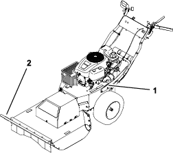
Note: Determine the left and right sides of the machine from the normal operating position.
Recommended Maintenance Schedule(s)
| Maintenance Service Interval | Maintenance Procedure |
|---|---|
| After the first 5 hours |
|
| Before each use or daily |
|
| Every 25 hours |
|
| Every 50 hours |
|
| Every 100 hours |
|
| Before storage |
|
Maintenance Safety
-
Disconnect the spark-plug wire from the spark plug before performing any maintenance procedure.
-
Wear gloves and eye protection when servicing the machine.
-
The blade is sharp; contacting the blade can result in serious personal injury. Wear gloves when servicing the blade.
-
Never tamper with safety devices. Check their proper operation regularly.
-
Tipping the machine may cause the fuel to leak. Fuel is flammable and explosive, and can cause personal injury. Run the engine dry or remove the fuel with a hand pump; never siphon the fuel.
Engine Maintenance
Engine Safety
Shut off the engine before checking the oil or adding oil to the crankcase.
Servicing the Air Cleaner
| Maintenance Service Interval | Maintenance Procedure |
|---|---|
| Before each use or daily |
|
| Every 50 hours |
|
Note: Service the air cleaner more frequently if the operating conditions are extremely dusty or sandy.
Removing the Foam and Paper Elements
-
Park the machine on a level surface, shut off the engine, wait for all moving parts to stop, and remove the key from the ignition switch before leaving the operating position.
-
Clean around the air cleaner to prevent dirt from getting into the engine and causing damage.
-
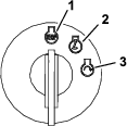
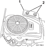
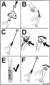
Remove the air-cleaner cover by unscrewing the 2 knobs (Figure 18).
-
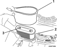
Remove the 2 nuts securing the filter assembly to the housing (Figure 19).
-
Carefully remove the foam and paper-filter elements from the air-cleaner housing.
-
Separate the foam and paper elements.
Cleaning the Foam and Paper Elements
Foam Element:
-
Wash the foam element in liquid soap and warm water.
-
When the element is clean, rinse it thoroughly.
-
Dry the element by squeezing it in a clean cloth.
Note: Do not oil the element.
Important: Replace the foam element if it is torn or worn.
-
Install the foam element onto a clean paper element.
Paper Element:
-
Tap the paper element on a solid, flat surface, and blow it out from the inside with compressed air to remove dust and dirt.
-
Inspect the element for tears, an oily film, and damage to the rubber seal.
Important: Do not clean the paper element with liquids, such as solvents, gasoline, or kerosene. Replace the paper element if it is damaged or cannot be cleaned thoroughly.
-
Clean the inside of the air-cleaner cover of all dirt, dust, and debris.
Installing the Foam and Paper Elements
Important: To prevent engine damage, always operate the engine with the complete foam and paper-air cleaner assembly installed.
Servicing the Engine Oil
Oil Type: Detergent oil (API service SF, SG, SH, SJ, or higher)
Crankcase Capacity: 1.4 L (48 oz) when you change the filter.
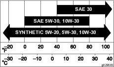
Viscosity: See the table below.
Checking the Engine-Oil Level
| Maintenance Service Interval | Maintenance Procedure |
|---|---|
| Before each use or daily |
|
Note: Check the oil when the engine is cold.
Warning
Contact with hot surfaces may cause personal injury.
Keep hands, feet, face, clothing and other body parts away the muffler and other hot surfaces.
Important: Do not overfill the crankcase with oil and run the engine; engine damage may result.
-
Park the machine on a level surface, shut off the engine, wait for all moving parts to stop, and remove the key from the ignition switch before leaving the operating position.
-
Check the engine-oil level (Figure 21).
Changing the Engine Oil and Filter
| Maintenance Service Interval | Maintenance Procedure |
|---|---|
| After the first 5 hours |
|
| Every 100 hours |
|
Note: Change the engine-oil filter more frequently when the operating conditions are extremely dusty or sandy.
-
Park the machine on a level surface, shut off the engine, wait for all moving parts to stop, and remove the key from the ignition switch before leaving the operating position.
-
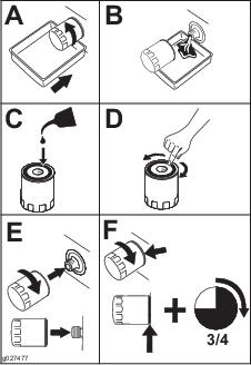
Drain the oil from the engine (Figure 22).
-
Remove the engine-oil filter (Figure 23). After the oil is drained, install a new oil filter.
Note: Ensure the new oil-filter gasket touches the engine, and then an extra 3/4 turn is completed.
-
Slowly pour approximately 80% of the specified amount of oil into the fill hole (Figure 24).
-
Allow 3 to 5 minutes for the oil to settle, then check the oil level (Figure 24).
-
Add oil to the machine so that the oil level reaches the “Full” mark on the dipstick.
Servicing the Spark Plug
| Maintenance Service Interval | Maintenance Procedure |
|---|---|
| Every 50 hours |
|
| Every 100 hours |
|
Ensure that the air gap between the center and side electrodes is correct before installing the spark plug. Use a spark plug wrench for removing and installing the spark plug and a gapping tool or feeler gauge to check and adjust the air gap. Install a new spark plug if necessary.
Type: Champion® RC12YC, Autolite® 3924, or NGK® BPR6ES
Air Gap: 0.76 mm (0.030 inch)
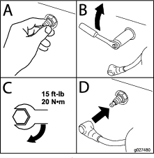
Removing the Spark Plug
-
Park the machine on a level surface, shut off the engine, and remove the key from the ignition switch.
-
Before removing the spark plug(s), clean the area around the base of the plug to keep dirt and debris out of the engine.
-
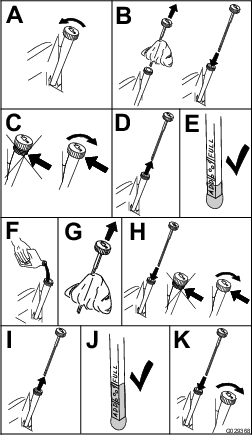
Remove the spark plug (Figure 25).
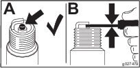
Checking the Spark Plug
Important: Do not clean the spark plug(s). Always replace the spark plug(s) when it has: a black coating, worn electrodes, an oily film, or cracks.
Note: If you see light brown or gray on the insulator, the engine is operating properly. A black coating on the insulator usually means the air cleaner is dirty.
Set the gap to 0.76 mm (0.030 inch).
Installing the Spark Plug
Tighten the spark plug to 20 N∙m (15 ft-lb).
Fuel System Maintenance
Danger
In certain conditions, gasoline is extremely flammable and highly explosive. A fire or explosion from gasoline can burn you, others, and can damage property.
-
Perform any fuel-related maintenance when the engine is cold. Do this outdoors in an open area. Wipe up any gasoline that spills.
-
Never smoke when draining gasoline, and stay away from an open flame or where a spark may ignite the gasoline fumes.
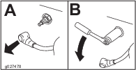
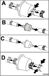
Replacing the In-Line Fuel Filter
| Maintenance Service Interval | Maintenance Procedure |
|---|---|
| Every 100 hours |
|
Never install a dirty filter if it is removed from the fuel line.
-
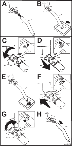
Park the machine on a level surface, shut off the engine, and remove the key from the ignition switch.
-
Close the fuel-shutoff valve.
-
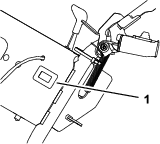
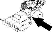
Replace the in-line filter (Figure 28).
Electrical System Maintenance
Electrical System Safety
-
Disconnect the battery before repairing the machine. Disconnect the negative terminal first and the positive last. Connect the positive terminal first and the negative last.
-
Charge the battery in an open, well-ventilated area, away from sparks and flames. Unplug the charger before connecting or disconnecting the battery. Wear protective clothing and use insulated tools.
Warning
Battery posts, terminals, and related accessories contain lead and lead compounds, chemicals known to the State of California to cause cancer and reproductive harm. Wash hands after handling.
Removing the Battery
Warning
Battery terminals or metal tools could short against metal machine components, causing sparks. Sparks can cause the battery gasses to explode, resulting in personal injury.
-
When removing or installing the battery, do not allow the battery terminals to touch any metal parts of the machine.
-
Do not allow metal tools to short between the battery terminals and metal parts of the machine.
Warning
Incorrect battery-cable routing could damage the machine and cables causing sparks. Sparks can cause the battery gasses to explode, resulting in personal injury.
-
Always disconnect the negative (black) battery cable before disconnecting the positive (red) cable.
-
Always connect the positive (red) battery cable before connecting the negative (black) cable.
-
Park the machine on a level surface, shut off the engine, and remove the key from the ignition switch.
-
Disconnect the negative (black) battery cable from the battery.
-
Disconnect the positive (red) battery cable from the battery.
-
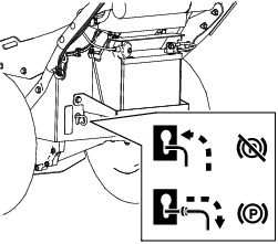
Remove the nuts and securing rods from both sides of the battery, battery cover, and battery tray.
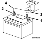
Charging the Battery
| Maintenance Service Interval | Maintenance Procedure |
|---|---|
| Before storage |
|
-
Remove the battery from the chassis; refer to Removing the Battery.
-
Charge the battery for a minimum of 1 hour at 6 to 10 amps.
Note: Do not overcharge the battery.
-
When the battery is fully charged, unplug the charger from the electrical outlet, then disconnect the charger leads from the battery posts (Figure 30).
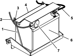
Installing the Battery
-
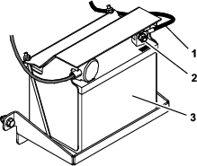
Place the battery on the tray and secure it using the battery cover, 2 securing rods, and 2 nuts (Figure 29).
-
Install the positive battery cable to the positive (+) battery post.
-
Install the negative battery cable to the negative (-) battery post.
-
Slide the red terminal boot onto the positive battery post (Figure 29).
Servicing a Replacement Battery
The original battery is maintenance-free and does not require service. For servicing a replacement battery, refer to the battery manufacturer’s instructions.
Drive System Maintenance
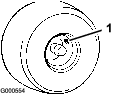
Checking the Tire Pressure
| Maintenance Service Interval | Maintenance Procedure |
|---|---|
| Before each use or daily |
|
| Every 25 hours |
|
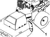
Maintain the air pressure in the tires as specified. Check the pressure at the valve stem (Figure 31). Check the tires when they are cold to get the most accurate pressure reading.
Inflate the tires to 97 kPa (14 psi).
Cooling System Maintenance
Cleaning the Engine Screen
| Maintenance Service Interval | Maintenance Procedure |
|---|---|
| Before each use or daily |
|
To ensure proper cooling, ensure that the air-intake screen, cooling fins, and other external surfaces of the engine are kept clean at all times.
Use a dry brush to clean accumulated debris from the air-intake screen and around the engine.
Important: To prevent contaminating the fuel system, do not use water to clean the engine.
Cleaning the Engine-Cooling Fins and Shrouds
| Maintenance Service Interval | Maintenance Procedure |
|---|---|
| Every 100 hours |
|
-
Park the machine on a level surface, shut off the engine, and remove the key from the ignition switch.
-
Remove the air-intake screen and cooling shrouds.
-
Clean the debris and grass from the engine parts.
-
Install the air-intake screen and cooling shrouds.
Belt Maintenance
Inspecting the Belts
| Maintenance Service Interval | Maintenance Procedure |
|---|---|
| Every 25 hours |
|
Check the belts for cracks, frayed edges, burn marks, or any other damage. Replace damaged belts.
Replacing the Transmission Belt
-
Park the machine on a level surface, disengage the blade, and engage the parking brake.
-
Turn the ignition key to the OFF position, remove the key, and disconnect the spark plug wire from the spark plug.
-
Raise the machine using a hoist or jackstands.
-
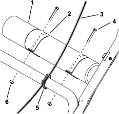
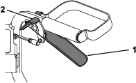
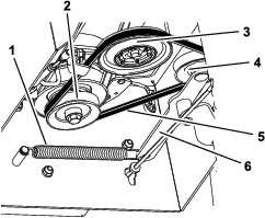
Remove the extension spring from the tension arm (Figure 32).
-
Remove the transmission belt from the pulleys.
-
Wrap the new transmission belt around the clutch, transmission, and tension pulleys (Figure 32).
-
Install the extension spring onto the tension arm.
Replacing the Mower Belt
-
Park the machine on a level surface, disengage the blade, and engage the parking brake.
-
Turn the ignition key to the OFF position, remove the key, and disconnect the spark plug wire from the spark plug.
-
Raise the machine using a hoist or jackstands.
-
Remove the transmission belt; refer to Replacing the Transmission Belt.
-
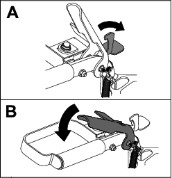
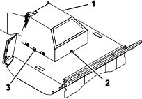
Loosen the left and right side bolts a few turns, and loosen the front bolt until the cover is loose (Figure 33).
Note: Do not remove the bolts.
-
Lift the cover upward to remove it.
-
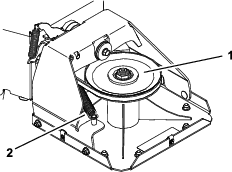
Detach the extension spring (Figure 34).
Caution
The spring is under tension when installed and can cause personal injury.
Wear safety glasses and be careful when removing the spring.
-
Remove the mower belt from the clutch pulley.
-
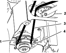
Route the new belt around the clutch pulley, through the belt guide, along the idler pulley, and around the deck pulley (Figure 34 and Figure 35).
Note: Ensure that the belt is seated correctly on both pulleys, with no twists. The belt needs to be in this position until you install the extension spring.
-
Install the extension spring (Figure 34).
-
Lower the belt cover onto the deck, aligning the slots in the cover with the side bolts. Tighten the front bolt, then tighten both side bolts (Figure 33).
-
Install the transmission belt; refer to Replacing the Transmission Belt.
Mower Maintenance
To ensure a superior quality of cut, keep the blade sharp. For convenient sharpening and replacement, you may want to keep extra blades on hand.
Blade Safety
A worn or damaged blade can break, and a piece of the blade could be thrown at you or bystanders, resulting in serious personal injury or death. Trying to repair a damaged blade may result in discontinued safety certification of the product.
-
Inspect the blade periodically for wear or damage.
-
Use care when checking the blade. Wrap the blade or wear gloves, and use caution when servicing the blade. Only replace or sharpen the blade; never straighten or weld them.
Before Inspecting or Servicing the Blade
-
Park the machine on a level surface, disengage the blade, and engage the parking brake.
-
Turn the ignition key to the OFF position, remove the key, and disconnect the spark plug wires from the spark plugs.
-
Tilt the machine so that the deck is off the ground and place wood blocks under the deck to hold it up.
Inspecting the Blade
| Maintenance Service Interval | Maintenance Procedure |
|---|---|
| Before each use or daily |
|
-
Inspect the cutting edges (Figure 36).
-
If the edges are not sharp or have nicks, remove and sharpen the blade; refer to Sharpening the Blade.
-
Inspect the blade.
-
If you notice any crack or wear, immediately install a new blade (Figure 36).

Checking for a Bent Blade
Warning
A blade that is bent or damaged could break apart and could seriously injure or kill you or bystanders.
-
Always replace a bent or damaged blade with a new blade.
-
Do not file or create sharp notches in the edges or surfaces of the blade.
-
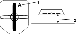
Rotate the blade until the ends face forward and backward.
-
Measure from a level surface to the cutting edge, position A, of the blade (Figure 37).
-
Rotate the opposite ends of the blade forward.
-
Measure from a level surface to the cutting edge of the blade at the same position as in step 2 above.
Note: The difference between the dimensions obtained in steps 2 and 4 must not exceed 3 mm (1/8 inch).
Note: If this dimension exceeds 3 mm (1/8 inch), the blade is bent and must be replaced.
Removing the Blade
Replace the blade if it hits a solid object, if the blade is out of balance, or if a blade is bent. To ensure optimum performance and continued safety conformance of the machine, use genuine Toro replacement blades. Replacement blades made by other manufacturers may result in nonconformance with safety standards.
Note: Flail blades are sharpened on 2 sides, so you can turn over a blade when you remove it for a new sharp edge
Flail Blade Only
-
Hold the blade end using a rag or a thickly padded glove.
-
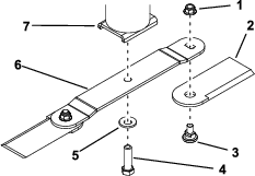
Remove the blade bolt, the curved washer, and blade from the blade mount on the bottom of the spindle-cup assembly (Figure 38).
-
To remove only the flail blades, remove the flails from the blade by removing the flail bolt and nut from each flail.
Straight Blade Only
-
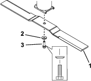
Hold the blade end using a rag or thickly-padded glove.
-
Remove the blade bolt, curved washer, and blade from the spindle cup assembly (Figure 39).
Sharpening the Blade
-
Use a file to sharpen the cutting edge at both ends of the blade (Figure 40).
Note: Maintain the original angle.
Note: The blade retains balance if the same amount of material is removed from both cutting edges.

-
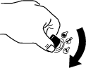
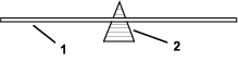
For straight blades only, check the balance of the blade by putting it on a blade balancer (Figure 41).
If the blade is not balanced, file some metal off the back side of the blade (opposite of the cutting edge) only (Figure 38).
Repeat this procedure until the blade is balanced.
Note: If the blade stays in a horizontal position, the blade is balanced.
Installing the Blade
Flail Blade Only
-
Attach the blade to the spindle cup assembly using the blade bolt and curved washer (Figure 38).
Note: Ensure that cupped side of the washer faces the blade, and the convex side of the blade faces the spindle cup.
-
Torque the bolt to 136 to 149 N∙m (100 to 110 ft-lb).
-
To install only the flail blades, secure the flails to the end of the blade using the flail bolt and a new nut for each flail (Figure 38). Torque the nut to 103 to 127 N∙m (76 to 94 ft-lb).
Note: Always replace a removed flail nut with a new nut.
Note: Secure the flails to the bottom of the blade, not the top.
Cleaning
Removing Debris from the Machine
| Maintenance Service Interval | Maintenance Procedure |
|---|---|
| Before each use or daily |
|
Regular cleaning and washing increases the lifespan of the machine. Clean the machine directly after use.
Check before cleaning that the fuel tank cap is properly in place to avoid getting water in the tank.
Use care when using a high-pressure sprayer, because it can damage warning decals, instruction signs, and the engine.