CALIFORNIA
Proposition 65 Warning
This product contains a chemical or chemicals known to the State of California to cause cancer, birth defects, or reproductive harm.
Use of this product may cause exposure to chemicals known to the State of California to cause cancer, birth defects, or other reproductive harm.
Important: Use air-induction, flat-fan nozzles with the covered boom kit to avoid chemical buildup on the covers during application. Refer to the Toro nozzle chart for details.
Note: Install the Spring Upgrade Kit (Part No. 120-8508) with the covered boom.
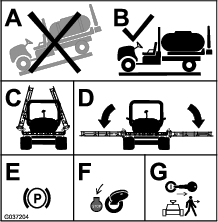
If you leave the key in the key switch, someone could accidently start the engine and seriously injure you or other bystanders.
Remove the key from the key switch before you install the kit.
Chemical substances used in the spreader-sprayer system may be hazardous and toxic to you, bystanders, animals, plants, soils or other property.
Carefully read and follow the chemical warning labels and material safety data sheets (MSDS) for all chemicals used and protect yourself according to the chemical manufacturer's recommendations. Ensure that as little skin as possible is exposed while using chemicals. Use appropriate personal protective equipment (PPE) to guard against personal contact with chemicals, such as:
safety glasses, goggles, and/or face shield
respirator or filter mask
chemical resistant gloves
rubber boots or other substantial footwear
hearing protection
clean change of clothes, soap, and disposable towels, to be kept on-hand, in the event of a chemical spill.
Before working on a sprayer system, make sure that the system has been triple rinsed and neutralized according to the recommendations of the chemical manufacturer(s) and all of the valves have been cycled 3 times.
Move the machine to a level surface.
Lower the outer-boom sections.
Engage the parking brake.
Shut off the engine.
Remove the key from the key switch.
Parts needed for this procedure:
| 11-nozzle, center-boom cover | 1 |
| Rubber cover | 1 |
| Reinforcement plate | 1 |
| Pop rivet (3/16 x 1/2 inch) | 11 |
| Washer (3/16 inch) | 11 |
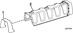
Note: One side of the center-boom cover is already attached, so you only need to install on 1 side of the cover.
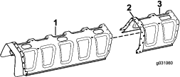
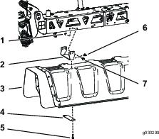
Align the holes on the rubber cover with the holes on the center-boom cover (Figure 2).
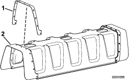
Align the holes on the reinforcement plate with the holes on the rubber cover (Figure 3).
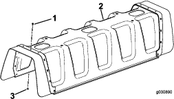
Install 11 pop rivets (3/16 x 1/2 inch) and washers (3/16 inch) to the center-boom cover (Figure 4).
Parts needed for this procedure:
| 12-nozzle, center-boom cover | 1 |
| Pop rivet (3/16 x 1/2 inch) | 22 |
| Washer (3/16 inch) | 22 |
| Rubber cover | 1 |
| Reinforcement plate | 1 |
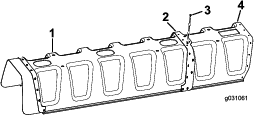
Align the holes on the 11-nozzle boom cover with the holes on the reinforcement plate attached to the 12-nozzle boom cover (Figure 5).
Note: The reinforcement plate comes attached to the 12-nozzle boom with pop rivets.
Install 11 pop rivets (3/16 x 1/2 inch) and washers (3/16 inch) to the reinforcement plate, attaching 11-nozzle cover to the 12-nozzle cover (Figure 6).
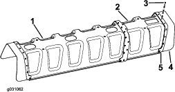
Using 11 pop rivets (3/16 x 1/2 inch) and washers (3/16 inch), install the rubber cover and reinforcement plate (from the 11-nozzle cover) to the 12-nozzle cover (Figure 7).
Parts needed for this procedure:
| Center-boom bracket (2014 and earlier models) | 2 |
| Boom-mount plate | 2 |
| U-nut | 8 |
| Hex-head bolt (3/8 x 1-1/4 inch) | 8 |
| Model/serial number decal | 1 |
| Regulatory decal (119-4986) | 1 |
| Flange nut (3/8 inch) | 8 |
| Washer plate | 4 |
| Hex-head bolt (5/16 x 1-1/4 inch) | 8 |
| Center-boom bracket (2015 and later models) | 4 |
Attach the model/serial number decal and the regulatory decal to 1 of the center boom brackets as shown in Figure 8.
Note: Before applying the decals, clean the decal area and ensure that it is free of dirt, grease, or other foreign material.
For 2014 and earlier models:
Install each of the 2 center brackets and boom-mount plates to the center boom using 2 hex-head bolts (3/8 x 1-1/4 inch) and 2 flange nuts (3/8 inch) as shown in Figure 8.
Note: When mounting the kit to a sprayer, use the holes in the center bracket to attach the kit to the unit. When mounting the kit to a vehicle, use the holes in the boom-mount plate to attach the kit to the unit.
Install the center cover to the center-boom brackets using 4 U-nuts, 2 washer plates, and 4 hex-head bolts (5/16 x 1-1/4 inch) as shown in Figure 8.
For 2015 and later models:
Important: If you are installing an 11-nozzle assembly, you will only use 4 U-nuts, 4 hex-head bolts (3/8 x 1-1/4 inch), 4 flange nuts (3/8 inch), 2 washer plates, and 2 center-boom brackets.
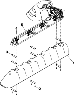
Install the center cover to the bracket, using 8 U-nuts, 4 washer plates, and 8 hex-head bolts (5/16 x 1-1/4 inch) as shown in Figure 9.
Install each of the 4 center-boom brackets and boom mount plates to the center boom using 4 hex-head bolts (3/8 x 1-1/4 inch) and 4 flange nuts (3/8 inch) as shown in Figure 9.
Parts needed for this procedure:
| Wing-boom cover | 2 |
| Washer plate | 16 |
| U-nut | 12 |
| Hex-head bolt (5/16 x 1-1/4 inch) | 12 |
Orient the spray nozzles on both wing booms straight downward, so it can fit in the holes of the wing-boom covers.
Install 1 of the wing-boom covers (Figure 10) using 8 washer plates, 6 hex-head bolts (5/16 x 1-1/4 inch), and 6 U-nuts.
Repeat step 2 to install the other wing-boom cover.
Parts needed for this procedure:
| Drain-valve-mount bracket | 1 |
| Carriage screw (5/16 x 1-1/4 inch) | 2 |
| Flange nut (5/16 inch) | 3 |
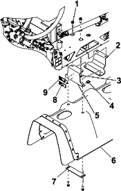
Remove the 2 carriage bolts (5/16 x 1 inch) and 2 flange locknuts (5/16 inch) that secure the fender and mud flap to the fender strap (Figure 11).
Note: Discard the carriage bolt and locknut.

Align the holes in the drain-valve bracket, fender strap, mud flap, and fender (Figure 11).

Assemble the valve bracket, fender strap, mud flap, and fender (Figure 12) with the 2 carriage bolts (5/16 x 1-1/4 inches) and 2 flange locknuts (5/16 inch).
Torque the carriage bolts and flange locknuts to 20 to 25 N∙m (175 to 225 in-lb).
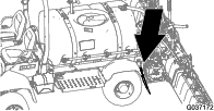
Remove the lynch pin that secures the drain valve to the tank bracket (Figure 13).
Note: The drain valve is located on the support bracket for the hydraulic tank.
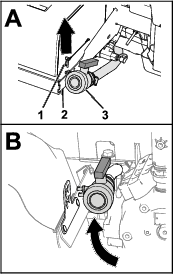
Move the drain valve between the left, rear fender and the sprayer pump (Figure 13).
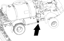
Remove the lynch pin that secures the drain valve to the sprayer-pump bracket (Figure 14).


Move the drain valve between the left, rear fender and the sprayer pump (Figure 14).
Parts needed for this procedure:
| Flange nut (5/16 inch) | 2 |
| Flange-head bolts (5/16 x 1 inch) | 2 |
Remove the 2 mounting pegs from the drain valve (A of Figure 15).
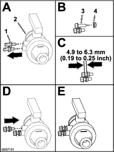
Thread the 2 flange locknuts (5/16 inch) onto the 2 flange-head bolts (5/16 x 1 inch) as shown in (B and C of Figure 15).
Assemble the flange locknuts and flange-head bolts to the drain valve and tighten them with a wrench (D and E of Figure 15).
Note: Ensure that the locknuts are secured tight to the drain valve.
Align the locknuts of the drain valve with the holes of the keyhole slots in the drain-valve bracket (A of Figure 16).
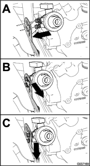
Move the drain valve outboard and down to secure the valve to the bracket (B and C of Figure 16).
Verify that the outer-boom covers do not bind against the center-boom cover when you raise and lower the booms.
Note: Install additional washer plates between the outer-boom covers and the truss frame of the outer-boom section to add clearance between the covers as needed. Refer to Figure 10.
Close section