| Maintenance Service Interval | Maintenance Procedure |
|---|---|
| Before each use or daily |
|
Introduction
This machine is a ride-on, multi-purpose machine intended to be used by professional, hired operators in commercial applications. It is primarily designed for maintaining grass on well-maintained lawns in parks, sports fields, and on commercial grounds. It is not designed for cutting brush, mowing grass and other growth alongside highways, or for agricultural uses.
Read this information carefully to learn how to operate and maintain your product properly and to avoid injury and product damage. You are responsible for operating the product properly and safely.
You may contact Toro directly at www.Toro.com for product safety and operation training materials, accessory information, help finding a dealer, or to register your product.
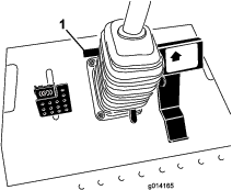
Whenever you need service, genuine Toro parts, or additional information, contact an Authorized Service Dealer or Toro Customer Service and have the model and serial numbers of your product ready. Figure 1 identifies the location of the model and serial numbers on the product. Write the numbers in the space provided.
This manual identifies potential hazards and has safety messages identified by the safety-alert symbol (Figure 2), which signals a hazard that may cause serious injury or death if you do not follow the recommended precautions.

This manual uses 2 words to highlight information. Important calls attention to special mechanical information and Note emphasizes general information worthy of special attention.
This product complies with all relevant European directives; for details, please see the separate product specific Declaration of Conformity (DOC) sheet.
Warning
CALIFORNIA
Proposition 65 Warning
Diesel engine exhaust and some of its constituents are known to the State of California to cause cancer, birth defects, and other reproductive harm.
It is a violation of California Public Resource Code Section 4442 or 4443 to use or operate the engine on any forest-covered, brush-covered, or grass-covered land unless the engine is equipped with a spark arrester, as defined in Section 4442, maintained in effective working order or the engine is constructed, equipped, and maintained for the prevention of fire.
Safety
This machine has been designed in accordance with EN ISO 5395:2013 and ANSI B71.4-2012.
General Safety
This product is capable of amputating hands and feet and of throwing objects. Always follow all safety instructions to avoid serious personal injury.
Using this product for purposes other than its intended use could prove dangerous to you and bystanders.
-
Read and understand the contents of this Operator’s Manual before starting the engine.
-
Do not put your hands or feet near moving components of the machine.
-
Do not operate the machine without all guards and other safety protective devices in place and working on the machine.
-
Keep clear of any discharge opening. Keep bystanders and pets a safe distance away from the machine.
-
Keep children out of the operating area. Never allow children to operate the machine.
-
Stop the machine and shut off the engine before servicing, fueling, or unclogging the machine.
Improperly using or maintaining this machine can result in injury. To reduce the potential for injury, comply with these safety instructions and always pay attention to the safety-alert symbol, which means Caution, Warning, or Danger—personal safety instruction. Failure to comply with these instructions may result in personal injury or death.
You can find additional safety information where needed throughout this Operator’s Manual.
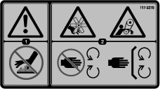
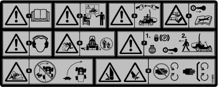
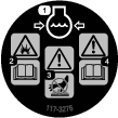
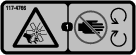
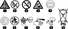
Safety and Instructional Decals
 |
Safety decals and instructions are easily visible to the operator and are located near any area of potential danger. Replace any decal that is damaged or missing. |


Setup
Installing the PTO Driveshaft to an Optional Mower Deck or QAS
Parts needed for this procedure:
| PTO driveshaft | 1 |
| Bolt (5/16 x 1-3/4 inches) | 4 |
| Locknut (5/16 inch) | 4 |
| Roll pin (3/16 x 1-1/2 inches) | 2 |
Note: Installing the PTO driveshaft is easier if you position the machine on a hoist.
-
Park the machine on a level surface, engage the parking brake, shut off the engine, and remove the key from the key switch.
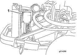
Warning
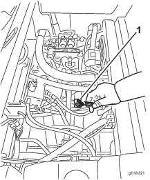
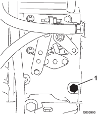
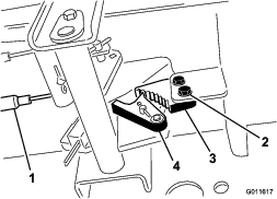
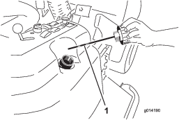
Do not start the engine and engage the PTO switch when the PTO driveshaft is disconnected from the cutting deck. If you start the engine and the PTO shaft is allowed to rotate, serious personal injury and machine damage could result. Before the PTO driveshaft is disconnected from the cutting deck, disconnect the PTO solenoid-valve-coil connector from the wire harness to prevent unintentionally engaging the PTO clutch.
-
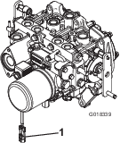
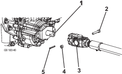
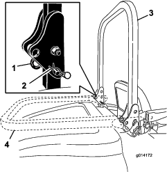
Disconnect the wire-harness connector from the PTO solenoid-valve-coil connector (Figure 3).
-
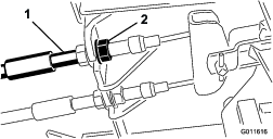
Position the PTO driveshaft under the front of the machine. Ensure that the slip-shaft yoke of the driveshaft is positioned toward the transmission driveshaft (Figure 4).
-
Align the spline and roll-pin hole of the driveshaft yoke with the transmission driveshaft.
-
Slide the PTO driveshaft end yoke onto the transmission driveshaft.
-
Secure the end yoke of the PTO driveshaft as follows:
-
Install the roll pin in the end yoke and shaft.
-
Install the bolts through the driveshaft end yoke.
-
Install and tighten the locknuts to secure the end yoke to the PTO driveshaft.
Note: Retain the remaining bolts, locknuts, and roll pin to secure the other end of the driveshaft to the attachment gearbox shaft.
-
Torque the locknuts to 20 to 25 N-m (175 to 225 in-lb).
-
-
Lubricate the grease fittings on the PTO driveshaft.
-
After you connect the other end of the driveshaft to the attachment gearbox shaft, connect the wire-harness connector to the PTO solenoid-valve-coil connector (Figure 3).
Using the Optional Mower-Deck-Mounting Hardware
Parts needed for this procedure:
| Retainer pin | 2 |
| Grease fitting | 2 |
| Washer head screw (5/16 x 7/8 inch) | 2 |
Note: These components and procedure are required only if a mower deck that requires retainer pins is mounted to the traction unit. Refer to the mower deck Operator’s Manual for the installation instructions.
Note: If you are not installing a mower deck on the traction unit, remove or tie up the 4 deck-lift chains from the lift suspension.
Checking the Tire Pressure
The tires are overinflated for shipping. Therefore, release some of the air to reduce the pressure; refer to Checking the Tire Pressure.
Checking the Fluid Levels
-
Check the hydraulic-fluid level before starting the engine, refer to Checking the Hydraulic System.
-
Check the engine-oil level before starting the engine, refer to Checking the Engine-Oil Level.
-
Check the cooling system before starting the engine; refer to Checking the Cooling System .
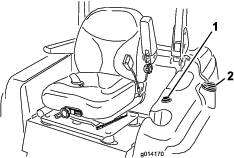
Adjusting the Roll Bar
Models with Roll Bar Only
Important: Always use the seat belt when the roll bar is in the raised and locked position. Do not use the seat belt when the roll bar is in the lowered position.
-
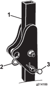
Remove the hairpin cotters and the pins from the roll bar (Figure 5).
-
Raise the roll bar to the upright position and install the 2 pins and secure them with the hairpin cotters (Figure 5).
Note: If you must lower the roll bar, push the bar forward to relieve pressure on the pins, remove the pins, lower the bar slowly, and secure it with the pins so that it does not damage the hood.
Product Overview
Become familiar with all the controls before you start the engine and operate the machine.
Traction Pedal
The traction pedal (Figure 6) controls the forward and reverse operation. Press the top of the pedal to move forward and the bottom to move rearward. The ground speed depends on how far you press the pedal. For no load, maximum ground speed, fully press the pedal while the throttle is in the FAST position.
To stop the machine, reduce the foot pressure on the traction pedal and allow it to return to the center position.
Brake Pedal
Use the brake pedal with the brake-pedal latch to engage and disengage the parking brake (Figure 6). To stop the machine, release the traction pedal and allow it to return to the center position. You can use the brake to assist in stopping the machine in an emergency situation.
Parking Brake
To engage the parking brake, push down on the brake pedal and press the top forward to latch (Figure 6). To release the parking brake, press the brake pedal until the parking brake latch retracts without contacting the locking mechanism.
Tilt Steering Pedal
To tilt the steering wheel toward you, press the foot pedal down, pull the steering tower toward you to the most comfortable position, and release the pedal (Figure 6). To move the steering wheel away from you, press the foot pedal and release it when the steering wheel reaches the desired operating position.
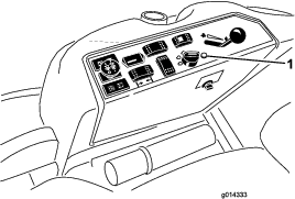
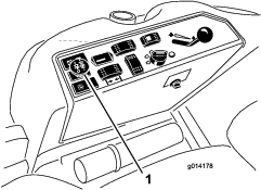
Ignition Switch
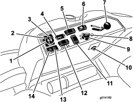
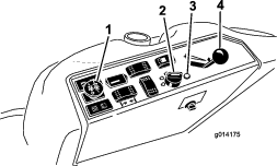
The ignition switch has 3 positions: OFF, ON/PREHEAT, and START (Figure 7).
Diagnostic Light
4-Wheel Drive Machines Only
The diagnostic light illuminates when the system detects a fault (Figure 7).
Throttle Lever
The throttle lever (Figure 7) controls the engine speed. Moving the throttle lever forward toward the FAST position increases the engine speed. Moving it rearward toward the SLOW position decreases the engine speed. The throttle controls the speed of the PTO and, with the traction pedal, controls the ground speed of the machine. Always run the machine with the throttle in the FAST position when operating attachments.
Power-Takeoff (PTO) Switch
The power-takeoff (PTO) switch starts and stops the attachment (Figure 7).
Steering Selector Switch
4-Wheel Drive Machines Only
Press the steering selector switch to the rear to engage 4-wheel steering and forward to return to 2-wheel steering (Figure 7).
Hour Meter
The hour meter (Figure 7) records the number of hours that the engine has operated. It operates when the key switch is in the RUN position. Use these times for scheduling regular maintenance.
Glow-Plug-Indicator Light (Orange Light)
The glow-plug-indicator light (Figure 7) turns on when you turn the ignition switch to the ON position. It remains on for 6 seconds. When the light turns off, you can start the engine.
Engine-Coolant-Temperature-Warning Light
This light glows and the attachment stops if the temperature of the engine coolant is high (Figure 7). If you do not stop the machine and the coolant temperature rises another 7°C (20° F), the engine shuts off.
Important: If the attachment shuts down and the temperature warning light is on, push the PTO knob down, drive the machine to a safe, flat area, move the throttle lever to the SLOW position, allow the traction pedal to move to the NEUTRAL position, and engage the parking brake. Allow the engine to idle for several minutes while it cools to a safe level. Shut off the engine and check the cooling system; refer to Checking the Cooling System .
Charge Indicator
The charge indicator illuminates when the charging-system circuit malfunctions (Figure 7).
Oil-Pressure-Warning Light
The oil-pressure-warning light (Figure 7) glows when the oil pressure in engine drops below a safe level. If low oil pressure ever occurs, shut off the engine and determine the cause. Repair the damage before starting the engine again.
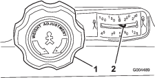
Fuel Gauge
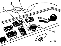
The fuel gauge (Figure 8) indicates the amount of fuel remaining in the fuel tank.
Cab Controls
Model with Cab Only
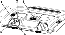
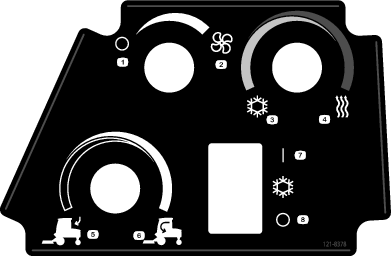
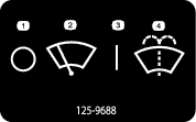
Air-Recirculation Control
Sets the cab to either recirculate the air in the cabin or to draw air into the cabin from outside (Figure 9).
-
Set it to recirculate the air when using the air-conditioning.
-
Set it to draw air in when using the heater or fan.
Fan-Control Knob
Rotate the fan-control knob to regulate the speed of the fan (Figure 9).
Temperature-Control-Knob
Rotate the temperature-control knob to regulate the air temperature in the cab (Figure 9).
Windshield-Wiper Switch
Use this switch to turn the wind shield wipers on or off (Figure 9).
Air-Conditioning Switch
Use this switch to turn the air conditioning on or off (Figure 9).
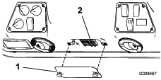
Windshield Latch
Lift up the latch to open the windshield (Figure 10). Press in the latch to lock the windshield in the open position. Pull out and down on the latch to close and secure the windshield.
Rear Window Latch
Lift up the latch to open the rear window. Press in the latch to lock the window in the open position. Pull out and down on the latch to close and secure the window (Figure 10).
Important: You must close the rear window before opening the hood; otherwise, damage may occur.
Note: Specifications and design are subject to change without notice.
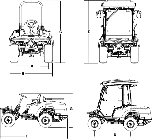
| Description | Figure 11 reference | Dimension or Weight | |
| Height with roll bar up | C | 201 cm (79 inches) | |
| Height with roll bar down | G | 137 cm (54 inches) | |
| Height with cab | D | 225 cm (88-1/2 inches) | |
| Overall length | F | 276 cm (108-1/2 inches) | |
| Overall width | B | 147 cm (58 inches) | |
| Wheel base | E | 155 cm (61 inches) | |
| Wheel tread (tire center to center) rear | A | 112 cm (44 inches) | |
| Ground clearance | 15 cm (6 inches) | ||
| 4-Wheel Drive Machine with ROPS | Machine with Cab | 2-Wheel Drive Machine with ROPS | |
| No mower deck | 1,134 kg (2,500 lb) | 1,361 kg (3,000 lb) | 1,088 kg (2,398 lb) |
| 72 inch side discharge mower deck | 1,344 kg (2,964 lb) | 1,571 kg (3,464 lb) | 1,298 kg (2,862 lb) |
| 72 inch base mower deck | 1,323 kg (2,916 lb) | 1,549 kg (3,416 lb) | 1,276 kg (2,814 lb) |
| 62 inch base mower deck | 1,305 kg (2,878 lb) | 1,532 kg (3,378 lb) | 1,259 kg (2,776 lb) |
| 100 inch rear discharge mower deck | 1,492 kg (3,290 lb) | 1,719 kg (3,790 lb) | 1,446 kg (3,188 lb) |
Attachments/Accessories
A selection of Toro approved attachments and accessories is available for use with the machine to enhance and expand its capabilities. Contact your Authorized Service Dealer or Distributor or go to www.Toro.com for a list of all approved attachments and accessories.
Operation
Note: Determine the left and right sides of the machine from the normal operating position.
Before Operation
Before Operation Safety
General Safety
-
Never allow children or untrained people to operate or service the machine. Local regulations may restrict the age of the operator. The owner is responsible for training all operators and mechanics.
-
Become familiar with the safe operation of the equipment, operator controls, and safety signs.
-
Know how to stop the machine and engine quickly.
-
Check that operator-presence controls, safety switches, and shields are attached and functioning properly. Do not operate the machine unless they are functioning properly.
-
Before mowing, always inspect the machine to ensure that the blades, blade bolts, and cutting assemblies are in good working condition. Replace worn or damaged blades and bolts in sets to preserve balance.
-
Inspect the area where you will use the machine and remove all objects that the machine could throw.
Fuel Safety
-
Use extreme care in handling fuel. It is flammable and its vapors are explosive.
-
Extinguish all cigarettes, cigars, pipes, and other sources of ignition.
-
Use only an approved fuel container.
-
Never remove the fuel cap or fill the fuel tank while the engine is running or hot.
-
Never refuel the machine in an enclosed space.
-
Never store the machine or fuel container where there is an open flame, spark, or pilot light, such as on a water heater or other appliance.
-
If you spill fuel, do not attempt to start the engine; avoid creating any source of ignition until the fuel vapors have dissipated.
Filling the Fuel Tank
Recommended Fuel
Use only clean, fresh diesel fuel or biodiesel fuels with low (<500 ppm) or ultra low (<15 ppm) sulfur content. The minimum cetane rating should be 40. Purchase fuel in quantities that you can use within 180 days to ensure that the fuel is fresh.
Fuel Tank Capacity: 51 L (13.5 US gallons)
Use summer-grade diesel fuel (No. 2-D) at temperatures above -7°C (20°F) and winter grade (No. 1-D or No. 1-D/2-D blend) below that temperature. Using winter-grade fuel at lower temperatures provide a lower flash point and cold-flow characteristics, which eases starting and reduces plugging of the fuel filter.
Using summer-grade fuel above -7°C (20°F) contributes toward longer life of the fuel pump and increased power compared to winter-grade fuel.
Important: Do not use kerosene or gasoline instead of diesel fuel. Failing to observe this caution will damage the engine.
Biodiesel Ready
This machine can also use a biodiesel blended fuel of up to B20 (20% biodiesel, 80% petrodiesel). The petrodiesel portion should be ultra-low sulfur. Observe the following precautions:
-
The biodiesel portion of the fuel must meet specification ASTM D6751 or EN14214.
-
The blended fuel composition should meet ASTM D975 or EN590.
-
Biodiesel blends may damage painted surfaces.
-
Use B5 (biodiesel content of 5%) or lesser blends in cold weather.
-
Check all seals, hoses, and gaskets in contact with fuel as they may degrade over time.
-
Espect the fuel filter to plug up for a time after converting to biodiesel-blended fuel.
-
Contact your distributor for more information on biodiesel fuel.
Adding Fuel
Note: If possible, fill the fuel tank after each use. This minimizes possible buildup of condensation inside the fuel tank.
-
Park the machine on a level surface, engage the parking brake, lower the cutting deck, shut off the engine, and remove the key from the key switch.
-
Clean around the fuel-tank cap and remove the cap (Figure 12).
Important: Do not open the fuel tank when parked on a hill. The fuel could spill out.
-
Add fuel to the fuel tank until the level is even with the bottom of the filler neck. Do not overfill the fuel tank.
-
Install the fuel-tank cap and secure. Wipe up any spilled fuel.
Positioning the Standard Seat
Changing the Seat Position
The seat can move forward and backward. Position the seat where you have the best control of the machine and are most comfortable.
-
To adjust the seat, move the lever sideways to unlock the seat (Figure 13).
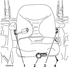
-
Slide the seat to the desired position and release the lever to lock the seat in position.
-
Verify that the seat has locked into place by attempting to move it back and forth.
Changing the Seat Suspension
You can adjust the seat to provide a smooth and comfortable ride. Position the seat where you are most comfortable.
Without sitting on the seat, turn the knob in front in either direction to provide the best comfort (Figure 13).
Changing the Back Position
You can adjust the back of the seat to provide a comfortable ride. Position the back of the seat where it is most comfortable.
To adjust the back of the seat, turn the knob, located under the right-side armrest, in either direction to provide the best comfort (Figure 13).
Changing the Lumbar Support
You can adjust the back of the seat to provide a customized lumbar support for your lower back.
To adjust the back of the seat, turn the knob, under the left-side armrest, in either direction to provide the best comfort (Figure 13).
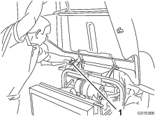
Raising and Lowering the Seat
To access the hydraulic and other systems under the seat, you must unlatch the seat and swing it forward.
-
Move the seat latch, located on the left side of the seat, rearward to unlatch the seat and pull forward on the top of the seat (Figure 15).
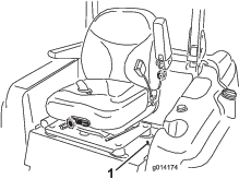
-
To lower the seat, pull up the seat-latch-release bar and lower the seat into the locked position.
During Operation
During Operation Safety
General Safety
-
The owner/operator can prevent and is responsible for accidents that may cause personal injury or property damage.
-
Wear appropriate clothing, including eye protection; slip-resistant, substantial foot protection; and hearing protection. Tie back long hair and do not wear jewelry.
-
Do not operate the machine while ill, tired, or under the influence of alcohol or drugs.
-
Never carry passengers on the machine and keep bystanders and pets away from the machine during operation.
-
Operate the machine only in good visibility to avoid holes or hidden hazards.
-
Avoid mowing on wet grass. Reduced traction could cause the machine to slide.
-
Before you start the engine, ensure that all drives are in neutral, the parking brake is engaged, and you are in the operating position.
-
Keep your hands and feet away from the cutting units. Keep clear of the discharge opening at all times.
-
Look behind and down before backing up to be sure of a clear path.
-
Use care when approaching blind corners, shrubs, trees, or other objects that may obscure your vision.
-
Stop the blades whenever you are not mowing.
-
Stop the machine and inspect the blades after striking an object or if there is an abnormal vibration in the machine. Make all necessary repairs before resuming operation.
-
Slow down and use caution when making turns and crossing roads and sidewalks with the machine. Always yield the right-of-way.
-
Disengage the drive to the cutting unit and shut off the engine before adjusting the height of cut (unless you can adjust it from the operating position).
-
Never run an engine in an area where exhaust gasses are enclosed.
-
Never leave a running machine unattended.
-
Before leaving the operating position (including to empty the catchers or to unclog the chute), do the following:
-
Park the machine on level ground.
-
Disengage the power takeoff and lower the attachments.
-
Engage the parking brake.
-
Shut off the engine and remove the key from the key switch.
-
Wait for all moving parts to stop.
-
-
Do not operate the machine when there is the risk of lightning.
-
Do not use the machine as a towing vehicle.
-
Use accessories, attachments, and replacement parts approved by The Toro® Company only.
Rollover Protection System (ROPS) Safety
-
Do not remove the ROPS from the machine.
-
Ensure that the seat belt is attached and that you can release it quickly in an emergency.
-
Check carefully for overhead obstructions and do not contact them.
-
Keep the ROPS in safe operating condition by thoroughly inspecting it periodically for damage and keeping all the mounting fasteners tight.
-
Replace a damaged ROPS. Do not repair or alter it.
Machines with Cabs
-
The ROPS is an integral and effective safety device.
-
A cab installed by Toro is a roll bar.
-
Always wear your seat belt.
Machines with a Foldable Roll Bar
-
Always use the seat belt with the roll bar in the raised position.
-
The ROPS is an integral safety device. Keep a folding roll bar in the raised and locked position, and use the seat belt when operating the machine with the roll bar in the raised position.
-
Lower a folding roll bar temporarily only when necessary. Do not wear the seat belt when the roll bar is folded down.
-
Be aware that there is no rollover protection when a folded roll bar is in the down position.
-
Check the area that you will be mowing and never fold down a folding roll bar in areas where there are slopes, drop-offs, or water.
Slope Safety
-
Establish your own procedures and rules for operating on slopes. These procedures must include surveying the site to determine which slopes are safe for machine operation. Always use common sense and good judgment when performing this survey.
-
Slopes are a major factor related to loss-of-control and tip-over accidents, which can result in severe injury or death. Operating the machine on any slope requires extra caution.
-
Operate the machine at a lower speed when you are on a slope.
-
If you feel uneasy operating the machine on a slope, do not do it.
-
Watch for holes, ruts, bumps, rocks, or other hidden objects. Uneven terrain could overturn the machine. Tall grass can hide obstacles.
-
Choose a low ground speed so you will not have to stop or shift while on a slope.
-
A rollover can occur before the tires lose traction.
-
Avoid operating the machine on wet grass. Tires may lose traction; regardless if the brakes are available and functioning.
-
Avoid starting, stopping, or turning the machine on a slope.
-
Keep all movement on slopes slow and gradual. Do not suddenly change the speed or direction of the machine.
-
Do no operate the machine near drop-offs, ditches, embankments, or bodies of water. The machine could suddenly roll over if a wheel goes over the edge or the edge caves in. Establish a safety area between the machine and any hazard (2 machine widths).
Think Safety First
Please read all safety instructions and symbols in the safety section. Knowing this information could help you or bystanders avoid injury.
Caution
This machine produces sound levels in excess of 85 dBA at the operator’s ear and can cause hearing loss through extended periods of exposure.
Wear hearing protection when operating this machine.
Using the Rollover-Protection System (ROPS)—2-Wheel Drive with ROPS and 4-Wheel Drive with ROPS Models Only
-
Keep the roll bar in the raised and locked position and use the seat belt when operating the machine.
-
Ensure that you can release the seat belt quickly in an emergency situation.
-
Check the area that you will mow and never fold the roll bar in areas where there are slopes, drop-offs, or water.
Warning
To avoid injury or death from rollover, keep the roll bar in the raised locked position and use the seat belt.
Ensure that the seat plate is secured with the seat latch.
Warning
You have no rollover protection when the roll bar is in the down position.
-
Lower the roll bar only when necessary.
-
Do not wear the seat belt when the roll bar is in the down position.
-
Drive slowly and carefully.
-
Raise the roll bar as soon as clearance permits.
-
Check carefully for overhead clearances (i.e., branches, doorways, electrical wires) before driving under any objects and do not contact them.
-
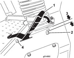
To lower the roll bar, remove the hairpin cotters, push the roll bar forward against the springs, and remove the 2 pins (Figure 18).
-
Lower the roll bar to the down position (Figure 18).
-
Install the 2 pins and secure them with the hairpin cotters (Figure 18).
Important: Ensure that the seat is secured with the seat latch.
-
To raise the roll bar, remove the hairpin cotter pins and remove the 2 pins (Figure 18).
-
Raise the roll bar to the upright position and install the 2 pins and secure them with the hairpin cotters (Figure 18).
Important: Always use the seat belt when the roll bar is in the raised and locked position. Do not use the seat belt when the roll bar is in the lowered position.
Starting and Shutting off the Engine
Starting the Engine
-
Raise the roll bar up and lock it into place, sit on the seat, and fasten the seat belt.
-
Ensure that the traction pedal is in the NEUTRAL position.
-
Engage the parking brake.
-
Move the power-takeoff (PTO) switch to the OFF position (Figure 19).
-
Move the throttle lever midway between the FAST and SLOW positions (Figure 19).
-
Turn the ignition key clockwise to the RUN position (Figure 20).
The glow-plug-indicator light should turn on for 6 seconds.
-
After the glow-plug-indicator light turns off, turn the key to the START position. When the engine starts, release the key.
Important: Use starting cycles of no more than 15 seconds per minute to avoid overheating the starter motor.
Note: You may need to repeat this procedure when starting the engine for the first time after adding fuel to an empty fuel system.
-
Leave the throttle midway between the SLOW and FAST positions until the engine and the hydraulic system warm up.
Important: When you start the engine for the first time, change the engine oil, or overhaul the engine, transmission, or wheel motor, operate the machine with the throttle lever in the SLOW position in both the forward and reverse directions for 1 to 2 minutes. Also, operate the lift lever and PTO lever to ensure that all parts are operating properly. Then shut off the engine and check the fluid levels, check for oil leaks, loose parts, and any other problems.
Shutting off the Engine
-
Disengage the PTO, ensure that the traction pedal is in the NEUTRAL position, engage the parking brake, and move the throttle lever to the SLOW position.
-
Let the engine idle for 60 seconds.
-
Turn the ignition key to the OFF position (Figure 20). Wait for all moving parts to stop before leaving the operating position.
-
Remove the key before transporting or storing the machine.
Important: Make sure to remove the key, as the fuel pump or accessories may run and cause the battery to lose charge.
Driving the Machine
The throttle control regulates the engine speed as measured in rpm (revolutions per minute). Place the throttle control in the FAST position for best performance. Always operate the throttle in the FAST position when mowing.
Stopping the Machine
To stop the machine, release the traction pedal to the NEUTRAL position.
Engage the parking brake whenever you leave the machine. Remove the key from the key switch.
The Safety-Interlock System
Caution
If the safety-interlock switches are disconnected or damaged, the machine could operate unexpectedly, causing personal injury.
-
Do not tamper with the interlock switches.
-
Check the operation of the interlock switches daily and replace any damaged switches before operating the machine.
Understanding the Safety Interlock System
The safety-interlock system is designed to prevent the engine from starting unless the following occurs:
-
You are sitting on the seat or the parking brake is engaged.
-
The power takeoff (PTO) is disengaged.
-
The traction pedal is in the NEUTRAL position
-
The engine temperature is below the maximum operating temperature.
The safety-interlock system is also designed to shut off the engine when you move the traction pedal from the NEUTRAL position with the parking brake engaged. If you rise from the seat when the PTO is engaged there is a 1-second delay and then the engine shuts off.
Testing the Safety-Interlock System
If the safety system does not operate as described below, have an Authorized Service Dealer repair the system immediately.
-
Sit on the seat, engage the parking brake, and move the PTO to the ON position. Try starting the engine: The engine should not start.
-
Sit on the seat, engage the parking brake, move the PTO to the OFF position, and engage the traction pedal. Try starting the engine: The engine should not start.
-
Sit on the seat, engage the parking brake, move the PTO switch to the OFF position, and allow the traction pedal to return to the NEUTRAL position. Start the engine. While the engine is running, release the parking brake, engage the PTO and rise slightly from the seat: The engine should shut off within 2 seconds.
-
With an empty seat, engage the parking brake, move the PTO switch to the OFF position and move the traction pedal to the NEUTRAL position. Start the engine. While the engine is running, engage the traction pedal; the engine should shut off within 2 seconds.
-
With an empty seat, disengage the parking brake, move the PTO switch to the OFF position, and allow the traction pedal to return to the NEUTRAL position. Try starting the engine: The engine should not start.
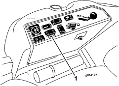
Understanding the Diagnostic Light
The machine comes with a diagnostic light that indicates if the electronic controller senses an electronic malfunction. The diagnostic light is located on the control panel (Figure 21). When the electronic controller is functioning correctly and the key switch is moved to the ON position, the controller diagnostic light will turn on for 3 seconds and turn off to indicate that the light is working properly. If the engine shuts off, the light will turn on steady until you change the key position. The light blinks if the controller detects a malfunction in the electrical system. The light stops blinking and automatically resets when you turn the key switch to the OFF position when the fault has been resolved.
When the controller diagnostic light blinks, 1 of the following problems has been detected by the controller:
-
An output has been shorted.
-
An output has an open circuit.
Use the diagnostic display to determine which output is malfunctioning; refer to Checking the Interlock Switches.
If the diagnostic light does not come on when the key switch is in the ON position, this indicates that the electronic controller is not operating. Possible causes are as follows:
-
The light is burned out.
-
The fuses are blown.
-
The electronic controller is not functioning correctly.
Check the electrical connections, input fuses, and diagnostic light bulb to determine the malfunction. Ensure that the loop-back connector is secured to the wire-harness connector.
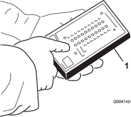
Diagnostic Ace Display
The machine comes with an electronic controller which controls most of the machine functions. The controller determines what function is required for various input switches (e.g., seat switch and key switch) and turns on the outputs to actuate solenoids or relays for the requested machine function.
For the electronic controller to control the machine as desired, each of the input switches, output solenoids, and relays must be connected and functioning properly.
Use the Diagnostic ACE display tool and overlay to help verify and correct electrical functions of the machine. Contact your Toro Distributor for assistance.
Checking the Interlock Switches
The interlock switches prevent the engine from cranking or starting unless the traction pedal is in the NEUTRAL position and the PTO is disengaged. The engine should stop when you press the traction pedal when you are not sitting on the seat or if the parking brake is engaged.
Caution
If safety interlock switches are disconnected or damaged, the machine could operate unexpectedly, causing personal injury.
-
Do not tamper with the interlock switches.
-
Check the operation of the interlock switches daily and replace any damaged switches before operating the machine.
Verifying the Interlock Switch Function
-
Park the machine on a level surface, lower the attachment, shut off the engine, and engage the parking brake.
-
Raise the seat.
-
Locate the wire harness and connectors near the controller (Figure 22).
-
Connect the Diagnostic ACE display tool connector to the diagnostic connector (Figure 23).
Note: Ensure that the correct overlay decal is positioned on the Diagnostic ACE display.
-
Turn the key switch to the ON position, but do not start the engine.
Note: The red text on the overlay decal refers to input switches and the green text refers to outputs.
-
The “inputs displayed” LED, on the lower right column of the Diagnostic ACE, should be illuminated. If the “outputs displayed” LED is illuminated, press the toggle button on the Diagnostic ACE to change it to “inputs displayed.”
The Diagnostic ACE will illuminate the LED associated with each of the inputs when you close that input switch.
-
Individually change each of the switches from open to closed (i.e., sit on seat, engage the traction pedal, etc.), and note that the appropriate LED on Diagnostic ACE blinks on and off when you close the corresponding switch. Repeat this for all switches that you can change manually.
-
If a switch is closed and the appropriate LED does not turn on, check all wiring and connections to the switch and/or check the switch with an ohm meter. Replace all switches and repair wiring that are not functioning.
Note: The Diagnostic ACE also has the ability to detect which output solenoids or relays are turned on. This is a quick way to determine the source of the malfunction.
Verifying the Output Function
-
Park the machine on a level surface, lower the attachment, shut off the engine, and engage the parking brake.
-
Raise the seat.
-
Locate wire harness and connectors near the controller.
-
Carefully unplug the loopback connector from the harness connector.
-
Connect the Diagnostic ACE connector to the appropriate harness connector. If the machine comes with a front attachment, it will have 2 controllers.
Note: Ensure that the correct overlay decal is positioned on the Diagnostic ACE.
-
Turn the key switch to the ON position, but do not start the engine.
Note: The red text on the overlay decal refers to input switches and the green text refers to outputs.
-
The “inputs displayed” LED, on the lower right column of the Diagnostic ACE, should be illuminated. If the “outputs displayed” LED is illuminated, press the toggle button on the Diagnostic ACE to change it to “inputs displayed.”
Note: You may need to toggle between “inputs displayed” and “outputs displayed” several times to do the following step. To toggle back and forth, press the toggle button once. Do this as often as necessary; do not hold the button.
-
Sit on the seat and attempt to operate the desired function of the machine. The appropriate output LEDs should illuminate to indicate that the ECM is turning on that function.
Note: If the correct output LEDs do not illuminate, verify that the required input switches are in the necessary positions to allow that function to occur. Verify the correct switch function.
If the output LEDs are on as specified but the machine does not function properly, this indicates a non-electrical problem; repair as needed.
Note: If each output switch is in the correct position and functioning correctly but the output LEDs are not correctly illuminated, this indicates an ECM problem. If this occurs, contact your Toro Distributor for assistance.
Important: Do not leave the Diagnostic ACE display connected to the machine. It is not designed to withstand the environment of the everyday use of the machine. After using the Diagnostic ACE, disconnect it from the machine and connect the loop-back connector to the wire-harness connector. The machine cannot operate without the loopback connector installed on the wire harness. Store the Diagnostic ACE in dry, secure location in the shop, not on the machine.
Operating a Mower Deck or Attachment
Optional
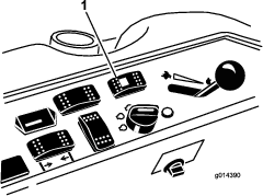
Raising and Lowering the Mower/Attachment
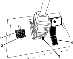
The deck-lift switch raises and lowers the mower deck/attachment (Figure 24). The engine must be running for you to use this switch.
-
To lower the mower deck/attachment, push the switch forward.
-
To raise the mover deck/attachment, push the switch rearward.
Important: Do not continue to hold the switch back after the mower/attachment is fully raised. Doing so will damage the hydraulic system.
Note: To lock the mower deck/attachment in the raised position, raise the deck past the 15 cm (6 inch) position, remove the height-of-cut stop pin (), and insert the pin into the 15 cm (6 inch) height-of-cut position; refer to Adjusting the Height-of-Cut.
Engaging the Power Takeoff (PTO)
The power-takeoff (PTO) switch starts and stops the mower blades and some powered attachments.
-
If the engine is cold, allow the engine to warm up 5 to 10 minutes before engaging the PTO.
-
While seated in the seat, ensure that the traction pedal is in the NEUTRAL position and that the engine is at full throttle.
-
Pull up the PTO switch to engage it (Figure 25).
Disengaging the PTO
To disengage, push the PTO switch to the OFF position.
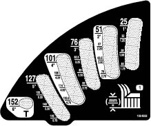
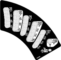
Adjusting the Height-of-Cut
The height-of-cut is adjusted from 2.5 to 15.8 cm (1 to 6 inches) in 6 mm (1/4 inch) increments by relocating the stop pin into different hole locations.
-
With the engine running, push back the deck-lift switch until the mower deck is fully raised and release the switch immediately (Figure 26).
-
Rotate the stop pin until the nub on it lines up with the slots in the holes in the height-of-cut bracket and remove it (Figure 26).
-
Select a hole in the height-of-cut bracket corresponding to the height-of-cut desired, insert the pin, and rotate it down to lock it in place (Figure 26).
Note: There are 4 rows of hole positions (Figure 26). The top row gives you the height of cut listed above the pin. The second row down gives you the height listed plus 6 mm (1/4 inch). The third row down gives you the height listed plus 12 mm (1/2 inch). The bottom row gives you the height listed plus 18 mm (3/4 inch). For the 15.8 cm (6 inch) position, there is only 1 hole, located in the second row. This does not add 6 mm (1/4 inch) to the 15.8 cm (6 inch) position.
-
Adjust the anti-scalp rollers and skids as required.
Selecting the Steering Mode
4-Wheel Drive Only Machines
For maximum trimming and minimum turf damage, always operate the machine in 4-wheel steering. However, to transport the machine on roads or trails, you can switch the machine to 2-wheel steering.
Switching from Four-Wheel Steering to Two-Wheel Steering
Press the steering-selector switch (Figure 27) to the forward position. If the wheels are not aligned in the forward position, the green light flashes and the machine remains in 4-wheel steering until the 4 tires are directed straight ahead. You should turn the steering wheel slowly to straighten out the wheels until the green light ceases to flash and remains on. When the switch light is continuously green, the machine is in 2-wheel steering.
Note: Turning the steering wheel too quickly may cause steering misalignment.
Switching from Two-Wheel Steering to Four-Wheel Steering
Press the steering-selector switch (Figure 27) to the rearward position. If the front wheels are not aligned in the forward position, the green light flashes and the machine remains in 2-wheel steering until the 4 tires are directed straight ahead. You should turn the steering wheel slowly to straighten out the wheels until the green light ceases to flash and remains off. When the switch light is continuously off, the machine is in 4-wheel steering.
Note: Turning the steering wheel too quickly may cause steering misalignment.
Note: If the steering system is misaligned after repeated 2-wheel steering to 4-wheel steering engagements, refer to Correcting the Steering Misalignment.
Operating Tips
Fast Throttle Setting/Ground Speed
To maintain enough power for the machine and deck while mowing, operate the engine at the FAST throttle position and adjust your ground speed for conditions. Decrease the ground speed as the load on the cutting blades increases; and increase the ground speed as the load on the blades decreases.
Mowing Direction
Alternate mowing direction to avoid making ruts in the turf over time. This also helps disperse clippings, which enhances decomposition and fertilization.
Cutting Speed
To improve cut quality, use a slower ground speed.
Avoid Cutting Too Low
If the cutting width of the mower is wider than the mower you previously used, raise the cutting height to ensure that uneven turf is not cut too short.
Select the Proper Height-of-Cut Setting to Suit Conditions
Remove approximately 25 mm (1 inch) or no more than 1/3 of the grass blade when cutting. In exceptionally lush and dense grass, you may need to slow down the forward speed and/or raise the height-of-cut to the next higher setting.
Important: If you are cutting more than 1/3 of the grass blade, or are mowing in sparse long grass or dry conditions, use the flat sail of the blades to reduce air-borne chaff, debris, and strain on the deck-drive components.
Long Grass
If you allow the grass to grow slightly longer than normal, or if it contains a high degree of moisture, raise the cutting height higher than usual and cut the grass at this setting. Then cut the grass again using the lower, normal setting.
Keep the Mower Clean
Clean clippings and dirt from the underside of the mower after each use. If grass and dirt build up inside the mower, cutting quality will eventually become unsatisfactory.
To reduce the risk of fire hazard, keep the engine, muffler, battery compartment, parking brake, cutting units, and fuel storage compartment free of grass, leaves, or excessive grease. Clean up any spilled oil or fuel.
Blade Maintenance
Maintain a sharp blade throughout the cutting season, because a sharp blade cuts cleanly without tearing or shredding the grass blades. Tearing and shredding turns grass brown at the edges, which slows growth and increases the chance of disease. Check the blades daily for sharpness and for any wear or damage. Sharpen the blades as necessary. If a blade is damaged or worn, replace it immediately with a genuine Toro replacement blade. Refer to Blade Maintenance.
After Operation
After Operation Safety
-
Clean grass and debris from the cutting units, mufflers, and engine compartment to help prevent fires. Clean up oil or fuel spills.
-
If the cutting units are in the transport position, use the positive mechanical lock (if available) before you leave the machine unattended.
-
Allow the engine to cool before storing the machine in any enclosure.
-
Shut off the fuel before storing or transporting the machine.
-
Never store the machine or fuel container where there is an open flame, spark, or pilot light, such as on a water heater or on other appliances.
-
Keep all parts of the machine in good working condition and all hardware tightened, especially blade-attachment hardware.
-
Replace all worn or damaged decals.
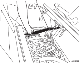
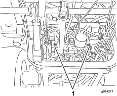
Pushing the Machine by Hand
If the machine stalls or runs out of fuel, you may need to push it. You must first open both of the hydraulic bypass valves.
Important: Always push the machine by hand and never a long distance. Never tow the machine, because damage to the hydraulic system may occur.
Pushing the Machine
-
Disengage the power takeoff (PTO), turn the key to the OFF position, and engage the parking brake.
-
Remove the key from the key switch. You must open both bypass valves.
-
Lift the seat.
-
Rotate each bypass valve counterclockwise 1 turn (Figure 28).
Note: This allows hydraulic fluid to bypass the pump, enabling the wheels to turn.
Important: Do not rotate the bypass valves more than 1 turn. This prevents the valves from coming out of the body and causing fluid to run out.
-
Disengage the parking brake before pushing the machine.
Hauling the Machine
-
Use care when loading or unloading the machine into a trailer or a truck.
-
Use full-width ramps for loading the machine into a trailer or a truck.
-
Tie the machine down securely using straps, chains, cable, or ropes. Both front and rear straps should be directed down and outward from the machine.
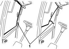
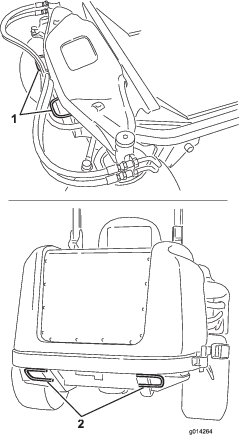
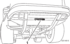
Locating the Tie-Down Points
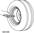
There are tie downs located at the front and rear sides of the machine (Figure 29).
Note: Use properly-rated DOT-approved straps in 4 corners to tie down the machine.
-
2 on the front of the operator's platform
-
Rear tire
Maintenance
Note: Determine the left and right sides of the machine from the normal operating position.
Recommended Maintenance Schedule(s)
| Maintenance Service Interval | Maintenance Procedure |
|---|---|
| After the first 10 hours |
|
| After the first 50 hours |
|
| After the first 200 hours |
|
| Before each use or daily |
|
| Every 50 hours |
|
| Every 100 hours |
|
| Every 150 hours |
|
| Every 200 hours |
|
| Every 250 hours |
|
| Every 400 hours |
|
| Every 800 hours |
|
| Every 1,500 hours |
|
| Every 2 years |
|
Important: Refer to your engine owner's manual for additional maintenance procedures. A detailed Service Manual is also available for purchase from your Authorized Toro Distributor.
Note: To obtain an electrical schematic or a hydraulic schematic for your machine, visit www.Toro.com.
Pre-Maintenance Procedures
Pre-Maintenance Safety
-
Before adjusting, cleaning, repairing, or leaving the machine, do the following:
-
Park the machine on a level surface.
-
Move the throttle switch to the low-idle position.
-
Disengage the cutting units.
-
Lower the cutting units.
-
Ensure that the traction is in neutral.
-
Engage the parking brake.
-
Shut off the engine and remove the key.
-
Wait for all moving parts to stop.
-
Allow machine components to cool before performing maintenance.
-
-
If the cutting units are in the transport position, use the positive mechanical lock (if available) before you leave the machine unattended.
-
If possible, do not perform maintenance while the engine is running. Keep away from moving parts.
-
Use jack stands to support the machine or components when required.
-
Carefully release pressure from components with stored energy.
Preparing the Machine for Maintenance
-
Ensure that the PTO is disengaged.
-
Park the machine on a level surface.
-
Engage the parking brake.
-
Lower the mower deck(s) if necessary.
-
Shut off the engine and wait for all moving parts to stop.
-
Turn the ignition key to the STOP position and remove it.
-
Allow machine components to cool before performing maintenance.
Using the Hood-Prop Rod
-
Release the hood latches.
-
Lift up the hood until you can position the prop rod behind the frame tube (Figure 31).
-
Lower the hood until the prop rod is in front of and resting against the frame tube.
-
To lower the hood, raise the hood until you can raise the prop rod above the frame tube, then lower the hood.
-
Secure the hood latches.
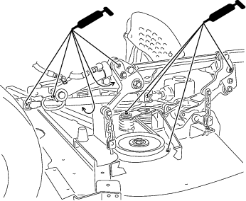
Lubrication
Greasing the Bearings and Bushings
| Maintenance Service Interval | Maintenance Procedure |
|---|---|
| Every 50 hours |
|
The machine has grease fittings that you must lubricate regularly with No. 2 lithium grease. Lubricate the grease fittings immediately after every washing, regardless of interval specified.
-
Wipe the grease fittings clean so that foreign matter cannot be forced into the bearing or bushing (Figure 33).
-
Pump the grease into the fittings.
-
Wipe off any excess grease.
Note: To access the grease fittings for the rear-steering linkage, remove the storage compartment.
Note: Raise the machine off the floor with a jack and secure it with jack stands to allow better grease migration through both the upper and lower king-pin bushings. You should see grease purging out of both the top and the bottom of the axle casting/bushing assembly areas of all 4 kingpin assemblies (Figure 34).
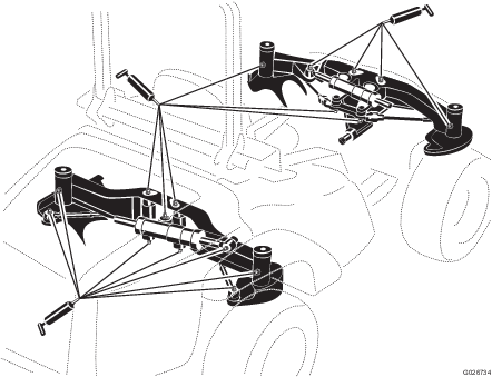
Note: The bearing life can be negatively affected by improper washing procedures. Do not wash the machine when it is still hot and avoid directing high-pressure or high-volume spray at the bearings or seals.
Engine Maintenance
Engine Safety
-
Shut off the engine before checking the oil or adding oil to the crankcase.
-
Do not change the governor speed or overspeed the engine.
Servicing the Air Cleaner
| Maintenance Service Interval | Maintenance Procedure |
|---|---|
| Every 400 hours |
|
Check the air-cleaner body for damage that could cause an air leak. Replace a damaged air cleaner. Check the whole intake system for leaks, damage, or loose hose clamps.
Service the air-cleaner filter only when the service indicator (Figure 34) requires it. Changing the air filter before it is necessary only increases the chance of dirt entering the engine when you remove the filter.
Important: Be sure that the cover is seated correctly and seals with the air-cleaner body.
-
Release the latch securing the air-cleaner cover to the air-cleaner body (Figure 34).
-
Remove the cover from the air-cleaner body. Before removing the filter, use clear and dry low-pressure air (276 kPa or 40 psi) to help remove large accumulations of debris packed between outside of the filter and the canister. Avoid using high-pressure air, which could force dirt through the filter into the intake tract.
Note: This cleaning process prevents debris from migrating into the intake when you remove the filter.
-
Remove and replace the filter.
Important: Do not clean the used element to prevent damaging the filter media. Inspect the new filter for shipping damage, checking the sealing end of the filter and the body. Do not use a damaged element. Insert the new filter by applying pressure to the outer rim of the element to seat it in the canister. Do not apply pressure to the flexible center of the filter.
-
Clean the dirt-ejection port located in the removable cover.
-
Remove the rubber outlet valve from the cover, clean the cavity and replace the outlet valve.
-
Install the cover orienting the rubber outlet valve in a downward position—approximately between the 5 o’clock to 7 o’clock positions when viewed from the end.
-
Secure the latch.
Checking the Engine-Oil Level
| Maintenance Service Interval | Maintenance Procedure |
|---|---|
| Before each use or daily |
|
The engine is shipped with oil in the crankcase; however, check the oil level before and after you start the engine for the first time.
The crankcase capacity is approximately 5.2 L (5.5 US qt) with the filter.
Use high-quality engine oil that meets the following specifications:
-
API Classification Level Required: CH-4, CI-4 or higher
-
Preferred oil: SAE 15W-40 (above 0°F)
-
Alternate oil: SAE 10W-30 or 5W-30 (all temperatures)
Toro Premium Engine Oil is available from your distributor in either 15W-40 or 10W-30 viscosity.
-
Perform the pre-maintenance procedure; refer to Preparing the Machine for Maintenance.
-
Open the hood.
-
Remove the dipstick, wipe it clean, and install it (Figure 35).
-
Remove dipstick and check the oil level on dipstick. The oil level should be up to the FULL mark.
-
If the oil level is below the FULL mark, remove the fill cap (Figure 35) and add oil until level reaches the FULL mark on dipstick. Do not overfill.
Important: Be sure to keep the engine oil level between the upper and lower limits on the oil gauge. Engine failure may occur as a result of over filling or under filling the engine oil and running the engine.
-
Install the oil fill cap and close the hood.
Changing the Engine Oil and Filter
| Maintenance Service Interval | Maintenance Procedure |
|---|---|
| After the first 50 hours |
|
| Every 150 hours |
|
-
Remove the drain plug (Figure 36) and let the oil flow into a drain pan.
-
When the oil stops, install the drain plug.
-
Remove the oil filter (Figure 36).
-
Apply a light coat of clean oil to the new filter seal.
-
Install the replacement oil filter to the filter adapter. Turn the oil filter clockwise until the rubber gasket contacts the filter adapter, then tighten the filter an additional 1/2 turn.
Important: Do not over-tighten the filter.
-
Add oil to the crankcase; refer to Checking the Engine-Oil Level.
Adjusting the Throttle
-
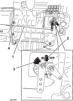
Move the throttle lever forward to the front of the control panel slot and then move it back approximately 3 mm (1/8 inch) into the FAST idle position.
-
Check the position of the speed control lever on the fuel-injection pump. The speed-control lever should contact the high-speed screw when the throttle-control lever is in the FAST (detent) position (Figure 37).
-
If necessary, adjust the position of the jam nuts on the throttle-control cable until the speed-control lever contacts the high-speed screw when the throttle-control lever is in the FAST (detent) position (Figure 37).
-
Ensure that the cable jam nuts are fully tightened after the adjustment.
Fuel System Maintenance
Note: Refer to Recommended Fuel for proper fuel recommendations.
Danger
Under certain conditions, diesel fuel and fuel vapors are highly flammable and explosive. A fire or explosion from fuel can burn you and others and can cause property damage.
-
Use a funnel and fill the fuel tank outdoors, in an open area, when the engine is off and is cold. Wipe up any fuel that spills.
-
Do not fill the fuel tank completely full. Add fuel to the fuel tank until the level is to the bottom of the filler neck.
-
Never smoke when handling fuel and stay away from an open flame or where a spark my ignite fuel fumes.
-
Store fuel in a clean, safety-approved container and keep the cap in place.
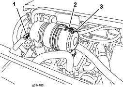
Servicing the Water Separator
| Maintenance Service Interval | Maintenance Procedure |
|---|---|
| Every 400 hours |
|
Drain the water or other contaminants from the water separator (Figure 38) daily.
-
Place a clean container under the fuel filter.
-
Loosen the drain plug on the bottom of the filter canister (Figure 38).

-
Clean the area where the filter canister mounts.
-
Remove the filter canister and clean the mounting surface.
-
Lubricate the gasket on the filter canister with clean oil.
-
Install the filter canister by hand until the gasket contacts mounting surface, then rotate it an additional 1/2 turn.
-
Tighten the drain plug on the bottom of the filter canister.
Bleeding the Fuel System
You must bleed the fuel system before starting the engine if any of the following have occurred:
-
Initial start up of a new machine
-
The engine has ceased running due to lack of fuel.
-
Maintenance has been performed upon fuel system components (i.e., filter replaced, separator serviced, etc.)
-
Perform the pre-maintenance procedure; refer to Checking the Tire Pressure and ensure that the fuel tank is at least half full.
-
Open the hood and secure it with the prop rod.
-
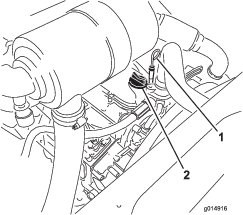
Open the air-bleed screw on the fuel-injection pump (Figure 39) with a 12 mm wrench.
-
Turn the key in the ignition switch to the ON position. The electric fuel pump will begin operation, thereby forcing air out around the air bleed screw. Leave the key in the ON position until a solid stream of fuel flows out around the screw.
-
Tighten the screw and turn the key to the OFF position.
Note: The engine should start after you perform this procedure. However, if engine does not start, air may be trapped between injection pump and the injectors; refer to Bleeding Air from the Fuel Injectors.
Bleeding Air from the Fuel Injectors
Note: Use this procedure only if the fuel system has been purged of air through normal priming procedures and the engine does not start; refer to Bleeding the Fuel System.
-
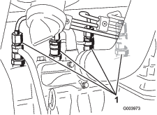
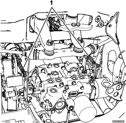
Loosen the pipe connection to the No. 1 nozzle and holder assembly (Figure 40).
-
Turn the key in the key switch to the ON position and watch the fuel flow around the connector. When you observe a solid flow of fuel, turn the key to the OFF position.
-
Tighten the pipe connector securely.
-
Repeat steps 1 through 3 for the remaining nozzles.
Cleaning the Fuel Tank
| Maintenance Service Interval | Maintenance Procedure |
|---|---|
| Every 2 years |
|
Drain and clean the fuel tank every 2 years. Also, remove and clean the in-line strainers after draining the tank. Use clean diesel fuel to flush out the tank.
Important: Drain and clean the tank if the fuel system becomes contaminated or if you store the machine for an extended period of time.
Checking the Fuel Lines and Connections
| Maintenance Service Interval | Maintenance Procedure |
|---|---|
| Every 400 hours |
|
Inspect the fuel lines for deterioration, damage, chaffing, or loose connections.
Electrical System Maintenance
Electrical System Safety
-
Disconnect the battery before repairing the machine. Disconnect the negative terminal first and the positive last. Connect the positive terminal first and the negative last.
-
Charge the battery in an open, well-ventilated area, away from sparks and flames. Unplug the charger before connecting or disconnecting the battery. Wear protective clothing and use insulated tools.
Warning
Battery posts, terminals, and related accessories contain lead and lead compounds, chemicals known to the State of California to cause cancer and reproductive harm. Wash hands after handling.
Servicing the Battery
| Maintenance Service Interval | Maintenance Procedure |
|---|---|
| Every 50 hours |
|
Keep the top of the battery clean. If you store the machine in a location where temperatures are extremely high, the battery will run down more rapidly than if the machine is stored in a location where temperatures are cool.
Keep the top of the battery clean by washing it periodically with a brush dipped in ammonia or bicarbonate of soda solution. Flush the top surface with water after cleaning it. Do not remove the fill caps while cleaning the battery.
The battery cables must be tight on the terminals to provide good electrical contact.
If corrosion occurs at the terminals, disconnect the cables, negative (-) cable first, and scrape the clamps and terminals separately. Connect the cables, positive (+) cable first, and coat the terminals with petroleum jelly.
Warning
Battery terminals or metal tools could short against metal machine components, causing sparks. Sparks can cause the battery gasses to explode, resulting in personal injury.
-
When removing or installing the battery, do not allow the battery terminals to touch any metal parts of the machine.
-
Do not allow metal tools to short between the battery terminals and metal parts of the machine.
Storing the Battery
If you store the machine for more than 30 days, remove the battery and charge it fully. Either store it on a shelf or on the machine. Leave the cables disconnected if you store it on the machine. Store the battery in a cool atmosphere to avoid quick deterioration of the charge in the battery. To prevent the battery from freezing, ensure that it is fully charged. The specific gravity of a fully charged battery is 1.265 to 1.299.
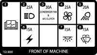
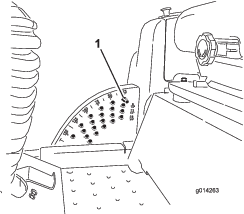
Checking the Fuses
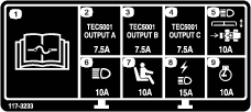
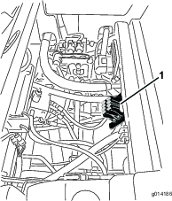
If the machine stops or has other electrical-system issues, check the fuses. Grasp each fuse in turn and remove them 1 at a time, checking to see if any are blown. If you need to replace a fuse, always use the same type and amperage rated fuse as the 1 you are replacing; otherwise, you could damage the electrical system (refer to the decal next to the fuses for a diagram of each fuse and its amperage).
The traction-unit fuses are located under the seat (Figure 41).
The cab fuses are located in the fuse box on the cab headliner (Figure 42).
Drive System Maintenance
Checking the Tire Pressure
| Maintenance Service Interval | Maintenance Procedure |
|---|---|
| Every 50 hours |
|
Maintain the air pressure in the front and rear tires. The correct air pressure is 172 kPa (25 psi) in the rear tires and 103 kPa (15 psi) in the front tires. If a cab is installed on the machine, the front and rear tires should be inflated to 172 kPa (25 psi). Uneven tire pressure can cause an uneven cut. Check the tires when they are cold to get the most accurate pressure reading.
Correcting the Steering Misalignment
-
Press the steering-selector switch rearward 4-wheels steering position (Figure 44).
-
On a paved or dirt surface, turn the steering wheel to the left or right and continue turning until all 4 wheels have stopped turning. Automatic synchronization of the wheel alignment should occur.
Important: Doing this procedure on turf can result in turf damage directly under each of the turning tires.
Cooling System Maintenance
Cooling System Safety
-
Swallowing engine coolant can cause poisoning; keep out of reach from children and pets.
-
Discharge of hot, pressurized coolant or touching a hot radiator and surrounding parts can cause severe burns.
-
Always allow the engine to cool at least 15 minutes before removing the radiator cap.
-
Use a rag when opening the radiator cap, and open the cap slowly to allow steam to escape.
-
Checking the Cooling System
| Maintenance Service Interval | Maintenance Procedure |
|---|---|
| Before each use or daily |
|
Danger
The rotating fan and drive belt can cause personal injury.
-
Do not operate the machine without the covers in place.
-
Keep your fingers, hands and clothing clear of rotating fan and drive belt.
-
Shut off the engine and remove the ignition key before performing maintenance.
The cooling system is filled with a 50/50 solution of water and permanent ethylene glycol anti freeze. Check the level of the coolant in the expansion tank at the beginning of each day before starting the engine. The capacity of the cooling system is 7.5 L (6 US qt).
-
Check the level of the coolant in the expansion tank (Figure 45). The coolant level should be between the marks on the side of the tank.
-
If coolant level is low, remove the expansion tank cap and replenish the system. Do not overfill.
-
Install the expansion-tank cap.
Cleaning the Radiator
| Maintenance Service Interval | Maintenance Procedure |
|---|---|
| Before each use or daily |
|
| Every 200 hours |
|
| Every 1,500 hours |
|
| Every 2 years |
|
Keep the radiator clean to prevent the engine from overheating.
Note: If the attachment or engine shuts off due to overheating, first check the radiator for an excessive buildup of debris.
-
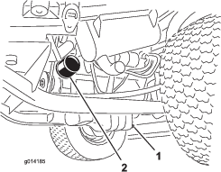
Open the hood and secure the prop rod.
-
Loosen the flange nut securing the clean-out cover to the underside of the rear frame (Figure 46). Rotate the cover to the side to expose the clean-out hole in the frame.
-
Working from the fan side of the radiator, blow out debris with low-pressure (50 psi) compressed air (do not use water). Repeat this step from the front of the radiator, again from the fan side.
-
After you have thoroughly cleaned the radiator, remove any debris from the channel at the radiator base and around the frame.
-
Clean the engine compartment and the brake linkage.
-
Close the clean-out cover and secure the flange nut.
-
Close the hood.
Brake Maintenance
Adjusting the Service Brakes
Adjust the service brakes when there is more than 25 mm (1 inch) of free travel of the brake pedal, or when the brakes do not work effectively. Free travel is the distance that the brake pedal moves before you feel braking resistance.
Note: Use the wheel-motor backlash to rock the drums back and forth to ensure that the drums are free prior to and after adjustment.
-
To reduce free travel of the brake pedals, tighten the brakes by loosening the front nut on the threaded end of the brake cable (Figure 47).
-
Tighten the rear nut to move the cable backward until brake pedals have 1.27 to 1.9 cm (1/2 to 3/4 inch) of free travel before the wheels lock up.
-
Tighten the front nuts, ensuring that both cables actuate the brakes simultaneously.
Adjusting the Parking Brake
If the parking brake fails to engage, adjust the brake pawl.
-
Loosen the 2 screws securing the parking-brake pawl to the frame (Figure 48).
-
Press the parking brake pedal forward until the brake detent completely engages on the brake pawl (Figure 48).
-
Tighten the 2 screws locking the adjustment.
-
Press the brake pedal to release the parking brake.
-
Check the adjustment and adjust it as required.
Belt Maintenance
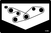
Checking the Alternator Belt
| Maintenance Service Interval | Maintenance Procedure |
|---|---|
| After the first 10 hours |
|
| Every 100 hours |
|
-
Open the hood and secure the prop rod.
-
Check the tension of the alternator belt by pressing it (Figure 49) midway between the alternator and the crankshaft pulleys with 10 kg (22 lb) of force.
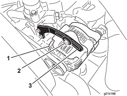
The belt should deflect 11 mm (7/16 inch). If the deflection is incorrect, proceed to step 3. If it is correct, you are finished with this procedure.
-
Loosen the bolt securing the brace to the alternator (Figure 49) and the alternator pivot bolt.
-
Insert a pry bar between the alternator and the engine and pry on the alternator.
-
When you achieve the proper tension, tighten the alternator, brace, and pivot bolts to secure the adjustment.
Controls System Maintenance
Adjusting the Traction Drive for Neutral
Note: If the machine has recently had the hydraulic fluid changed or the traction motors or hoses replaced, work out any air trapped in the system prior to performing this procedure. To do this, operate the machine in forward and reverse for a few minutes and then replenish the oil as required.
Note: When positioned on a level surface, the machine must not creep when you release the traction pedal.
-
Park the machine on a level surface, engage the parking brake, lower the cutting unit to the floor, and shut off the engine.
-
Jack up the rear of the machine until the rear tires are off the shop floor. Support the machine with jack stands to prevent it from falling.
Note: On 4-wheel-drive models, the front tires must also be off the shop floor and supported by jack stands.
Warning
The engine must be running so that you can perform this adjustment. This could cause personal injury.
Keep your hands, feet, face, and other body parts away from any hot parts of the engine and any rotating parts.
-
Start the engine, set the throttle to the SLOW position, and observe which direction the rear tires rotate.
Important: Make sure that the traction pedal is in the NEUTRAL position.
-
If the left rear tire is rotating, loosen the jam nuts on the left side transmission control rod (Figure 50).
Note: The forward end of the control rod has a left-hand thread. The rear end of the rod, which is connected to the transmission, has a right-hand thread.
-
If the left rear tire is rotating in reverse, lengthen the rod by slowly turning the rod counterclockwise (as viewed from the front) until the left rear tire stops rotating or has minimal rotation in reverse.
-
If the left rear tire is rotating forward, shorten the rod by slowly turning the rod clockwise (as viewed from the front) until the left rear tire stops rotating.
-
-
Move the throttle to the FAST position. Make sure that the wheel remains stopped or has minimal rotation in reverse. Adjust it as required.
-
Tighten the jam nuts.
-
Repeat the procedure for the right rear tire, if required, by using the right-side transmission control rod.
-
Shut off the engine, remove the jack stands, and lower the machine to the shop floor.
-
Test drive the machine to make sure that it does not creep.
Adjusting the Maximum Ground Speed
-
Park the machine on a level surface, disengage the PTO, release the traction pedal to the NEUTRAL position, and engage the parking brake.
-
Move the throttle lever to the SLOW position, shut off the engine, remove the key from the key switch, and wait for all moving parts to stop before leaving the operating position.
-
Loosen the jam nut on the stop bolt for the traction pedal (Figure 51).
-
Adjust the stop bolt all the way in (away from the traction pedal).
-
Using your hand, push the traction pedal all the way forward, with light pressure, until it stops and hold it there.
Note: Maintain only light pressure on the pedal when pushing it to the full forward position.
-
With the seat in the raised position, verify that you are not over loading the linkage by making sure the transmission does not move when you press the pedal to the stop.
-
Adjust the stop bolt out (toward the traction pedal) until there is a gap of 1.5 mm (0.060 inch) between the head of the stop bolt and the bottom of the traction pedal.
-
Tighten the jam nut to secure the stop bolt in place.
-
To change the reverse speed, you can adjust the reverse stop bolt. To increase the reverse speed, adjust the stop bolt in; to decrease the reverse speed, adjust the stop bolt out.
Hydraulic System Maintenance
The reservoir is filled at the factory with approximately 17 L (18 US qt) of high-quality tractor transmission/hydraulic fluid. The recommended replacement fluid is as follows:
| Toro Premium Transmission/Hydraulic Tractor Fluid (Available in 5 gallon pails or 55 gallon drums. See parts catalog or Toro Distributor for part numbers.) |
Alternate fluids: If the Toro fluid is not available, you can use Mobil® 424 hydraulic fluid.
Note: Toro will not assume responsibility for damage caused by improper substitutions.
Note: Many hydraulic fluids are almost colorless, making it difficult to spot leaks. A red dye additive for the hydraulic system oil is available in 20 ml (2/3 oz) bottles. A bottle is sufficient for 15 to 22 L (4 to 6 US gallons) of hydraulic fluid. Order Part No. 44-2500 from your Authorized Toro Distributor.
Hydraulic System Safety
-
Ensure that all hydraulic-fluid hoses and lines are in good condition and all hydraulic connections and fittings are tight before applying pressure to the hydraulic system.
-
Keep your body and hands away from pinhole leaks or nozzles that eject high-pressure hydraulic fluid.
-
Use cardboard or paper to find hydraulic leaks.
-
Safely relieve all pressure in the hydraulic system before performing any work on the hydraulic system.
-
Seek immediate medical attention if fluid is injected into skin. Injected fluid must be surgically removed within a few hours by a doctor.
Checking the Hydraulic System
| Maintenance Service Interval | Maintenance Procedure |
|---|---|
| Before each use or daily |
|
-
Park the machine on a level surface, engage the parking brake, lower the cutting deck, shut off the engine, and remove the key from the key switch.
-
Release the traction pedal to the NEUTRAL position and start the engine. Run engine at lowest possible speed to purge the system of air. Do not engage the PTO.
-
Raise the deck to extend lift cylinders, shut off the engine, and remove the key.
-
Remove the hydraulic-fill cap (Figure 52) from the filler neck.
-
Remove the dipstick and wipe it with a clean rag (Figure 52).
-
Screw the dipstick all the way into the filler neck; then remove it and check level of fluid (Figure 52).
If level is not within notched area of the dipstick, add enough high-quality hydraulic fluid to raise level to within the notched area. Do not overfill.
-
Replace the dipstick and thread the fill cap finger-tight onto the filler neck.
-
Check all hoses and fittings for leaks.
Changing the Hydraulic Fluid and Filter
| Maintenance Service Interval | Maintenance Procedure |
|---|---|
| After the first 200 hours |
|
| Every 800 hours |
|
-
Disengage the PTO, release the traction pedal to the NEUTRAL position and engage the parking brake.
-
Move the throttle lever to the SLOW position, shut off the engine, remove the key, and wait for all moving parts to stop before leaving the operating position.
-
Place a large pan under the hydraulic reservoir and transmission case and remove the plugs tp drain all the hydraulic fluid (Figure 53).
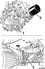
-
Clean the area around the hydraulic-fluid filter and remove it (Figure 53).
-
Immediately install a new hydraulic-fluid filter.
-
Install the hydraulic reservoir and transmission case drain plugs.
-
Fill the reservoir to the proper level (approximately 17 L or 18 US qt); refer to Checking the Hydraulic System.
-
Start the engine and check for leaks. Allow the engine to run for about 5 minutes, then shut it off.
-
After 2 minutes, check the level of the hydraulic fluid; refer to Checking the Hydraulic System.
Cab Maintenance
Filling the Washer-Fluid Bottle
-
Perform the pre-maintenance procedure; refer to Preparing the Machine for Maintenance.
-
Open the hood and locate the washer-fluid bottle (Figure 54).
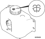
-
Fill the bottle with washer fluid as needed.
-
Close the hood.
Cleaning the Cab Air Filters
| Maintenance Service Interval | Maintenance Procedure |
|---|---|
| Every 250 hours |
|
-
Remove the screws and grates from over both the in-cab and rear cab air filters (Figure 55).
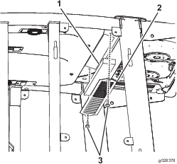
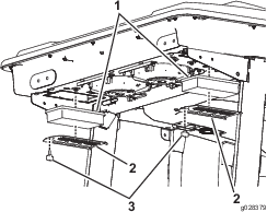
-
Clean the filters by blowing clean, oil-free, compressed air through them.
Important: If either filter has a hole, tear, or other damage, replace it.
-
Install the filters and grate, securing them with the thumb screws.
Cleaning the Air-Conditioning Coil
| Maintenance Service Interval | Maintenance Procedure |
|---|---|
| Every 50 hours |
|
-
Perform the pre-maintenance procedure; refer to Preparing the Machine for Maintenance.
-
Lift the 4 tabs on the air-conditioning screen (Figure 57) and remove the screen from the top of the cab.
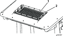
-
Disconnect the plug and cord for the fans from the outlet (Figure 58).
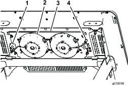
-
Remove the 2 knobs that secure the fan-panel assembly and fans to the underside of the cab top (Figure 58) and remove the assembly.
-
Clean the screen, air-conditioning duct, fans, and fan panel using low-pressure air no greater than 276 kPa (40 psi).
Important: Do not use water to clean the condenser because moisture on the components attracts dirt and dust, which make the components more difficult to clean.
-
Install the fan-panel assembly and fans to the underside of the cab top with the 2 knobs that you loosened and removed in step 4.
-
Connect the cord for the fans that you disconnected in step 3 into the outlet.
-
Install the air-conditioning screen in the opening in the top of the cab and secure it by closing the 4 tabs on the screen.
Cleaning
Cleaning the Cab
Important: Use care around the cab seals and lights (Figure 59). If you are using a pressure washer, keep the washer wand at least 0.6 m (2 ft) away from the machine. Do not use the pressure washer directly on the cab seals and lights or under the rear overhang.
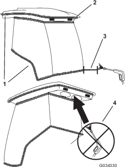
Waste Disposal
Engine oil, batteries, hydraulic fluid, and engine coolant are pollutants to the environment. Dispose of these according to federal, state, and local regulations.
Storage
Servicing the Engine
-
Drain the engine oil from the oil pan and replace the drain plug.
-
Remove and discard the oil filter. Install a new filter.
-
Fill the engine with 3.8 L (4 US qt) of recommended engine oil; refer to Changing the Engine Oil and Filter.
-
Start the engine and run it at idle speed for 2 minutes.
-
Drain the fuel from the fuel tank, fuel lines, pump, filter, and separator. Flush the fuel tank with clean diesel fuel and connect all the fuel lines.
-
Thoroughly clean and service the air-cleaner assembly.
-
Seal the air-cleaner inlet and the exhaust outlet with weatherproof masking tape.
-
Check the oil-filler cap and fuel-tank cap to ensure that they are securely in place.
Servicing the Machine
-
Thoroughly clean the machine, attachment, and engine, paying special attention to the following areas:
-
Radiator and radiator screen
-
Underneath the attachment
-
Under the attachment covers
-
PTO shaft assembly
-
All grease fittings and pivot points
-
Behind the control panel and inside the control box
-
Beneath the seat plate and top of the transmission
-
-
Check and adjust air pressure in the tires; refer to Checking the Tire Pressure.
-
Remove, sharpen, and balance the mower blades. Install the blades and torque the blade fasteners to 115 to 149 N-m (85 to 110 ft-lb).
-
Check all fasteners for looseness and tighten them as necessary.
-
Grease or oil all grease fittings, pivot points, and transmission bypass-valve pins. Wipe off any excess lubricant.
-
Lightly sand and use touch-up paint on painted areas that are scratched, chipped, or rusted. Repair any dents in the metal body.
-
Service the battery and cables as follows:
-
Remove the battery terminals from the battery posts.
-
Clean the battery, terminals, and posts with a wire brush and baking-soda solution.
-
Coat the cable terminals and battery posts with Grafo 112X skin-over grease (Toro Part No. 505-47) or petroleum jelly to prevent corrosion.
-
Slowly charge the battery for 24 hours every 60 days to prevent lead sulfation of the battery.
-