
Note: Install this kit for improving the movement of the machine out of neutral position.
CALIFORNIA
Proposition 65 Warning
Parts needed for this procedure:
| Thrust washer | 1 |
| Sleeve spacer (long) | 1 |
| Sleeve spacer (small) | 1 |
| Bearings | 2 |
Park the machine on a level surface, shut off the engine, engage the parking brake, and remove the key from the switch.
Loosen the lug nuts for the right rear tire.
Raise the right side of the machine with a jack and secure it with a jack stand.
Remove the right rear tire. This allows for easy access for installation.
Locate and remove the existing neutral-arm assembly (Figure 1 and Figure 2).

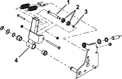
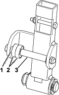
Remove the existing bearings and spacers from the neutral arm (Figure 3).
Install the new bearings and spacers (Figure 3).
Install the neutral-arm assembly into the machine (Figure 2).
Parts needed for this procedure:
| Traction rod | 1 |
| Jam nut (3/8 inch) | 1 |
| Rod-end bearing | 1 |
| Linkage plate | 1 |
| Rubber mount | 2 |
| Plastic mount | 2 |
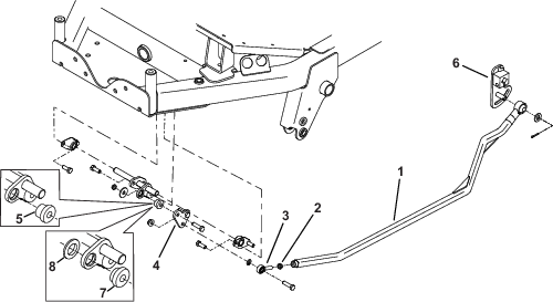
Locate and remove the traction-lever arm (Figure 4).
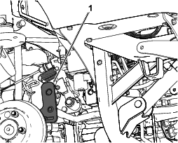
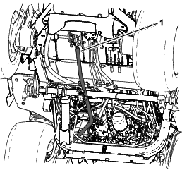
Remove the existing traction rod from the traction-lever arm and the front linkage (Figure 5).
Install the rod-end bearing and jam nut onto the traction rod (Figure 6).
Install the linkage plate and either the rubber or plastic mounts (Figure 6).
Note: Use either the plastic or the rubber mounts for this kit, whichever gives you the best feel when operating the machine. It is recommended that you use the rubber mounts for a machine with a cab as this will help reduce the noise in the cab (Figure 6).
Install the new traction rod to the traction-lever arm and the front linkage (Figure 5 and Figure 6).
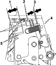
Adjust the tension on the springs as shown in Figure 7.
Adjust the neutral switch as shown in Figure 7.
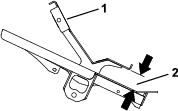
Move the traction pedal to the neutral position, adjust the rod-end bearing by threading it in or out to achieve the dimension shown in Figure 8.
Install the right rear tire.
Note: When positioned on a level surface, the machine must not creep when you release the traction pedal.
Park the machine on a level surface, engage the parking brake, lower the cutting unit to the floor, and shut off the engine.
Jack up the rear of the machine until the rear tires are off the shop floor. Support the machine with jack stands to prevent it from falling.
Note: On 4-wheel-drive models, the front tires must also be off the shop floor and supported by jack stands.
The engine must be running so that you can perform this adjustment. This could cause personal injury.
Keep your hands, feet, face, and other body parts away from any hot parts of the engine and any rotating parts.
Start the engine, set the throttle to the SLOW position, and observe which direction the rear tires rotate.
Important: Make sure that the traction pedal is in the NEUTRAL position.
If the left rear tire is rotating, loosen the jam nuts on the left side transmission control rod (Figure 9).
Note: The forward end of the control rod has a left-hand thread. The rear end of the rod, which is connected to the transmission, has a right-hand thread.
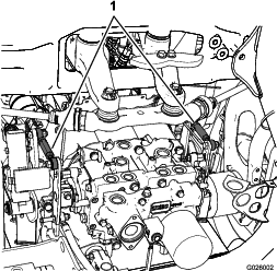
If the left rear tire is rotating in reverse, lengthen the rod by slowly turning the rod counterclockwise (as viewed from the front) until the left rear tire stops rotating or has minimal rotation in reverse.
If the left rear tire is rotating forward, shorten the rod by slowly turning the rod clockwise (as viewed from the front) until the left rear tire stops rotating.
Move the throttle to the FAST position. Make sure that the wheel remains stopped or has minimal rotation in reverse. Adjust it as required.
Tighten the jam nuts.
Repeat the procedure for the right rear tire, if required, by using the right-side transmission control rod.
Shut off the engine, remove the jack stands, and lower the machine to the shop floor.
Test drive the machine to make sure that it does not creep.