CALIFORNIA
Proposition 65 Warning
Important: Cap or plug any disconnected hydraulic hoses, tubes, or component ports to prevent contaminating the system.
Park the machine on a level surface.
Engage the parking brake.
Lower the loader arms.
Shut off the engine and remove the key.
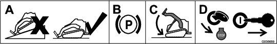
Open the hood and secure the prop rod.
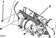
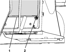
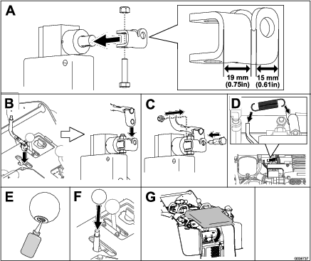
Remove the cover plate (Figure 2).
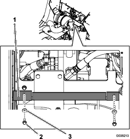
Remove the 2 bolts and 2 washers securing the rubber baffle and lower the baffle (Figure 3).
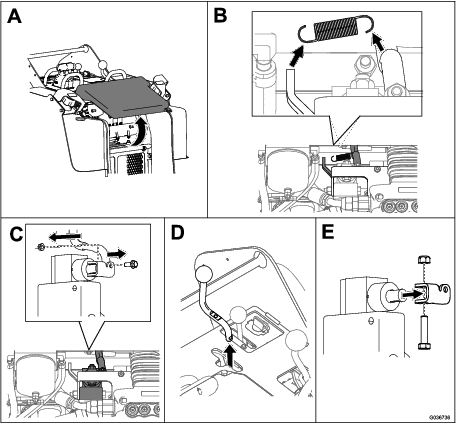
Lift the cushion pad.
Remove the auxiliary handle as shown in Figure 4. Retain all parts for later installation.
 |
Remove the radiator screen at the back of the machine and locate the drain plug at the bottom right corner.
Place a large drain pan beneath the drain plug orifice and unthread the plug (Figure 5).
Loosen the upper hose clamp and remove the hose from the outlet on the radiator (Figure 6).
Temporarily plug the outlet on the radiator and drain the detached hose.
Loosen the lower hose clamp and remove the hose from the outlet on the engine.
Note: Retain the hose clamps for installation in Installing the New Radiator Hose, Outlet and Gasket.
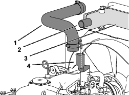
Remove the radiator hose from the machine (Figure 6).
Note: You may discard the removed hose.
Remove the 2 mounting bolts from the outlet on top of the engine (Figure 6).
Remove the existing straight-end outlet and gasket from the engine.
Note: You may discard the removed straight-end outlet, gasket, and associated hardware.
Parts needed for this procedure:
| Outlet | 1 |
| Gasket | 1 |
| M8 Bolt | 2 |
| Radiator hose | 1 |
Install the radiator drain plug (Figure 7).
Note: Ensure that drain plug does not leak; you may need to apply thread sealant to the drain plug.
Install the radiator screen.
Align the gasket and outlet with the mounting holes and port on top of the engine, with the angled end of the outlet facing the right side of the machine (Figure 8).
Thread the bolts into the mounting holes and tighten the bolts to 18 to 20 N-m (13 to 15 ft-lb).
Using the previously removed hose clamps, install the lower end of the radiator hose to the angled-end outlet and tighten the hose clamp (Figure 17).
Install the upper end of the radiator hose to the straight-end outlet on the radiator and tighten the hose clamp (Figure 8).
Remove the radiator cap and fill the tank to the neck with a 50/50 solution of water and permanent ethylene-glycol antifreeze. Refer to your Operator’s Manual.
Check the level of coolant in the expansion tank and add coolant until it reaches the side mark. Refer to your Operator’s Manual.
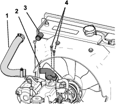
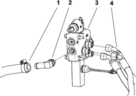
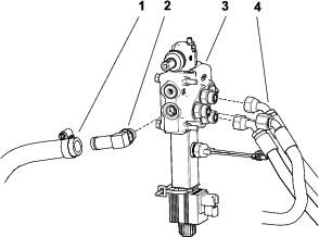
Remove the 2 hoses attached to the tee-fitting in the front of the auxiliary valve (Figure 9).
Temporarily plug the detached hoses.
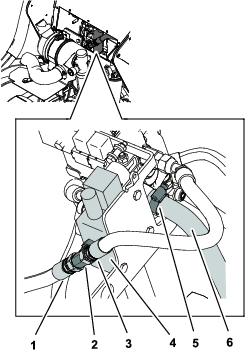
Mark the 3 pressure hoses and ports shown in Figure 10 with their corresponding port locations so that you can install them into the correct ports later.
Disconnect the 3 pressure hoses from the straight fittings on the side of the auxiliary valve (Figure 10).
Note: You may also need to remove the clamp plate on the left side of the machine to remove the auxiliary hoses from the valve. Retain it for later installation.
Disconnect the return hose attached to the elbow fitting at the back of the auxiliary valve by loosening the hose clamp (Figure 10).
Temporarily plug the return hose.
Remove the elbow fitting from the back of the auxiliary valve (Figure 10).
Disconnect the ball switch plug from the wire harness socket.
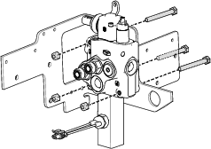
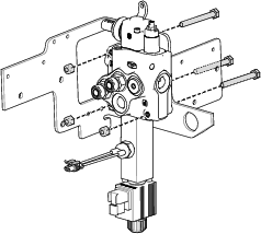
Remove the 3 bolts and nuts securing the auxiliary valve to the bracket (Figure 11).
Remove the auxiliary valve.
Note: Retain all parts removed from old valve for installation onto new valve.
Remove the 3 straight fittings from the side of the valve (Figure 12).
Remove the tee fitting from the back of the valve (Figure 12).
Remove the ball switch from the side of the auxiliary valve (Figure 12).
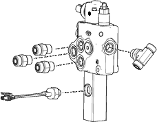
Install the 3 straight fittings to the 3 side ports (Figure 13).
Tighten the straight fittings to 78.6 to 97.6 N-m (58 to 72 ft-lb).
Hand tighten the tee fitting, then orient the ends at a 45-degree angle as shown in Figure 13.
While maintaining proper orientation, torque the tee fitting to 78.6 to 97.6 N-m (58 to 72 ft-lb).
Remove the plug from the side of the new auxiliary valve and thread the ball switch into the port (Figure 13).
Tighten the ball switch to 24.4 to 29.8 N-m (18 to 22 ft-lb).
Parts needed for this procedure:
| Auxiliary valve | 1 |
Align the auxiliary valve with the 3 holes on the mounting bracket.
Secure the auxiliary valve to the bracket with the front 3 bolts and nuts (Figure 14).
Important: Ensure that the bolts are oriented as shown in Figure 14.
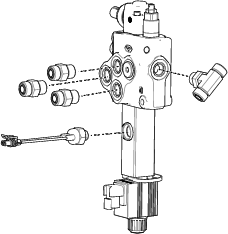
Connect the long and short hoses into the tee fitting on the front of the auxiliary valve (Figure 15).
Note: Ensure that the long hose (from the gear pump) is routed through the rubber baffle before installing it to the tee fitting.
Tighten the hoses on the tee fitting to 50.2 to 63.7 N-m (37 to 47 ft-lb).
Attach the elbow fitting to the port on the back of the auxiliary valve (Figure 16).
Tighten the elbow fitting to 78.6 to 97.6 N-m (58 to 72 ft-lb).
Remove the plug from the return hose, and attach it to the elbow fitting with the hose clamp (Figure 16).
Attach the 3 pressure hoses to the straight fittings on the side of the auxiliary valve according to the marks made in 3 of Removing the Existing Auxiliary Valve .
Note: If you removed the clamp plate in 4 of Removing the Existing Auxiliary Valve , install it now.
Tighten the 3 pressure hoses to 50.2 to 63.7 N-m (37 to 47 ft-lb).
Attach the ball switch plug into the wire harness connector.
Attach the extension plug into the socket for the foot-switch.
Plug the extension wire into the main wire harness for the foot switch.
Install the auxiliary handle using the parts you removed in Removing the Auxiliary Handle.
 |
Check and tighten all fittings and hydraulic connections.
Check the coolant and hydraulic fluid levels and replenish it as required; refer to the Operator’s Manual for your machine.
Start the machine and allow the hydraulic system to pressurize.
Stop the engine and check the hydraulic tubes, hoses, and fittings for leaks.
Note: Repair all leaks before operating the machine.
Install the 3 bolts to secure the heat cover (Figure 17).
Install the 2 bolts and 2 washers to secure the rubber baffle to the machine (Figure 19).
Lift up on the tab securing the prop-rod and lower the hood.
Tighten the hood-locking screw to secure the latch.
Lower the operator’s pad.
Test the auxiliary valve function in both the forward and rearward directions.