


Maintenance
Important: Refer to your engine owner’s manual for additional maintenance procedures.
Note: Download a free copy of the electrical or hydraulic schematic by visiting www.Toro.com and searching for your machine from the Manuals link on the home page.
Note: Determine the left and right sides of the machine from the normal operating position.
Recommended Maintenance Schedule(s)
| Maintenance Service Interval | Maintenance Procedure |
|---|---|
| After the first operating hour |
|
| After the first 10 operating hours |
|
| After the first 50 operating hours |
|
| After the first 200 operating hours |
|
| Before each use or daily |
|
| Every 50 hours |
|
| Every 100 hours |
|
| Every 200 hours |
|
| Every 250 hours |
|
| Every 400 hours |
|
| Every 800 hours |
|
| Before storage |
|
| Yearly |
|
Service Interval Chart
Pre-Maintenance Procedures
Pre-Maintenance Safety
-
Before adjusting, cleaning, repairing, or leaving the machine, do the following:
-
Park the machine on a level surface.
-
Move the throttle switch to the low-idle position.
-
Disengage the cutting units.
-
Lower the cutting units.
-
Ensure that the traction is in neutral.
-
Engage the parking brake.
-
Shut off the engine and remove the key.
-
Wait for all moving parts to stop.
-
Allow machine components to cool before performing maintenance.
-
-
If the cutting units are in the transport position, use the positive mechanical lock (if available) before you leave the machine unattended.
-
If possible, do not perform maintenance while the engine is running. Keep away from moving parts.
-
Use jack stands to support the machine or components when required.
-
Carefully release pressure from components with stored energy.
Preparing the Machine for Maintenance
-
Ensure that the PTO is disengaged.
-
Park the machine on a level surface.
-
Engage the parking brake.
-
Lower the cutting unit(s) if necessary.
-
Shut off the engine and wait for all moving parts to stop.
-
Turn the ignition key to the STOP position and remove it.
-
Allow machine components to cool before performing maintenance.
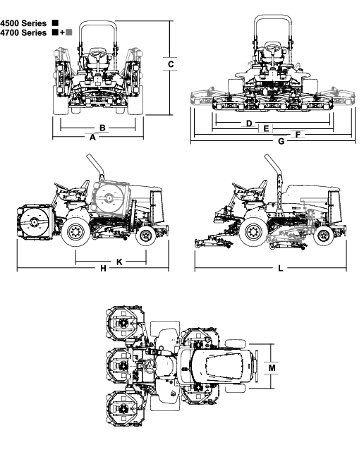
Lifting the Machine
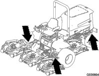
Use the following as points to lift the machine:
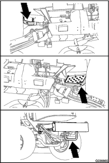
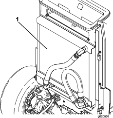
Front of the machine—at the frame of the machine, forward of the wheel-drive motors (Figure 29)
Important: Do not support the machine at the wheel-drive motors. Keep the lifting equipment clear of hydraulic tubing and hoses.
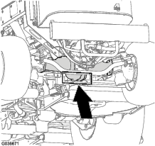
Rear of the machine—at the center of the axle (Figure 30)
Locate the jackstands of the specified capacity at both sides of the gear case and under the axle.
Important: Do not support the machine at the tie rod.
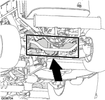
Opening the Hood
Accessing the Hydraulic Lift Compartment
Lubrication
Greasing the Bearings and Bushings
Grease specification: No. 2 lithium grease
The grease fitting locations and quantities are as follows:
-
Brake-shaft pivot bearings (5) as shown in Figure 33
-
Rear-axle-pivot bushings (2) as shown in Figure 34)
-
Steering-cylinder ball joints (2) as shown in Figure 35
-
Tie-rod ball joints (2) as shown in Figure 35
-
Kingpin bushings (2) as shown in Figure 35
Important: The top fitting on the kingpin should only be lubricated annually (2 pumps).
-
Lift-arm bushings (1 per deck) as shown in Figure 36
-
Lift-cylinder bushings (2 per deck) as shown in Figure 36
-
Cutting-unit spindle-shaft bearings (2 per mower deck) as shown in Figure 37
Note: You can use either fitting, whichever is more accessible. Pump grease into the fitting until a small amount appears at the bottom of the spindle housing (under the deck).
-
Cutting-unit carrier-arm bushings (1 per mower deck) as shown in Figure 37
-
Rear roller bearings (2 per mower deck) as shown in Figure 38
Important: Make sure that the grease groove in each roller mount aligns with the grease hole in each end of the roller shaft. To help align the groove and the hole, there is also an alignment mark on 1 end of the roller shaft.
Engine Maintenance
Engine Safety
-
Shut off the engine before checking the oil or adding oil to the crankcase.
-
Do not change the governor speed or overspeed the engine.
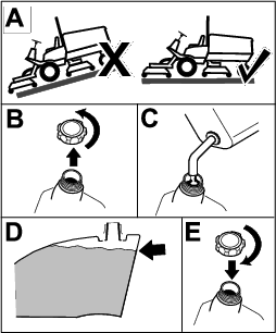
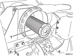
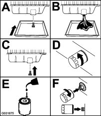
Servicing the Air Cleaner
Check the air-cleaner body for damage which could cause an air leak. Replace it if it is damaged. Check the whole intake system for leaks, damage, or loose hose clamps.
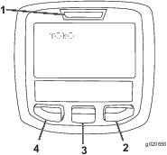
Service the air-cleaner filter only when the service indicator (Figure 39) requires it. Changing the air filter before it is necessary only increases the chance of dirt entering the engine when you remove the filter.
Important: Be sure that the cover is seated correctly and seals with the air-cleaner body.
-
Replace the air cleaner (Figure 40).
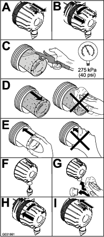
Note: Do not clean a used element because cleaning it can damage the filter media.
Important: Never attempt to clean the safety filter (Figure 41). Replace the safety filter after every 3 primary filter services.
-
Reset the indicator (Figure 39) if it shows red.
Servicing the Engine Oil
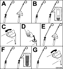
Checking the Engine-Oil Level
Crankcase oil capacity: approximately 5.7 L (6 US qt) with the filter.
Oil specification: API classification CH-4, CI-4, or higher.
Oil viscosity specification:
-
Preferred oil: SAE 15W-40 (above -18°C [0°F])
-
Alternate oil: SAE 10W-30 or 5W-30 (all temperatures)
Note: The engine is shipped with oil in the crankcase; however, the oil level must be checked before and after the engine is first started.Use only high-quality engine oil.
Note: Toro Premium Engine oil is available from your distributor in either 15W-40 or 10W-30 viscosity. See the Parts Catalog for part numbers.
Note: Check the engine oil level is before the engine is run for the day and the engine is cool . If the engine has already been run: shut off the engine, wait least 10 minutes to allow the oil to drain back down to the sump, and check the engine oil level. If the oil level is at or below the ADD mark on the dipstick, add oil to bring the oil level to the FULL mark. Do not overfill. If the oil level is between the FULL and ADD marks, no oil addition is required.
-
Park the machine on a level surface.
-
Check the engine-oil level (Figure 42).
Note: When using different oil, drain all old oil from the crankcase before adding new oil.
Changing the Engine Oil and Filter
-
Start the engine and let it run 5 minutes to allow the oil to warm up.
-
Park the machine on a level surface, engage the parking brake, shut off the engine, and remove the key.
-
Replace the engine oil and filter (Figure 43).
-
Add oil to the crankcase.
Fuel System Maintenance
Danger
Under certain conditions, diesel fuel and fuel vapors are highly flammable and explosive. A fire or explosion from fuel can burn you and others and can cause property damage.
-
Use a funnel to fill the fuel tank outdoors, in an open area, when the engine is off and is cold. Wipe up any fuel that spills.
-
Do not fill the fuel tank completely full. Add fuel to the fuel tank until the level is 6 to 13 mm (1/4 to 1/2 inch) below the bottom of the filler neck. This empty space in the tank allows the fuel to expand.
-
Never smoke when handling fuel, and stay away from an open flame or where fuel fumes may be ignited by a spark.
-
Store fuel in a clean, safety-approved container and keep the cap in place.
Draining the Fuel Tank
Drain and clean the tank also if the fuel system becomes contaminated or if you are storing the machine for an extended period of time. Use clean fuel to flush out the tank.
Close sectionInspecting the Fuel Lines and Connections
Inspect the fuel lines and connections for deterioration, damage, or loose connections.
Close sectionServicing the Water Separator
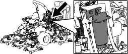
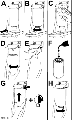
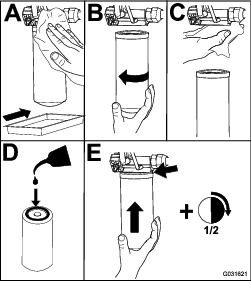
Servicing the Fuel Filter
-
Clean the area around the fuel-filter head (Figure 45).
-
Remove the filter and clean the filter head mounting surface (Figure 45).
-
Lubricate the filter gasket with clean lubricating engine oil; refer to the engine owner's manual for additional information.
-
Install the dry filter canister, by hand, until the gasket contacts the filter head, then rotate it an additional 1/2 turn.
-
Start the engine and check for fuel leaks around the filter head.
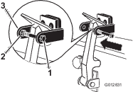
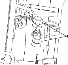
Cleaning the Fuel-Pickup Tube Screen
The fuel-pickup tube, located inside the fuel tank, is equipped with a screen to help prevent debris from entering the fuel system. Remove the fuel-pickup tube and clean the screen as required.
-
Remove the hose clamp that secures the fuel supply hose to the fitting of the fuel-pickup tube (Figure 46).
-
Separate the hose from the fitting (Figure 46).
-
Lift the fuel-pickup tube from the fuel tank (Figure 46).
Note: Lift the tube straight from the busing in the tank.
-
Clean any debris from the screen at the end of the fuel-pickup tube (Figure 46).
-
Insert the fuel-pickup tube through the rubber bushing and into the tank (Figure 46).
Note: Ensure that the fuel-pickup tube is fully seated into the rubber bushing.
-
Install the supply hose onto the fitting of the fuel-pickup tube, and secure the hose with the hose clamp that you removed in step 1.
Priming the Fuel System
Prime the fuel system before starting the engine for the first time, after running out of fuel, or after fuel system maintenance (e.g. draining the filter/water separator, replacing a fuel hose). To prime the fuel system, make sure that the fuel tank has fuel in it. Then, turn the ignition key to the ON position for 10 to 15 seconds which allows the fuel pump to prime the fuel system.
Important: Do not use the engine starter motor to crank the engine in order to prime the fuel system.
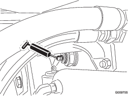
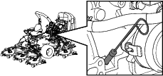
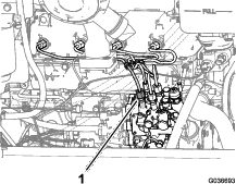
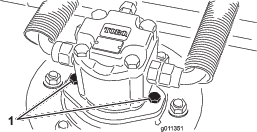
Close sectionBleeding Air from the Injectors
Note: Use this procedure only if the fuel system has been purged of air through normal priming procedures and the engine does not start.
-
Loosen the tube nut for the cylinder #1 fuel-injector at the injection pump (Figure 47).
-
Move the throttle to the FAST position.
-
Turn the key in the ignition switch to the START position and watch the fuel flow around the connector.
-
Turn the key to the OFF position when you observe solid flow.
-
Tighten the pipe connector securely.
-
Clean all residual fuel from the engine.
-
Repeat the procedure for the remaining fuel-injector tubes.
Electrical System Maintenance
Electrical System Safety
-
Disconnect the battery before repairing the machine. Disconnect the negative terminal first and the positive last. Connect the positive terminal first and the negative last.
-
Charge the battery in an open, well-ventilated area, away from sparks and flames. Unplug the charger before connecting or disconnecting the battery. Wear protective clothing and use insulated tools.
Checking the Battery Condition
Important: Before welding on the machine, disconnect the negative cable from the battery to prevent damage to the electrical system. Also, you must disconnect the engine, InfoCenter, and machine controllers before welding on the machine.
Note: Keep the terminals and the entire battery case clean, because a dirty battery discharges slowly. To clean the battery, wash the entire case with a solution of baking soda and water. Rinse with clear water. Coat the battery posts and cable connectors with Grafo 112X (skin-over) grease (Toro Part No. 505-47) or petroleum jelly to prevent corrosion.
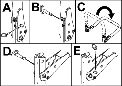
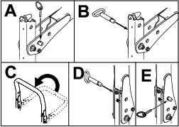
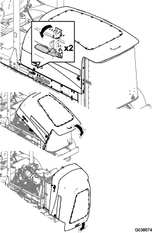
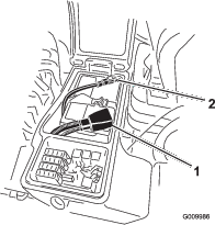
Close sectionCharging and Connecting the Battery
-
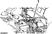
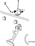
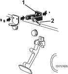
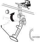
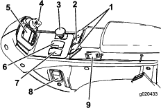
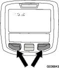
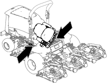
Unlatch and raise the operator's console panel (Figure 48).
Danger
Battery electrolyte contains sulfuric acid, which is fatal if consumed and causes severe burns.
-
Do not drink electrolyte and avoid contact with skin, eyes, or clothing. Wear safety glasses to shield your eyes and rubber gloves to protect your hands.
-
Fill the battery where clean water is always available for flushing the skin.
-
-
Remove the rubber boot from the positive terminal and inspect the battery.
-
Remove the negative cable (black) from the negative (-) terminal and the positive cable (red) from the positive (+) terminal of the battery (Figure 49).
Warning
Incorrect battery cable routing could damage the machine and cables, causing sparks. Sparks can cause the battery gasses to explode, resulting in personal injury.
-
Always disconnect the negative (black) battery cable before disconnecting the positive (red) cable.
-
Always connect the positive (red) battery cable before connecting the negative (black) cable.
Warning
Battery terminals or metal tools could short against metal components, causing sparks. Sparks can cause the battery gasses to explode, resulting in personal injury.
-
When removing or installing the battery, do not allow the battery terminals to touch any metal parts of the machine.
-
Do not allow metal tools to short between the battery terminals and metal parts of the machine.
-
-
Connect a 3 to 4 A battery charger to the battery posts. Charge the battery at a rate of 3 to 4 A for 4 to 8 hours.
Warning
Charging the battery produces gasses that can explode.
Never smoke near the battery and keep sparks and flames away from battery.
-
When the battery is charged, disconnect the charger from the power outlet and battery posts.
-
Install the positive cable (red) to the positive (+) terminal and the negative cable (black) to the negative (-) terminal of the battery (Figure 49).
-
Secure the cables to the posts with bolts and nuts.
Note: Make sure that the positive (+) terminal is all the way on the post and the cable is positioned snug to the battery. The cable must not contact the battery cover.
-
Coat both battery connections with Grafo 112X (skin-over) grease, Part No. 505-47, petroleum jelly, or light grease to prevent corrosion.
-
Slide the rubber boot over the positive terminal.
-
Close the console panel and secure the latch.
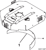
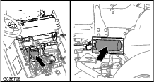
Locating the Fuses
The fuse block for the machine is located in the right storage box

-
Loosen the latch for the cover of the right storage box and raise the cover (Figure 51) to expose the fuse block (Figure 52).
-
Replace the open fuse(s) as needed (Figure 52).
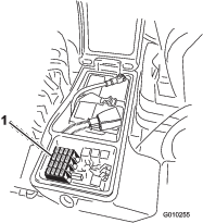
-
Close the cover of the right storage box and secure the cover with the latch (Figure 51).
Drive System Maintenance
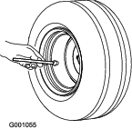
Checking for End-Play in the Planetary Drives
There should be no end-play in the planetary drives/drive wheels (i.e., the wheels should not move when you pull or push them in a direction parallel to the axle).
-
Park the machine on a level surface, engage the parking brake, lower the mower decks, shut off the engine, and remove the key.
-
Chock the rear wheels and raise the front of machine, supporting the front axle/frame on jack stands.
Danger
A machine on a jack may be unstable and slip off the jack, injuring anyone beneath it.
-
Do not start the engine while the machine is on a jack.
-
Always remove the key from the switch before getting off the machine.
-
Block the tires when you are raising the machine with a jack.
-
Support the machine with jack stands.
-
-
Grasp 1 of the front drive wheels and push/pull it toward and away from the machine, noting any movement.

-
Repeat step 3 for the other drive wheel.
-
If either wheel moves, contact your Toro Distributor to have the planetary drive rebuilt.
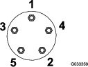
Checking the Planetary-Gear-Drive Oil
Use high quality SAE 85W-140 gear lube as a replacement.
-
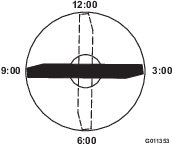
With machine on level surface, position the wheel so that 1 check plug is at the 12 o'clock position and the other is at 3 o'clock position (Figure 54).
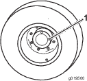
-
Remove the plug at the 3 o’clock position (Figure 54).
The oil level should be at the bottom of the check-plug hole.
-
If the oil level is low, remove the plug at the 12 o’clock position and add oil until it begins to flow out of the hole at the 3 o’clock position.
-
Install both plugs.
-
Repeat steps 1 through 4 on the opposite planetary gear assembly.
Changing the Planetary-Gear-Drive Oil
Use a high-quality, SAE 85W-140 gear lube.
-
With the machine on a level surface, position a wheel so that a check plug is at the lowest (6 o'clock) position (Figure 55).
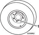
-
Place a drain pan under the planetary hub, remove the plug, and allow the oil to drain.
-
Place a drain pan under the brake housing, remove the drain plug, and allow the oil to drain (Figure 56).
-
When all of the oil has drained from both locations, install the plug in the brake housing.
-
Rotate the wheel until the open plug hole in the planetary is at the 12 o'clock position.
-
Through the open hole, slowly fill the planetary with 0.65 L (22 fl oz) of high quality SAE 85W-140 wt gear lube.
Important: If the planetary fills before the 0.65 L (22 fl oz) of oil is added, wait 1 hour or install the plug and move the machine approximately ten feet to distribute the oil through the brake system. Then, remove the plug and add the remaining oil.
-
Install the plug.
-
Repeat the procedure on the opposite planetary/brake assembly.
Checking the Rear Axle and Gearbox for Leaks
Checking the Rear-Axle Lubricant
The rear axle is filled with SAE 85W-140 gear lube. The capacity is 2.4 L (80 fl oz). Visually inspect for leaks daily.
-
Position the machine on a level surface.
-
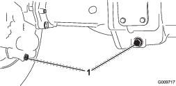
Remove a check plug from 1 end of the axle and ensure that the lubricant is up to the bottom of the hole (Figure 58).
Note: If the level is low, remove the fill plug and add enough lubricant to bring the level up to the bottom of the check-plug holes.
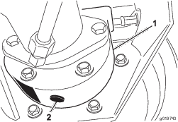
Changing the Rear-Axle Lubricant
Lubricant specification: high-quality SAE 85W-140 gear lubricant
Axle capacity: 2.4 L (80 fl oz)
-
Position the machine on a level surface.
-
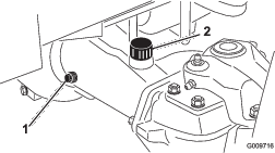
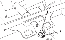
Clean the area around the 3 drain plugs—1 on each end and 1 in the center (Figure 59).
-
Remove the oil-level check plugs and the main-axle-vent cap to ease draining the gear lubricant.
-
Remove the drain plugs and allow the gear lubricant to drain into the pans.
-
Install the plugs.
-
Remove a check plug and fill the axle with approximately 2.4 L (80 fl oz) of 85W-140 gear lube or until the lubricant is up to the bottom of the hole.
-
Install the check plug.
Checking the Rear-Axle-Gearbox Lubricant
The gear box is filled with SAE 85W-140 gear lube. The capacity is 0.5 L (16 fl oz). Visually inspect for leaks daily.
-
Position the machine on a level surface.
-
Remove the check/fill plug from the left side of the gear box and ensure that lubricant is up to the bottom of the hole (Figure 60).
Note: If the level is low, add enough lubricant to bring the level up to the bottom of the hole.
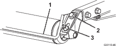
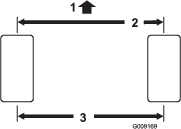
Checking the Rear Wheel Toe-In
-
Measure the center-to-center distance (at axle height) at the front and rear of the steering tires (Figure 61).
Note: The front measurement must be 3 mm (1/8 inch) less than the rear measurement.
-
To adjust, remove the cotter pin and nut from either tie rod ball joint (Figure 62). Remove the tie-rod ball joint from the axle-case support.
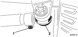
-
Loosen the clamps at both ends of the tie rods (Figure 62).
-
Rotate the detached ball joint inward or outward 1 complete revolution and tighten the clamp at the loose end of the tie rod.
-
Rotate the entire tie-rod assembly the same direction (inward or outward) 1 complete revolution and tighten the clamp at the connected end of the tie rod.
-
Install the ball joint in the axle-case support, tighten the nut finger-tight, and measure the toe-in.
-
Repeat procedure if necessary.
-
Tighten the nut and install a new cotter pin when the adjustment is correct.
Cooling System Maintenance
Cooling System Safety
-
Swallowing engine coolant can cause poisoning; keep out of reach from children and pets.
-
Discharge of hot, pressurized coolant or touching a hot radiator and surrounding parts can cause severe burns.
-
Always allow the engine to cool at least 15 minutes before removing the radiator cap.
-
Use a rag when opening the radiator cap, and open the cap slowly to allow steam to escape.
-
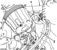
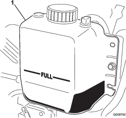
Checking the Cooling System
Coolant specification: 50/50 mixture of water and ethylene glycol antifreeze
Cooling system capacity: 8.5 L (9 US qt).
-
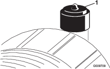
Carefully remove the radiator cap.
Caution
If the engine has been running, the pressurized, hot coolant can escape and cause burns.
-
Do not open the radiator cap when the engine is running.
-
Use a rag when opening the radiator cap, and open the cap slowly to allow steam to escape.
-
-
Check the coolant level in the radiator. The radiator should be filled to the top of the filler neck and the expansion tank filled to the FULL mark (Figure 63).
-
If the coolant is low, add a 50/50 mixture of water and ethylene glycol anti freeze. Do not use water only or alcohol/methanol base coolants.
-
Install the radiator cap and expansion-tank cap.
Cleaning the Cooling System
Clean them more frequently in dirty conditions.
This machine is equipped with a hydraulically driven fan drive system that automatically (or manually) reverses to reduce oil cooler/radiator and screen debris buildup. While this feature can help reduce the time required to clean oil cooler/radiator, it does not eliminate the need for routine cleaning. Periodic cleaning and inspection of the radiator/cooler is still required.
-
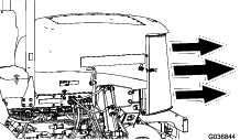
Unlatch and swing open the rear screen (Figure 64).
Note: To remove the screen, lift it off the hinge pins.
-
Clean the screen thoroughly of all debris.
-
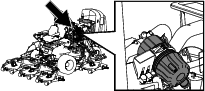
Thoroughly clean both sides of the oil cooler and the radiator with compressed air (Figure 65).
Note: Start from the front and blow the debris out toward the back. Then clean from the back side and blow toward the front. Repeat procedure several times until you remove all chaff and debris.
Important: Cleaning the oil cooler/radiator with water promotes premature corrosion damage to components and compacts debris.
-
Close the rear screen and secure it with the latch.
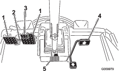
Brake Maintenance
Adjusting the Service Brakes
Adjust the service brakes when there is more than 25 mm (1 inch) of free travel of the brake pedal, or when the brakes do not work effectively. Free travel is the distance the brake pedal moves before you feel braking resistance.
-
Release the locking latch from the brake pedals so that both pedals work independently of each other.
-
To reduce free travel of the brake pedals, tighten the brakes as follows:
-
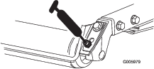
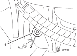
Loosen the front nut on the threaded end of the brake cable (Figure 66).
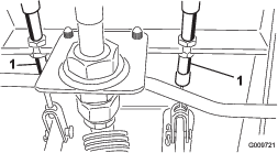
-
Tighten the rear nut to move the cable rearward until the brake pedals have 13 to 25 mm (1/2 to 1 inch) of free travel.
-
Tighten the front nuts after the brakes are adjusted correctly.
-
Belt Maintenance
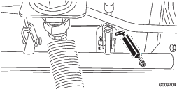
Servicing the Alternator Belt
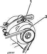
Proper tension of the belt allows 10 mm (3/8 inch) of deflection when a force of 4.5 kg (10 lb) is applied on the belt midway between the pulleys.
If the deflection is not 10 mm (3/8 inch), loosen the alternator-mounting bolts (Figure 67).
Note: Increase or decrease the alternator-belt tension and tighten the bolts. Check the deflection of the belt again to ensure that the tension is correct.
Hydraulic System Maintenance
Hydraulic System Safety
-
Ensure that all hydraulic-fluid hoses and lines are in good condition and all hydraulic connections and fittings are tight before applying pressure to the hydraulic system.
-
Keep your body and hands away from pinhole leaks or nozzles that eject high-pressure hydraulic fluid.
-
Use cardboard or paper to find hydraulic leaks.
-
Safely relieve all pressure in the hydraulic system before performing any work on the hydraulic system.
-
Seek immediate medical attention if fluid is injected into skin. Injected fluid must be surgically removed within a few hours by a doctor.
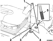
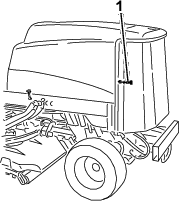
Checking the Hydraulic-Fluid Level
The reservoir is filled at the factory with approximately 28.4 L (7.50 US gallons) of high-quality hydraulic fluid. Check the level of the hydraulic fluid before the engine is first started and daily thereafter. The recommended replacement fluid is as follows:
Toro Premium All Season Hydraulic Fluid (Available in 19 L (5 US gallons) pails or 208 L (55 US gallons) drums. See the Parts Catalog or your Toro Distributor for part numbers).
Alternative fluids: If the Toro fluid is not available, other conventional, petroleum-based fluids may be used, provided they meet all of the following material properties and industry specifications. Check with your oil supplier to see whether the oil meets these specifications.
Note: Toro does not assume responsibility for damage caused by improper substitutions, so use only products from reputable manufacturers who will stand behind their recommendation.
| Material Properties: | |||
| Viscosity, ASTM D445 | cSt @ 40°C (104°F) 44 to 48cSt @ 100°C (212°F) 7.9 to 9.1 | ||
| Viscosity Index ASTM D2270 | 140 to 160 | ||
| Pour Point, ASTM D97 | -37°C to -45°C (-34°F to -49°F) | ||
| Industry Specifications: | Vickers I-286-S (Quality Level), Vickers M-2950-S (Quality Level), Denison HF-0 | ||
Important: The ISO VG 46 Multigrade fluid has been found to offer optimal performance in a wide range of temperature conditions. For operation in consistently high ambient temperatures, 65°F (18°C) to 120°F (49°C), ISO VG 68 hydraulic fluid may offer improved performance.
Premium Biodegradable Hydraulic Fluid-Mobil EAL EnviroSyn 46H
Important: Mobil EAL EnviroSyn 46H is the only synthetic biodegradable fluid approved by Toro. This fluid is compatible with the elastomers used in Toro hydraulic systems and is suitable for a wide-range of temperature conditions. This fluid is compatible with conventional mineral oils, but for maximum biodegradability and performance the hydraulic system should be thoroughly flushed of conventional fluid. The fluid is available in 19 L (5 US gallon) containers or 208 L (55 US gallon) drums from your Mobil Distributor.
Important: Many hydraulic fluids are almost colorless, making it difficult to spot leaks. A red dye additive for the hydraulic system fluid is available in 20 ml (2/3 oz) bottles. 1 bottle is sufficient for 15 to 22 L (4 to 6 US gallons) of hydraulic fluid. Order part no. 44-2500 from your Toro Distributor.
-
Park the machine on a level surface, engage the parking brake, lower the mower decks, shut off the engine, and remove the key.
-
Check the hydraulic-fluid level (Figure 68).

Changing the Hydraulic Fluid
If the fluid becomes contaminated, contact your Toro Distributor because the system must be flushed. Contaminated fluid looks milky or black when compared to clean oil.
-
Park the machine on a level surface, engage the parking brake, lower the mower decks, shut off the engine, and remove the key.
-
Raise the hood.
-
Disconnect the case return line from the bottom of the reservoir and let the hydraulic fluid flow into a large drain pan.
-
Install the hose when the hydraulic fluid stops draining.
-
Fill the reservoir with hydraulic fluid; refer to Checking the Hydraulic-Fluid Level.
Important: Use only the hydraulic fluids specified. Other fluids could cause system damage.
-
Install the reservoir cap.
-
Turn the key in the key switch to the ON position to start the engine. Use all the hydraulic controls to distribute hydraulic fluid throughout the system, and check for leaks.
-
Turn the key in the key switch to the OFF position.
-
Check the fluid level and add enough to raise level the level to the FULL mark on the dipstick. Do not overfill.
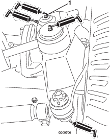
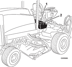
Replacing the Hydraulic Filters
Use Toro replacement filters Part No. 94-2621 for the rear (mower decks) of the machine and Part No. 75-1310 for the front (charge) of the machine.
Important: Use of any other filter may void the warranty on some components.
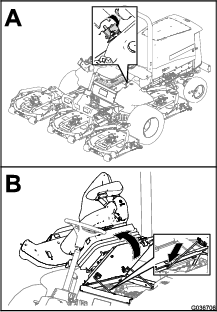
-
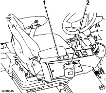
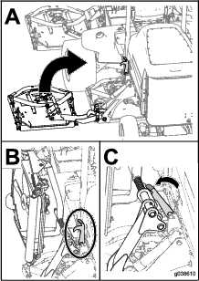
Tilt the operators seat to access the mower pressure filter; refer to Accessing the Hydraulic Lift Compartment
-
Replace the charge hydraulic filter at the hydraulic lift compartment as shown in Figure 70.
-
Lower and secure the operator’s seat.
-
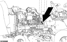
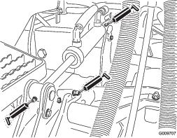
Replace the return filter at the right side of the machine (Figure 70).
-
Start the engine and let it run for about 2 minutes to purge air from the system. Shut off the engine and check for leaks.
Checking the Hydraulic Lines and Hoses
Inspect the hydraulic lines and hoses daily for leaks, kinked lines, loose mounting supports, wear, loose fittings, weather deterioration, and chemical deterioration. Make all necessary repairs before operating the machine.
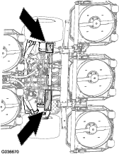
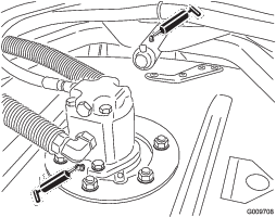
Close sectionRemoving the Mower Decks
-
Park the machine on a level surface, engage the parking brake, lower the mower decks, shut off the engine, and remove the key.
-
Disconnect and remove the hydraulic motor from the deck (Figure 71). Cover the top of the spindle to prevent contamination.
-
Remove the lynch pin (for Groundsmaster 4500 machines) or retaining nut (for Groundsmaster 4700 machines) securing the deck-carrier frame to the lift-arm pivot pin (Figure 72).
-
Roll the cutting deck away from the machine.
Installing the Mower Decks
-
Move the mower deck into position in front of the machine.
-
Slide the deck carrier frame onto the lift-arm-pivot pin (Figure 72). Secure the deck to the pin with the lynch pin (for Groundsmaster 4500 machines) or retaining nut (for Groundsmaster 4700 machines).
-
Install the hydraulic motor to the deck (Figure 71). Make sure that the O-ring is in position and not damaged.
-
Grease the spindle.
Servicing the Front Roller
Inspect the front roller for wear, excess wobble, or binding. Service or replace the roller or components if any of these conditions exist.
Disassembling the Front Roller
-
Remove the roller-mounting bolt (Figure 73).
-
Insert a punch through the end of the roller housing and drive the opposite bearing out by alternating taps to the opposite side of inner bearing race. There should be a 1.5 mm (0.060 inch) lip of inner race exposed.

-
Push the second bearing out in press.
-
Inspect the roller housing, bearings, and bearing spacer for damage (Figure 73). Replace damaged components and assemble.
Assembling the Front Roller
-
Press the first bearing into the roller housing (Figure 73). Press on the outer race only or equally on the inner and outer race.
-
Insert the spacer (Figure 73).
-
Press the second bearing into the roller housing (Figure 73). Pressing equally on the inner and outer race until the inner race comes in contact with the spacer.
-
Install the roller assembly into the deck frame.
-
Verify that there is no more than a 1.5 mm (0.060 inch) gap between roller assembly and the roller mount brackets of the deck frame. If there is a gap over 1.5 mm (0.060 inch), install enough 5/8-inch diameter washers to take up the slop.
Important: Securing the roller assembly with a gap larger than 1.5 mm (0.060 inch) creates a side load on the bearing and can lead to premature bearing failure
-
Torque the mounting bolt to 108 N∙m (80 ft-lb).
Blade Safety
A worn or damaged blade can break, and a piece of the blade could be thrown toward you or bystanders, resulting in serious personal injury or death.
-
Inspect the blade periodically for wear or damage.
-
Use care when checking the blades. Wrap the blades or wear gloves, and use caution when servicing the blades. Only replace or sharpen the blades; never straighten or weld them.
-
On multi-bladed machines, take care as rotating 1 blade can cause other blades to rotate.
Servicing the Blade Plane
The mower deck comes from the factory preset at 5 cm (2 inches) height of cut and blade rake of 7.9 mm (0.310 inch). The left and right heights are also preset to within 0.7 mm (0.030 inch) of the other.
The mower deck is designed to withstand blade impacts without deformation of the chamber. If a solid object is struck, inspect the blade for damage and the blade plane for accuracy.
Inspecting the Blade Plane
-
Remove the hydraulic motor from the mower deck and remove the mower deck from the machine.
-
Use a hoist (or minimum of 2 people) and place the mower deck on a flat table
-
Mark 1 end of the blade with a paint pen or marker. Use this end of the blade to check all heights.
-
Position the cutting edge of the marked end of the blade at 12 o’clock (straight ahead in the direction of mowing) (Figure 74) and measure height from table to cutting edge of blade.
-
Rotate the marked end of the blade to the 3 and 9 o’clock positions (Figure 74) and measure the heights.
-
Compare the 12 o’clock measured height to the height-of-cut setting. It should be within 0.7 mm (0.030 inch). The 3 and 9 o’clock heights should be 1.6 to 6.0 mm (0.060 to 0.240 inch) higher than the 12 o’clock setting and within 2.2 mm (0.090 inch) of each other.
If any of these measurements are not within specification, proceed to Adjusting the Blade Plane.
Close sectionAdjusting the Blade Plane
Start with the front adjustment (change 1 bracket at a time).
-
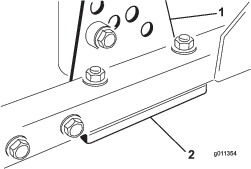
Remove the height-of-cut bracket, (front, left, or right) from the deck frame (Figure 75).
-
Adjust 1.5 mm (0.060 inch) shims and/or 0.7 mm (0.030 inch) shims between the deck frame and bracket to achieve the desired height setting (Figure 75).
-
Install the height-of-cut bracket to the deck frame with the remaining shims assembled below the height-of-cut bracket.
-
Secure the socket-head bolt/spacer and flange nut.
Note: Socket-head bolt/spacer are held together with thread-locking adhesive to prevent the spacer from falling inside the deck frame.
-
Verify the 12 o’clock height and adjust if needed.
-
Determine if only 1 or both (right and left) height-of-cut brackets need to be adjusted.
Note: If the 3 or 9 o’clock side is 1.6 to 6.0 mm (0.060 to 0.240 inch) higher than the new front height then no adjustment is needed for that side. Adjust the other side to within 2.2 mm (0.090 inch) of the correct side.
-
Adjust the right and/or left height-of-cut brackets by repeating steps 1 through 4.
-
Secure the carriage bolts and flange nuts.
-
Verify the 12, 3, and 9 o’clock heights.
Removing and Installing the Mower Blade(s)
Replace the blade if it hits a solid object, is out of balance, or if it is bent. Always use genuine Toro replacement blades to ensure safety and optimum performance.
-
Park the machine on a level surface, raise the mower deck to the highest position, engage the parking brake, shut off the engine, and remove the key.
Note: Block the mower deck to prevent it from accidentally falling.
-
Grasp the end of the blade using a rag or thickly-padded glove.
-
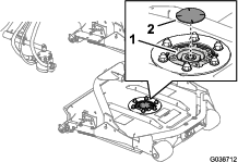
Remove the blade bolt, anti-scalp cup, and blade from the spindle shaft (Figure 76).

-
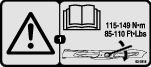
Install the blade, anti-scalp cup, and blade bolt and tighten the blade bolt to 115 to 149 N∙m (85 to 110 ft-lb).
Important: The curved part of the blade must be pointing toward the inside of the mower deck to ensure proper cutting.
Note: After striking a foreign object, torque all of the spindle-pulley nuts to 115 to 149 N∙m (85 to 110 ft-lb).
Inspecting and Sharpening the Mower Blade(s)
Two areas must be considered when checking and servicing the mower blade—the sail and the cutting edge. Both cutting edges and the sail, which is the turned-up portion opposite of the cutting edge, contribute to a good quality of cut. The sail is important because it lifts the grass up straight, thereby producing an even cut. However, the sail gradually wears down during operation. As the sail wears down, the quality of cut degrades, although the cutting edges are sharp. The cutting edge of the blade must be sharp so that the grass is cut rather than torn. A dull cutting edge is evident when the tips of the grass appear brown and shredded. Sharpen the cutting edges to correct this condition.
-
Park the machine on a level surface, raise the mower decks, engage the parking brake, put the traction pedal in NEUTRAL, put the PTO lever in the OFF position, shut off the engine, and remove the key.
-
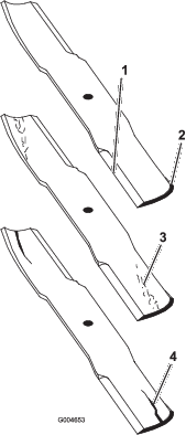
Examine the cutting ends of the blade carefully, especially where the flat and curved parts of the blade meet (Figure 77).
Note: Because sand and abrasive material can wear away the metal that connects the flat and curved parts of the blade, check the blade before using the mower. If wear is noticed (Figure 77), replace the blade.
-
Examine the cutting edges of all of the blades and sharpen the cutting edges if they are dull or nicked (Figure 77).
Note: Sharpen only the top of the cutting edge and maintain the original cutting angle to ensure sharpness (Figure 78). The blade remains balanced if the same amount of metal is removed from both cutting edges.
Note: Remove the blades and sharpen them on a grinder. After sharpening the cutting edges, install the blade with the anti-scalp cup and blade bolt; refer to Removing and Installing the Mower Blade(s).