CALIFORNIA
Proposition 65 Warning
 |
Safety decals and instructions are easily visible to the operator and are located near any area of potential danger. Replace any decal that is damaged or missing. |

Park the machine on a level surface.
Disengage the blade-control switch.
Move the motion-control levers outward to the NEUTRAL-LOCK position.
Engage the parking brake.
Shut off the engine and remove the key.
Parts needed for this procedure:
| LED light | 1 |
| Front light bracket | 1 |
| Thread-forming screw (5/16 x 3/4 inch)—standard platform only | 2 |
| Hex-head bolt (5/16 x 3/4 inch) | 1 |
| Flange nut (5/16 inch) | 1 |
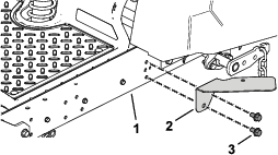
If you have a machine with a MyRide ™ platform, remove the existing 2 thread-forming screws (5/16 x 3/4) securing the bumper brackets (Figure 1).
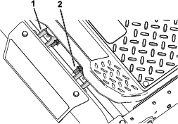
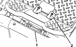
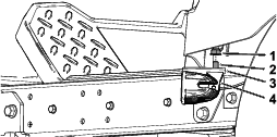
If you have a machine with a MyRide ™ platform, install the front light bracket using the previously removed 2 thread-forming screws (5/16 x 3/4) as shown in Figure 2.
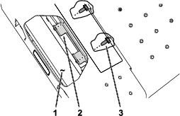
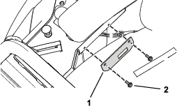
If you have a machine with a standard platform, install the front light bracket to the front axle tube using the 2 thread-forming screws (5/16 x 3/4) provided with the kit (Figure 3).
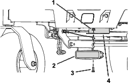
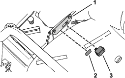
Secure the LED light to the front light bracket using a hex-head bolt (5/16 x 3/4 inch) and flange nut (5/16 inch) as shown in Figure 4.
Parts needed for this procedure:
| LED light | 1 |
| Side light bracket | 1 |
| Self-tapping hex washer-head bolt (3/8 x 3/4 inch) | 2 |
| Hex-head bolt (5/16 x 3/4 inch) | 1 |
| Flange nut (5/16 inch) | 1 |
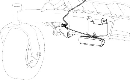
Secure the side light bracket to the platform using 2 self-tapping hex washer-head bolts as shown in Figure 5.
Insert the hex-head bolt (5/16 x 3/4 inch) through the LED light and side light bracket, and secure it with the flange nut (5/16 inch) as shown in Figure 6.
Parts needed for this procedure:
| Light switch bracket | 1 |
| Self-tapping screw (#10 x 1/2 inch) | 2 |
| Rocker switch | 1 |
| Light switch decal | 1 |
Install the light switch bracket using the 2 self-tapping screws (#10 x 1/2 inch) as shown in Figure 7.
Insert the rocker switch into the light switch bracket (Figure 8).
Apply the light switch decal to the light switch bracket (Figure 8).
Connect the wire-harness connector to the back of the rocker switch.
Parts needed for this procedure:
| Wire harness | 1 |
| Cable tie | 6 |
| Magnetic tie-wrap mount | 1 |
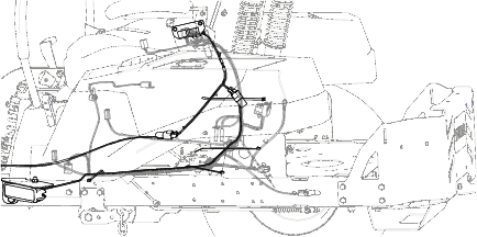
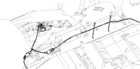
Beginning from the left side, route the wire harness next to the fuel tank, along the main machine wire harness (Figure 9).
Continue routing the wire harness underneath the seat plate, moving toward the controls (Figure 10).
Continue routing the wire harness toward the controls (Figure 10).
Secure the wire harness to the main machine wire harness using 4 cable ties as shown in Figure 9 and Figure 10.
Connect the side light wire-harness lead to the connector on the wire harness for the light kit (Figure 10).
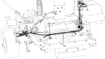
From the front of the machine, route the wire harness along the right side of the machine and attach the magnetic tie-wrap mount to the right pivot plate (Figure 11).
Continue to route the wire harness along the right side of the machine and secure the wire harness to the lift plate using 2 cable ties (Figure 12).
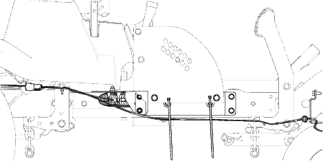
Route the wire harness between the right box control plate and the right deck-lift lever (Figure 13).
Connect the front light wire-harness lead to the connector on the wire harness for the light kit (Figure 13).
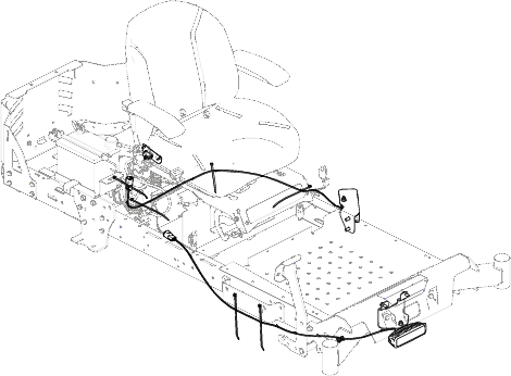
Use Figure 14 as an overview for routing the wire harness on a standard platform.
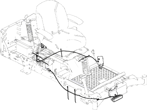
Use Figure 15 as an overview for routing the wire harness on a MyRide ™ platform.
Turn the key switch to the RUN position.
Test the light switch and verify that the lights are operating correctly.
If necessary, adjust the lights so that the light casts as desired.
Tighten all loose fasteners to complete the installation.