CALIFORNIA
Proposition 65 Warning
Read this information carefully to learn how to operate and maintain your product properly and to avoid injury and product damage. You are responsible for operating the product properly and safely.
You may contact Toro directly at www.Toro.com for product safety and operation training materials, accessory information, help finding a dealer, or to register your product.
Whenever you need service, genuine Toro parts, or additional information, contact an Authorized Toro Distributor or Toro Customer Service and have the model number of your product ready.
This product complies with all relevant European directives. For details, please see the Declaration of Incorporation (DOI) at the back of this publication.
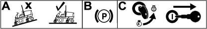
Close sectionPark the machine on a level surface.
Lower the cutting units.
Engage the parking brake.
Shut off the engine and remove the key.
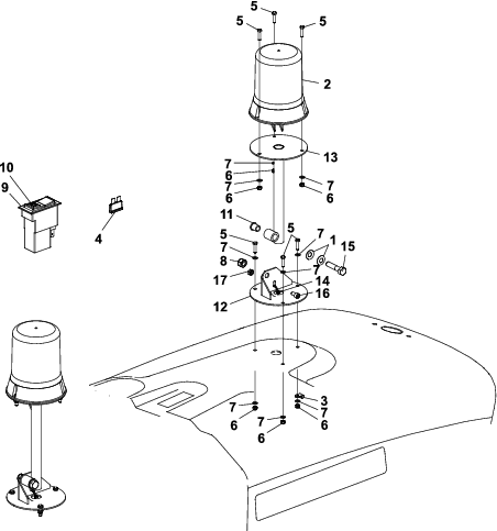
Parts needed for this procedure:
| Disc spring | 2 |
| Beacon assembly | 1 |
| Clip | 1 |
| Fuse (10 A) | 1 |
| Hex-head screw | 6 |
| Nyloc nut | 6 |
| Plain washer | 9 |
| Nyloc hex nut | 1 |
| Beacon switch | 1 |
| Beacon lens switch | 1 |
| Flanged bushing | 1 |
| Beacon base plate | 1 |
| Beacon upstand | 1 |
| Cable tie | 4 |
| Bolt (M12 x 55 mm) | 1 |
| Cap screw (M8 x 16 mm) | 1 |
| Hex nut | 1 |
| Grommet | 2 |
| Wiring loom | 1 |
| Adhesive clips | 10 |
Disconnect the negative (-) battery lead first and then disconnect the positive (+) battery lead.
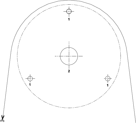
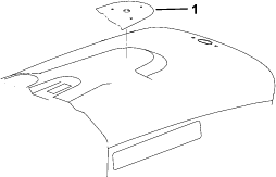
Align the hole template on the engine cover and drill the holes as shown in Figure 3 and Figure 6.
Raise the front platform to gain access to the control panel electrical connections.
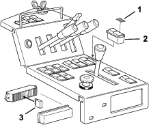
Remove a plug from behind the parking lever, and install the beacon switch into the opening (Figure 4).
From the existing loom, connect the orange wire terminal to the beacon switch terminal number 5 and the red/orange wire terminal to terminal number 1.
Assemble the beacon loom as follows:
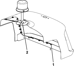
Fit the grommet over the bullet terminals on the cable (Figure 5).
Thread the cable through hole “A from the underside of the air-intake screen (Figure 5).
Insert the grommet around the cable into hole “A (Figure 5).
Fit the second grommet onto the cable.
Thread the cable through hole “B from inside the engine cover (Figure 5).
Insert the grommet into hole “B (Figure 5).
Remove the fuse box cover and connect the fuse (10 A) next to the fuse (3 A) as shown in Figure 4.
Secure the beacon wiring loom to the engine cover using the adhesive clips and evo-stick (if required), and ensure that the “P clip is fixed around the loom and to a securing screw (Figure 5).
Connect the loom terminals to the beacon terminals.
Locate the 2-pin sockets on the existing loom through the aperture in the rear of the chassis and connect it to the beacon loom.
Note: You may need to remove the rear guard plate to gain access.
Connect the positive (+) battery lead first and then the negative (-) battery lead.
Rotate the key to the “I position, depress the beacon switch and check that the beacon light rotates and flashes correctly.
Lower the front platform and secure the engine cover (Figure 3).