CALIFORNIA
Proposition 65 Warning
Use the following table to determine which kits your machine needs:
| Machine | Kit Name | Toro Part No. | Quantity Needed |
| Reelmaster 5210/5410/5510/5610 Series | Flexible Bottom Grass Basket Kit | 03415 | 5 |
| Rear Lift Cylinder Limit Kit | 110-9604 | 1 | |
| Groomer Rod Kit (only for units with groomers installed) | 131-6845 | 5 | |
| Reelmaster 5010-H Series with 5 or 7-inch cutting units | Flexible Bottom Grass Basket Kit (for front cutting units) | 03415 | 3 |
| Compact Flexible Bottom Grass Basket Kit (for rear cutting units) | 03416 | 2 | |
| Rear Lift Cylinder Limit Kit | 110-9604 | 1 | |
| Groomer Rod Kit (only for units with groomers installed) | 131-6845 | 5 | |
| Reelmaster 3550 Series with 18-inch cutting units | Flexible Bottom Grass Basket Kit (for front cutting units) | 03923 | 3 |
| Compact Flexible Bottom Grass Basket Kit (for rear cutting units) | 03924 | 2 | |
| Reelmaster 3550 Series with 22-inch rear cutting units | Flexible Bottom Grass Basket Kit (for front cutting units) | 03415 | 3 |
| Compact Flexible Bottom Grass Basket Kit (for rear cutting units) | 03416 | 2 | |
| Reelmaster 3555 with 5-inch cutting units and Reelmaster 3575 with 7-inch cutting units | Flexible Bottom Grass Basket Kit (for front cutting units) | 03415 | 3 |
| Compact Flexible Bottom Grass Basket Kit (for rear cutting units) | 03416 | 2 | |
| Groomer Rod Kit (only for units with groomers installed) | 131-6845 | 5 |
Note: Older Reelmaster 5010 series cutting units may be missing the threaded hole in the front height-of-cut brackets needed to install this kit (Figure 1). If your brackets are missing this threaded hole, contact your Authorized Toro Dealer to order replacement brackets (Toro Part No. 125-2796). Install the replacement brackets before installing the basket rod or groomer rod.

Parts needed for this procedure:
| Cylinder collar | 4 |
| Bolt | 4 |
| Flange locknut | 8 |
| Spacer | 2 |
| Stop bracket | 2 |
| Carriage bolt | 4 |
Note: The Rear Lift Cylinder Limit Kit (Toro Part No. 110-9604) is ordered separately. Contact an Authorized Toro Dealer to order the kit.
Position the traction unit on a level surface, lower the lift arms/cutting units, and shut the engine off. Remove the key from the ignition switch to prevent accidental starting.
Important: Mount the Rear Lift Cylinder Limit Kit on the number 2 and number 3 (rear) lift-arm cylinders only.
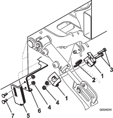
Install the cylinder collars to the extended cylinder rod with 2 bolts and 2 flange locknuts (Figure 2). Make sure that the cylinder collars fit over the top of the cylinder.
Loosely install the stop bracket to the deflector bracket with 2 carriage bolts and 2 locknuts (Figure 2).
Move the stop bracket to the highest position on the bracket and tighten the flange locknuts (Figure 2).
Note: The Rear Lift Cylinder Limit Kit (Toro Part No. 110-9604) is ordered separately. Contact an Authorized Toro Dealer to order the kit.
Position the traction unit on a level surface, lower the lift arms/cutting units, and shut the engine off. Remove the key from the ignition switch to prevent accidental starting.
Important: Mount the Rear Lift Cylinder Limit Kit on the number 2 and number 3 (rear) lift-arm cylinders only.
Install the cylinder collars and the spacer to the extended cylinder rod with 2 bolts and 2 flange locknuts (Figure 2).
Note: Make sure that the cylinder collars fit over the top of the cylinder and the spacer is flush with the cylinder end.
Loosely install the stop bracket to the deflector bracket with 2 carriage bolts and 2 locknuts (Figure 2).
Move the stop bracket to the lowest position on the bracket and tighten the flange locknuts (Figure 2).
Parts needed for this procedure:
| Basket guide—Model 03415 | 1 |
| Basket bracket—Model 03415 | 1 |
| Basket bracket—Model 03416 | 2 |
| Roll pin—Model 03415 | 1 |
| Roll pin—Model 03416 | 2 |
| Left torsion spring (gold)—Models 03415 and 03416 | 1 |
| Right torsion spring (black)—Models 03415 and 03416 | 1 |
| Basket collar—Model 03415 | 1 |
| Basket collar—Model 03416 | 2 |
| Flat washer (3/8 x 7/8 inch)—Models 03415 and 03416 | 2 |
| Bolt (5/16 x 1-1/4 inches)—Model 03415 | 1 |
| Bolt (5/16 x 1/2 inch)—Model 03415 | 1 |
| Bolt (5/16 x 1/2 inch)—Model 03416 | 2 |
| Plastic washer—Model 03415 | 1 |
| Plastic washer—Model 03416 | 2 |
Remove the cutting units from the cartons. Assemble and adjust them according to the Operator’s Manual for the cutting unit.
Use Figure 3 or Figure 4 to determine the locations where the basket guides (red) or basket brackets (black) must be mounted to the carrier frames.
Note: Figure 3 applies to Reelmaster 5210/5410/5510/5610 series. Figure 4 applies to Reelmaster 3550 Series and 5010-H series.
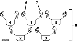
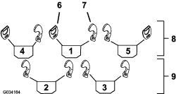
Mount a basket guide to the appropriate side of each carrier frame (Figure 3) with a bolt (5/16 x 1/2 inch) and a flat washer (3/8 x 7/8 inch). Position the components as shown in Figure 5.
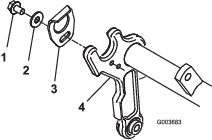
Install a roll pin into the lower hole in the appropriate side of each cutting-unit carrier frame (Figure 6).
Note: The end of the roll pin should be flush with the inner side of the carrier frame.
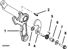
On the same side of the carrier frame that the roll pin is installed, mount a plastic washer, basket bracket, torsion spring, basket collar, flat washer (3/8 x 7/8 inch), and bolt (5/16 x 1-1/4 inches); refer to Figure 6.
Note: The plastic washer, basket bracket, and torsion spring fit onto the basket collar.The gold torsion spring is for the left side of the carrier frame and the black spring is for the right side of the carrier frame. Position the longer leg of the spring around the front of the carrier frame and insert the shorter, rear leg of the spring into the hole in the basket bracket.
Ensure that the basket bracket rotates freely.
Important: The plastic washer must be installed onto the basket collar to prevent binding.
Parts needed for this procedure:
| Cutoff bar | 1 |
| Bolt (1/4 x 1-3/4 inches) | 4 |
| Locknut (1/4 inch) | 4 |
Loosely mount the cutoff bar to the cutting-unit frame with 4 bolts (1/4 x 1-3/4 inches) and 4 locknuts (1/4 inch); refer to Figure 7.
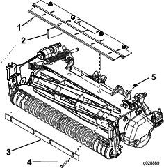
Insert a 0.060-inch feeler gauge between the top of the reel and the bottom of the cutoff bar to check the clearance. Make sure that the bar and the reel are equal distance apart across the full length of the reel.
Note: The cutoff bar must not contact the reel during operation.
Tighten the bolts and locknuts (Figure 7).
Skip this procedure if grass deflectors are not installed.
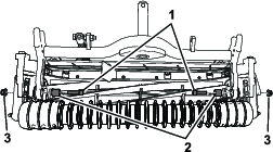
Remove the 4 flange-head bolts securing the front grass shield to the cutting-unit frame (Figure 7). Remove the grass shield.
Remove 4 deflectors from the shield leaving only the 1 deflector shown in Figure 7.
Install the grass shield.
Parts needed for this procedure:
| Spacer | 2 |
| Bolt (3/8 x 1-1/4 inches) | 2 |
| Flange locknut (3/8 inch) | 2 |
Unthread the 2 flange-head bolts securing the support tube and the cutting-unit carrier frame to the cutting-unit side plates (Figure 9). Do not pull the bolts all the way out of the carrier frame. Remove the support tube.
Important: Install the new bolts, spacers, and flange locknuts even if there is no support tube installed (Figure 8).
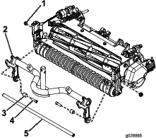
Secure the carrier frame to the cutting-unit side-plates with 2 spacers, 2 bolts (3/8 x 1-1/4 inches), and 2 flange locknuts (3/8 inch); refer to Figure 9.
Parts needed for this procedure:
| Flange nut (3/8 inch) | 2 |
| Basket plate | 2 |
| Flange screw (5/16 inch) | 2 |
| Basket rod | 1 |
| Hardened washer | 1 |
| Flange nut (5/16 inch) | 1 |
| Carriage bolt (3/8 x 1-3/4 inches) | 2 |
Note: This procedure is for cutting units without groomers installed. If the cutting unit has groomers installed, skip this procedure.
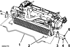
Install a basket plate on each side of the cutting-unit frame using 1 flange nut (3/8 inch), 1 carriage bolt (3/8 x 1-3/4 inches), and 1 flange screw (5/16 inch); refer to Figure 10.
Insert the long hexagonal end of the basket rod into 1 basket plate and the other end into the other basket plate (Figure 10).
Secure the short hexagonal end of the rod with a flange nut (5/16 inch) and a hardened washer (Figure 10).
Important: Ensure that the basket rod does not touch the front roller.
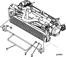
Parts needed for this procedure:
| Groomer rod | 1 |
| Bolt (M10 x 12 mm) | 1 |
| Washer | 2 |
Note: This procedure is for cutting units with groomers installed and replaces the items in Installing the Basket Rod (Units Without Groomers Only). The Groomer Rod Kit (Toro Part No. 131-6845) is ordered separately; contact an Authorized Toro Dealer to order the kit.
Install the kit as shown in Figure 11.
Parts needed for this procedure:
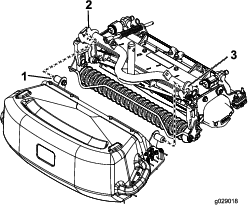
| Basket assembly | 1 |
Mount a basket to each cutting-unit carrier frame by inserting the basket mounting pin into the basket-guide bracket and pressing the opposite mounting pin into the pivoting basket bracket (Figure 12).
Important: Ensure that the front of the basket does not contact the reel. If there is contact, refer to Adjusting the Basket Position.
Make sure that the basket is parallel to the cutting unit with a minimum clearance of 6 mm (0.250 inch) between the lip of the basket and the reel. If an adjustment to the basket position is required, proceed as follows:
On each side of the basket, loosen the nuts on the carriage bolts securing the basket stop brackets to the basket (Figure 13).
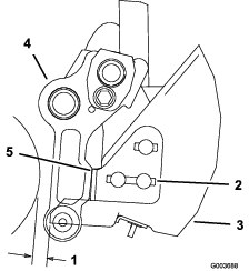
Position the basket so that it is parallel to the cutting unit with a minimum clearance of 6 mm (0.250 inch) between the lip of the basket and the reel (Figure 13).
On each side of the basket, adjust the basket stop brackets so that they each contact a carrier-frame arm.
Tighten the nuts on the carriage bolts to secure the basket position.