Introduction

This machine is designed for use on Toro compact tool carriers to grind and remove tree stumps and surface roots. It is not intended to cut rock or any other material other than wood and the soil around a stump.

Read this information carefully to learn how to operate and maintain your product properly and to avoid injury and product damage. You are responsible for operating the product properly and safely.

You may contact Toro directly at www.Toro.com for product safety and operation training materials, accessory information, help finding a dealer, or to register your product.

Whenever you need service, genuine Toro parts, or additional information, contact an Authorized Service Dealer or Toro Customer Service and have the model and serial numbers of your product ready. Figure 1 identifies the location of the model and serial numbers on the product. Write the numbers in the space provided.

g013652

This manual identifies potential hazards and has safety messages identified by the safety-alert symbol (Figure 2), which signals a hazard that may cause serious injury or death if you do not follow the recommended precautions.

g000502

This manual uses 2 words to highlight information. Important calls attention to special mechanical information and Note emphasizes general information worthy of special attention.

This product complies with all relevant European directives. For details, please see the Declaration of Incorporation (DOI) at the back of this publication.

Warning

CALIFORNIA

Proposition 65 Warning

This product contains a chemical or chemicals known to the State of California to cause cancer, birth defects, or reproductive harm.

Use of this product may cause exposure to chemicals known to the State of California to cause cancer, birth defects, or other reproductive harm.

Close section

Safety

Improper use or maintenance by the operator or owner can result in injury. To reduce the potential for injury, comply with these safety instructions and those in the traction unit Operator's Manual. Always pay attention to the safety alert symbol, which means Caution, Warning, or Danger—personal safety instruction. Failure to comply with the instruction may result in personal injury or death.

Danger

There may be buried power, gas, and/or telephone lines in the work area. Shock or explosion may occur if you dig into them.

Have the property or work area marked for buried lines and do not dig in marked areas. Contact your local marking service or utility company to have the property marked (for example, in the United States, call 811 for the nationwide marking service).

Danger

The stump grinder is solely designed and tested for grinding stumps less than 91 cm (36 inch) tall. Any other uses may cause a hazardous situation resulting in injury or death to you or bystanders.

Only use the stump grinder for grinding stumps less than 91 cm (36 inch) tall.

Warning

When the engine is off, attachments in the raised position can gradually lower. Someone nearby may be pinned or injured by the attachment as it lowers.

Always lower the attachment lift each time you shut off the traction unit.

Warning

During operation, debris will fly in all directions and can cause injury to eyes and other exposed body parts.

  • Never operate the stump grinder without the shield installed on the traction unit and the chip guard on the grinder.

  • Wear personal protective gear during operation.

  • Keep all bystanders at least 9 m (30 ft) away from the work area.

Warning

When going up or down hill, the machine could overturn if the heavy end is toward the downhill side. Someone may be pinned or seriously injured by the machine if it overturns.

Operate up and down slopes with the heavy end of the machine uphill. This attachment makes the front end heavy.

Warning

If you do not fully seat the attachment locking pins in the attachment mount plate holes, the attachment could fall off the traction unit and severely injure you or bystanders.

  • Ensure that you fully seat the attachment locking pins through the holes in the attachment mount plate before lifting the attachment.

  • Ensure that the attachment mount plate is free of any dirt or debris that may hinder the connection of the traction unit to the attachment.

  • Refer to your traction unit Operator’s Manual for detailed information on safely connecting an attachment to your traction unit.

Warning

Lightning can cause severe injury or death.

If lightning is seen or thunder is heard in the area, do not operate the machine; seek shelter.

Caution

Hydraulic fluid escaping under pressure can penetrate skin and cause injury. Fluid injected into the skin must be surgically removed within a few hours by a doctor familiar with this form of injury; otherwise, gangrene may result.

  • Keep your body and hands away from pinhole leaks or nozzles that eject high-pressure hydraulic fluid.

  • Use cardboard or paper to find hydraulic leaks, never use your hands.

Caution

Hydraulic couplers, hydraulic lines/valves, and hydraulic fluid may be hot and can burn you if you touch them.

  • Wear gloves when operating the hydraulic couplers.

  • Allow the traction unit to cool before touching hydraulic components.

  • Do not touch hydraulic fluid spills.

Stability Ratings

To determine the degree of slope you can traverse with the stump grinder installed on a traction unit, find the stability rating for the hill position you want to travel in the appropriate table below, then find the degree of slope for the same rating and hill position in the Stability Data section of the traction unit Operator’s Manual.

Warning

Exceeding the maximum recommended slope can cause the traction unit to tip, crushing you or bystanders.

Do not drive the traction unit on a slope steeper than the maximum recommended slope, as determined in the following tables and the traction unit Operator's Manual.

Important: If you have a traction unit other than a TX compact utility loader, do not use the counterweight on the traction unit when using the stump grinder. If you use the counterweight, the traction unit will be less stable in the front and side uphill positions.

OrientationStability Rating
Front UphillD
Graphic
Rear UphillC
Graphic
Side UphillC
Graphic
Close section

Safety and Instructional Decals

Graphic

Safety decals and instructions are easily visible to the operator and are located near any area of potential danger. Replace any decal that is damaged or missing.

decal136-5814
decal136-5817
decal136-5818
Close section
Close section

Setup

Installing the Shield Brackets

Parts needed for this procedure:

Right shield bracket (3 holes)—200/300 Series or TX 400/500 Series only1
Left shield bracket (3 holes)—200/300 Series or TX 400/500 Series only1
Self-tapping screw (5/16 x 3/4 inch)4
Right shield bracket (2 holes)—TX 1000 only1
Left shield bracket (2 holes)—TX 1000 only1
Bolt (1/4 x 3/4 inch)—TX 1000 only4
Locknut (1/4 inch)—TX 1000 only4

200 or 300 Series Traction Unit Only

Important: Use the shield brackets with 3 holes.

  1. Insert the tab on the shield bracket into the lift-point hole on the traction unit, with the hole in the bracket aligning with the small hole in the traction unit frame (Figure 3).

    Note: There is a right and left bracket. Ensure that you install the correct bracket on each side. The tab should be in the lift-point hole and the bracket should be on the outside of the frame (Figure 3).

    g013653
  2. Secure the bracket to the frame with a self-tapping screw (Figure 3).

  3. Repeat steps 1 and 2 for the other side of the traction unit.

Close section

TX 400 or 500 Series Traction Unit Only

Important: Use the shield brackets with 3 holes.

  1. Measure in from the edges of the frame as illustrated in Figure 4 and mark the locations of the holes for mounting the shield bracket.

    Note: If the holes exist, skip to step 3.

    g203568
  2. Drill a hole (5/16 inch diameter) through the frame at each marked location.

  3. Align the tab on the shield bracket with the front edge of the frame with the bracket inside of the loader-arm pocket (Figure 5).

    Note: There is a right and left bracket. Ensure that you install the correct bracket on each side. The tab should be over the frame edge and the bracket should be inside the loader-arm pocket with the 2 smaller holes in the bracket lined up with the holes you drilled in the frame (Figure 5).

    g013655
  4. Secure the bracket to the frame with 2 self-tapping screws as illustrated in Figure 5.

  5. Repeat steps 1 through 4 for the other side of the traction unit.

Close section

TX 1000 Traction Unit Only

Important: Use the shield brackets with 2 holes.

  1. Measure in from the edges of the frame as illustrated in Figure 6 and mark the locations of the holes for mounting the shield bracket.

    Note: If the holes exist, skip to step 3.

    g202805
  2. Drill a hole (9/32 inch diameter) through the frame at each marked location.

  3. Install the left shield bracket on the left frame using 2 bolts (1/4 x 3/4 inch) and 2 Locknuts (1/4 inch) as shown in Figure 7.

    g202825
  4. Install the right shield bracket on the right frame 2 bolts (1/4 x 3/4 inch) and 2 locknuts (1/4 inch), similar to Figure 7.

Close section
Close section

Assembling the Operator Shield

Parts needed for this procedure:

Shield support (1 bend)—200/300 Series or TX 400/500 Series2
Shield support (2 bends)—TX 1000 only2
Shield1
Bolt (1/4 x 1-1/2 inch)8
Washer8
Locknut (1/4 inch)8

Assembling the Shield

Note: Use the shield supports with 1 bend for 200/300 series or TX 400/500 series traction units. Use the shield supports with 2 bends for TX 1000 traction units.

  1. Slide the shield supports into the pockets in the shield brackets on the traction unit (Figure 8).

    g202610
    g202842
  2. Assemble the shield and flexible skirt to the shield supports as illustrated in Figure 8, using 8 bolts (1/4 x 1-1/2 inch), 8 washers, and 8 locknuts (1/4 inch).

    Note: The skirt should drape over the engine or hood.

Close section
Close section

Installing the Chip Guard

Parts needed for this procedure:

Chip guard1
Guard pin1
Hairpin cotter1

The stump grinder has 4 sets of mounting holes for positioning the chip guard (Figure 10). Move the guard up (upper holes) when you are grinding close to the ground and down (lower holes) when you are chipping tall stumps. Install the chip guard as follows:

  1. Position the mounting tube on the guard between 2 holes on the grinder (Figure 10).

    g202609
  2. Slide the guard pin through the holes in the grinder and the mounting tube (Figure 10).

  3. Secure the pin with a hairpin cotter (Figure 10).

Close section
Close section

Product Overview

g013651

Note: Specifications and design are subject to change without notice.

Width, with chip guard112 cm (44 inches)
Width, without chip guard66 cm (26 inches)
Length51 cm (20 inches)
Height79 cm (31 inches)
Weight120 Kg (265 lb)

Attachments/Accessories

A selection of Toro approved attachments and accessories is available for use with the machine to enhance and expand its capabilities. Contact your Authorized Service Dealer or Distributor or go to www.Toro.com for a list of all approved attachments and accessories.

Close section
Close section

Operation

Warning

During operation, debris will fly in all directions and can cause injury to eyes and other exposed body parts.

  • Never operate the stump grinder without the shield installed on the traction unit and the chip guard on the grinder.

  • Wear personal protective gear during operation.

  • Keep all bystanders at least 9 m (30 feet) away from the work area.

Refer to your traction unit Operator’s Manual for more information on installing and removing attachments on your traction unit.

Important: Always use the traction unit to lift and move the attachment.

Grinding Stumps

  1. If your traction unit has a speed selector, set it to the SLOW position.

  2. Start the engine.

  3. Pull the auxiliary hydraulics lever to the operator grip to engage the stump grinder.

  4. Position the grinder on the left side and behind the stump (Figure 12).

    g013658
  5. Swing the grinder toward you using the attachment-tilt lever, grinding at a depth of 0.5 to 5 cm (1/4 to 2 inches), depending on the hardness of the wood (Figure 12).

    Note: If you cut too deep, the grinder stalls. If it stalls, raise it slightly and try again.

  6. Swing the grinder back out (Figure 12), lower it 0.5 to 5 cm (1/4 to 2 inches), and repeat steps 4 through 6 until you have ground down a few inches.

  7. Raise the loader arms to the original height.

  8. Move the grinder to the right (Figure 12).

  9. Repeat steps 4 through 8 until you reach the right side of the stump.

  10. Return the grinder to the left side of the stump, lower it, and repeat steps 3 through 10 until you have ground the stump into the ground.

    Note: To contain the chips, you may need to stop the grinder and move the chip guard up as you move the grinder down.

  11. When finished, stop the grinder by moving the auxiliary hydraulics lever into neutral.

Close section

Grinding Roots

  1. Stop the grinder and hang it vertically from the loader arms a few centimeters (inches) off the ground.

  2. Shut off the engine and remove the key.

  3. Loosen the large bolt on the top of the grinder (Figure 13).

    g013659
  4. Remove the front bolt and nut securing the grinder (Figure 13).

  5. Swing the grinder 30 degrees clockwise (Figure 13).

  6. Torque the large bolt on top of the grinder to 406 N∙m (300 ft-lb) as shown in Figure 13.

  7. Install the bolt and nut in the front hole and torque them to 101 N∙m (75 ft-lb) as shown in Figure 13.

  8. Start the traction unit and start the grinder.

  9. Lower the grinder into the root.

  10. Move the grinder along the length of the root by moving the traction unit over the root.

  11. When finished, stop the grinder by moving the auxiliary hydraulics lever into neutral.

  12. Shut off the engine and remove the key.

  13. Loosen the large bolt on the top of the grinder (Figure 13).

  14. Remove the front bolt and nut securing the grinder (Figure 13).

  15. Swing the grinder 30 degrees counter-clockwise (Figure 13).

  16. Torque the large bolt on top of the grinder to 406 N∙m (300 ft-lb) as shown in Figure 13.

  17. Install the bolt and nut in the front hole and torque them to 101 N∙m (75 ft-lb) as shown in Figure 13.

Close section

Transporting the Stump Grinder on a Trailer

Place the attachment on a trailer or truck capable of carrying it. Securely tie it to the trailer or truck using tie straps appropriate for the weight of the attachment and for highway use.

Important: Remove the operator's shield before transporting the traction unit to avoid damage to the shield of the traction unit.

Close section

Operating Tips

  • Always use full throttle (maximum engine speed).

  • Never transport the attachment with the loader arms raised. Keep the arms lowered and the attachment tilted up.

  • If your traction unit has a speed selector (present on some wheeled traction units), set it to the slow (turtle position).

  • If your traction unit has a flow divider (present on some wheeled traction units), adjust it to approximately the 10 o’clock position.

Close section
Close section

Maintenance

Recommended Maintenance Schedule(s)

Maintenance Service IntervalMaintenance Procedure
Before each use or daily
  • Grease the machine.
  • Check the condition of the teeth and rotate or replace any that are worn or damaged.
  • Before storage
  • Grease the machine.
  • Paint chipped surfaces.
  • Caution

    If you leave the key in the ignition switch, someone could start the engine. Accidental starting of the engine could seriously injure you or bystanders.

    Remove the key from the ignition switch before you do any maintenance.

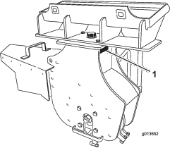
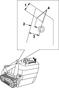
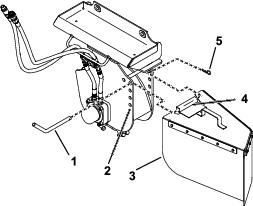
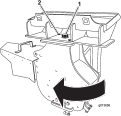
    Greasing the Machine

    Grease the fitting in Figure 14.

    g203602

    Grease Type: General-purpose grease

    1. Park the traction unit on a level surface, engage the parking brake (if equipped) and lower the loader arms.

    2. Shut off the engine and remove the key.

    3. Clean the grease fitting with a rag.

    4. Connect a grease gun to the fitting.

    5. Pump grease into the fitting until grease begins to ooze out of the bearings.

    6. Wipe up any excess grease.
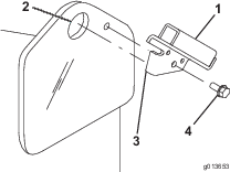
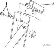
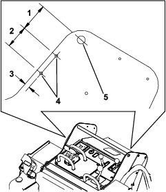
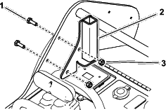
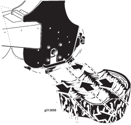
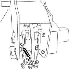
    Close section

    Replacing the Teeth

    Due to the high amount of wear placed on the teeth, you will need to rotate and replace them periodically.

    Each tooth is indexed with three positions so you can rotate it twice, exposing a new sharp edge before replacing the tooth. To rotate a tooth, loosen the nut securing the tooth (Figure 15). Push the tooth forward and rotate it one third of a turn, bringing an unused edge to the outside. Torque the nut securing the tooth to 37 to 45 N∙m (27 to 33 ft-lb).

    g013417

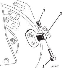
    To replace a tooth, remove the nut securing the tooth to remove it, then install a new tooth and nut in the same position (Figure 15). Torque the nut securing the tooth to 37 to 45 N∙m (27 to 33 ft-lb).

    Close section
    Close section

    Storage

    1. Before long term storage, brush the dirt from the attachment.

    2. Check the condition of the teeth. Turn or replace any worn or damaged teeth.

    3. Check and tighten all bolts, nuts, and screws. Repair or replace any part that is damaged or worn.

    4. Ensure that all hydraulic couplers are connected together to prevent contamination of the hydraulic system.

    5. Paint all scratched or bare metal surfaces. Paint is available from your Authorized Service Dealer.

    6. Store the attachment in a clean, dry garage or storage area. Cover it to protect it and keep it clean.

    Close section

    Troubleshooting

    ProblemPossible CauseCorrective Action
    Cutting disk stops during cutting.
    1. You are cutting too deep.
    2. Teeth are worn, damaged, or broken.
    1. Raise the loader arms 13 mm (1/2 inch).
    2. Rotate or replace any worn, damaged, or broken teeth.
    The cutting disk does not turn or turns slowly.
    1. A hydraulic coupler is not completely connected.
    2. A hydraulic coupler is damaged.
    3. There is an obstruction in a hydraulic hose.
    4. An auxiliary valve on the traction unit is not opening.
    5. The hydraulic motor or drive has failed.
    6. The check valve brake is reversed.
    1. Check and tighten all couplers.
    2. Check/replace couplers.
    3. Find and remove the obstruction.
    4. Repair the valve.
    5. Contact your Authorized Service Dealer.
    6. Reverse the check valve direction; contact your Authorized Service Dealer.
    The grinder does not cut fast enough.
    1. Teeth are worn.
    2. The setting is wrong on the flow divider and speed lever (applicable wheeled units only).
    3. There is a restriction in a quick coupler or hose.
    4. The hydraulic system is too hot.
    5. The relief valve is set below specifications.
    1. Rotate or replace any worn teeth.
    2. Set the flow divider to the 10:00 position and the speed lever to the turtle position.
    3. Check the hoses and couplers and repair any problems found.
    4. Shut the system down and allow it to cool.
    5. Contact your Authorized Service Dealer.
    The cutting disk turns in the wrong direction
    1. The auxiliary-valve lever is in the wrong position.
    2. The hydraulic hoses are reversed.
    1. Move the auxiliary-valve lever to the rearward position.
    2. Disconnect the hoses and switch positions.
    Close section