


Maintenance
Inspect the Filter
| Maintenance Service Interval | Maintenance Procedure |
|---|---|
| After the first 5 hours |
|
| Every 50 hours |
|
-
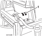
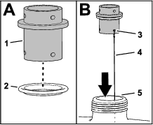
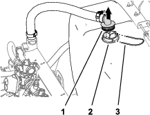
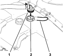
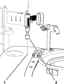
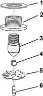
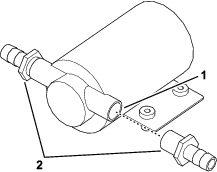
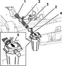
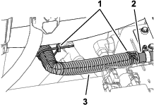
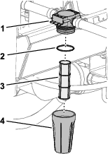
Rotate the filter counterclockwise to remove the bowl from the filter head (Figure 41).
-
Inspect the filter element for damage or an accumulation sediment or debris (Figure 41).
Replace a damaged filter element. if there is an accumulation sediment or debris, clean the element as follows:
-
Inspect the O-ring for damage (Figure 41).
Replace the O-ring if it is damaged.
-
Thread the bowl clockwise into the filter head, and tighten by hand (Figure 41).
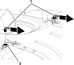
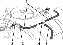
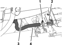
Inspecting the Rinse System for Leaks and Damage
| Maintenance Service Interval | Maintenance Procedure |
|---|---|
| After the first 5 hours |
|
| Before each use or daily |
|
| Every 100 hours |
|
Contact your Authorized Toro Dealer to obtain replacement parts.
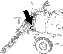
Inspecting the Rinse Tank Hold Downs
| Maintenance Service Interval | Maintenance Procedure |
|---|---|
| After the first hour |
|
| Yearly |
|
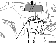
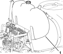
Once the main tank has been filled with water, check to see if there is any play in the tank straps. If the straps are loose, tighten the fasteners at the top straps until they are flush with tank. Do not over tighten.
-
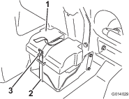
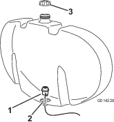
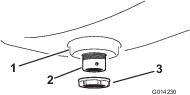
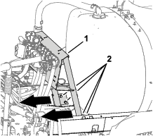
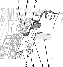
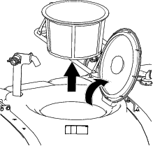
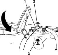
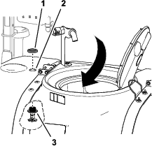
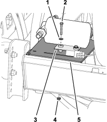
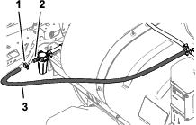
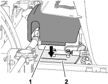
Fill the rinse tank with clean water (Figure 42).

-
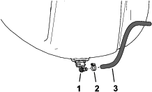
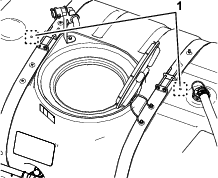
Check for play between the hold downs and the rinse tank (Figure 42).
-
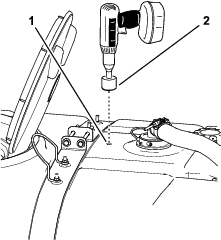
If you find play between the hold downs and the rinse tank, tighten bolt(s) and flange locknut(s) until the hold downs are snug against the rinse tank (Figure 42).
Note: Do not overtighten the bolt(s) and locknut(s) of the hold down(s), or deform the tank.
Important: Overtightening the tank strap fasteners can deform and damage the hold downs.