Warning

CALIFORNIA

Proposition 65 Warning

Note: Determine the left and right sides of the machine from the normal operating position.

This product complies with all relevant European directives. For details, please see the Declaration of Incorporation (DOI) at the back of this publication.

Electromagnetic Compatibility
Domestic: This device complies with FCC Rules Part 15. Operation is subject to the following two conditions: (1) This device may not cause harmful interference and (2) this device must accept any interference that may be received, including interference that may cause undesirable operation.
This equipment generates and uses radio frequency energy and if not installed and used properly, in strict accordance with the manufacturer's instructions, may cause interference to radio and television reception. It has been type tested and found to comply within the limits of a FCC Class B computing device in accordance with the specifications in Subpart J of Part 15 of FCC Rules, as stated above. However, there is no guarantee that interference will not occur in a particular installation. If this equipment does cause interference to radio or television reception, which can be determined by turning the equipment off and on, the user is encouraged to try to correct the interference by one or more of the following measures:Reorient the receiving antenna, relocate the remote control receiver with respect to the radio/TV antenna or plug the controller into a different outlet so that the controller and radio/TV are on different branch circuits.If necessary, the user should consult the dealer or an experienced radio/television technician for additional suggestions.The user may find the following booklet prepared by the Federal Communications Commission helpful: "How to Identify and Resolve Radio-TV Interference Problems". This booklet is available from the U.S. Government Printing Office, Washington, DC 20402. Stock No. 004-000-00345-4.
FCC ID: OA3MRF24J40MC-Base, OA3MRF24J40MA-Hand Held
IC: 7693A-24J40MC-Base, 7693A-24J40MA-Hand Held
Operation is subject to the following two conditions: (1) this device may not cause interference, and (2) this device must accept any interference, including interference that may cause undesired operation of the device.
Japan Electromagnetic Compatibility Certification
Handheld:Graphic
RF2CAN:Graphic
Mexico Electromagnetic Compatibility Certification
Handheld:Graphic
RF2CAN:Graphic
Korea Electromagnetic Compatibility Certification(Decal provided in separate kit)
Handheld:Graphic
RF2CAN:Graphic
Singapore Electromagnetic Compatibility Certification
Handheld:TWM240007_IDA_N4022-15
RF2CAN:TWM-240005_IDA_N4024–15

Safety

Safety and Instructional Decals

Graphic

Safety decals and instructions are easily visible to the operator and are located near any area of potential danger. Replace any decal that is damaged or missing.

decal131-6766
decal136-7585
Close section
Close section

Setup

Preparing the Machine

  1. Park the machine on a level surface.

  2. Raise the hopper and secure it in place with the cylinder lock.

  3. Disconnect the power connector from the traction unit.

  4. Ensure that the machine is secure from movement before you begin the installation.

Close section

Removing the Components

Only When Upgrading
  1. Remove the hardware securing the compartment cover and set it aside (Figure 1).

    g035406
  2. Disconnect the wire harness from all the components except the relays (Figure 2).

    g035407
  3. Remove all the hardware securing the components on the inside of the compartment (Figure 2).

  4. Remove all the components except for the audio alarm from the compartment (Figure 2).

  5. Remove the retaining nuts and washers from the front of the proximity sensors on the right side sensor plate and set them aside (Figure 3).

    g035408
  6. Remove the proximity sensors from the right sensor plate and set them aside.

  7. Remove the carriage bolts and flange nuts securing the right sensor plate to the frame (Figure 3).

  8. Remove the carriage bolts and flange nuts securing the left sensor plate to the frame (Figure 4).

    g035735
Close section

Drilling the Holes

  1. Locate and drill the following hole for the plug cap (Figure 5).

    g035409
  2. Locate and drill the following holes for the fuse block and relay (Figure 6).

    g035410
  3. Locate and drill the following holes for the transmitter (Figure 7).

    Note: You can use the transmitter as a template.

    g035411
  4. Locate and drill the following holes for the controller (Figure 8).

    Note: You can use the controller as a template.

    g035412
  5. Locate and drill the following hole for the controller (Figure 9).

    g035660

    Note: Ensure that you do not oversize the hole.

Close section

Installing the Decals

Parts needed for this procedure:

Fuse decal1
Electrical update decal1
  1. Ensure that the application surface is clean.

  2. Locate and apply the fuse decal at the location shown (Figure 10).

    g035413
  3. Apply the electrical update decal next to the serial tag on the machine.

Close section

Installing the Components

Parts needed for this procedure:

Radio transmitter1
Radio controller1
Indicator lamp1
Relay1
Bolt (1/4 x 1-1/8 inches)8
Bolt (1/4 x 3/4 inch)3
Bolt (#10 x 7/8 inch)1
Flange nut (1/4 inch)11
Locknut (#10)1
  1. Use the 4 bolts (1/4 x 3/4 inch) and flange nuts to secure the transceiver (Figure 11).

    g035414
  2. Use the 4 bolts (1/4 x 3/4 inch) and flange nuts to secure the controller (Figure 12).

    g035415
  3. Use the bolt (1/4 x 3/4 inch) and flange nut to secure the relay (Figure 13).

    g035448
  4. Remove the fuse cap from the wire harness.

  5. Use the 2 bolts (1/4 x 3/4 inch) and flange nuts to secure the fuse cap (Figure 14).

    g035449
  6. Insert the connector through the mount hole in the cover panel (Figure 15).

    g035450

    Note: Ensure that the gasket is installed between the cover and indicator light (Figure 15).

  7. Use the retaining nut and lock washer to secure the indicator light to the mount hole in the cover panel (Figure 15).

  8. Remove the plug cap from the wire harness.

  9. Use the bolt (#10 x 7/8 inch) and locknut to secure the plug cap to the controller box (Figure 16).

    g035456
Close section

Installing the Proximity Sensors

Parts needed for this procedure:

Right sensor plate1
Left sensor plate1
Proximity sensor1
  1. Use the 2 carriage bolts (3/8 x 1 inch) and flange nuts to secure the right sensor plate to the machine (Figure 17).

    g035665
  2. Use the retaining nuts and washers to secure the proximity sensors that you removed earlier to the right sensor plate (Figure 17).

    Important: Ensure that you do not damage the front of the sensor when it is installed.

  3. Use the carriage bolt (3/8 x 1 inch) and flange nut to secure the left sensor plate to the machine (Figure 18).

    g035451
  4. Use the retaining nut and washer to secure the proximity sensor included in the kit to the left sensor plate (Figure 18).

    Important: Ensure that you do not damage the front of the sensor when it is installed.

  5. Set a 3.6 mm (0.14 inch) sensor gap to each sensor that you installed (Figure 19).

    g035664

    Important: Ensure that you do not damage the front of the sensor when you set the sensor gap.

Close section

Installing the Wire Harness

Parts needed for this procedure:

Wire harness1
Cable tie10
Cable-tie clip2
  1. Route the wire harness onto the frame of the tow-behind vehicle (Figure 20).

    g035676

    Note: Ensure that you route the wire harness through the hose rings at the front of the tow-behind vehicle.

  2. Use the cable-tie clips that are on the wire harness to secure it to the frame.

  3. Follow the color code and connector keying to ensure that you are installing the appropriate connector to the component plug (Figure 21).

    g035674
  4. Connect the wire harness to the hydraulic manifold (Figure 22).

    g035675
  5. Connect the wire harness to the appropriate proximity sensor (Figure 23 and Figure 24).

    g035677
    g035703
  6. Install the cable-tie clips to the left and right sensor plate (Figure 23 and Figure 24).

  7. Insert the cable ties through the clip and around the wire harness connectors to secure it to the sensor plate (Figure 23) and Figure 24).

  8. Use cable ties to secure the wire harness to the hydraulic hoses (Figure 25).

    g035901
Close section

Installing the Cover

Parts needed for this procedure:

Compartment cover1
  1. Connect the indicator light to the wire harness (Figure 26).

    g035457
  2. Use the bolt (3/8 x 1 inch) and nut that you removed earlier to secure cover to the compartment (Figure 26).

Close section

Assembling the Handheld Remote

Parts needed for this procedure:

Handheld remote1
AA battery4
  1. Remove the rubber bands securing the remote halves together, and remove the back cover.

  2. Install the batteries into the terminal cradle observing proper polarity (Figure 27).

    g035673

    Note: The controller cannot function when the batteries are installed improperly.

  3. Replace the cover and secure it with the 6 screws removed previously (Figure 27) and torque them to 1.5 to 1.7 N∙m (13 to 15 in-lb).

    Note: Do not overtighten the screws.

Close section
Close section

Product Overview

Hopper Dump Button

To dump the hopper, press the hopper dump button 2 times (Figure 28).

Important: The sweeper must be directly behind the traction unit and in transport height before you can activate the dump sequence.

g030468
Close section

Sweeper Down Button

To lower the hopper, press the sweeper down button (Figure 28). You can lower the hopper at any of the following positions:

  • Hopper dump height

  • Transport height

  • Turn around height

    Note: When lowering the hopper from the dump position, you can stop the lower hopper function at any time by releasing the sweeper down button.

    Note: With the sweeper in the transport or turn around positions, the lower hopper function can be stopped at any time by pressing the sweeper up button.

Close section

Sweeper Up Button

Standard Mode

To raise the sweeper in standard mode, press the sweeper up button. The hopper stops at the pre-defined height (Figure 28).

  • Transport height (home position) is 13-1/4 to 15-1/4 inches.

  • Turn around height (offset position) is 8-1/2 to 10-1/2 inches.

Close section

Sweeper Up Button

Optional Mode

This mode allows the operator to adjust the sweeper to any desired height and it stops at the pre-defined heights.

Note: Refer toSwitching the Sweeper-Up Mode to switch to the optional mode.

To raise the sweeper in optional mode, press and hold the sweeper up button until the hopper reaches the desired height or stops at the pre-defined height (Figure 28).

  • Transport height (home position) is 13-1/4 to 15-1/4 inches.

  • Turn around height (offset position) is 8-1/2 to 10-1/2 inches.

Close section

Offset Left Button

To offset the sweeper to the left, press and hold the offset left button (Figure 28). Releasing the button stops the movement to the left.

Close section

Offset Right Button

To offset the sweeper to the right, press and hold the offset right button (Figure 28). Releasing the button stops the movement to the right.

Close section

Stop Button

Pressing the stop button disables any active function.

Note: There is approximately a 3 second delay.

Close section

Diagnostic Light

The diagnostic light (Figure 29) is located on the compartment cover and indicates machine fault codes. After you turn the key to the RUN position, the diagnostic light illuminates for 5 seconds, turns off for 5 seconds, and then begins flashing 3 times a second until you push a button on the handheld remote. If the light turns on for 5 seconds and then starts blinking 10 times a second (with or without a 5 second pause) there is a fault with the machine; refer to Checking Fault Codes.

Note: The diagnostic light illuminates when you push a button on the handheld remote.

Note: If you press the button on the handheld remote when you start the machine, the light does not flash 3 times a second after it turns off for 5 seconds.

g030471
Close section
Close section

Operation

Associating the Remote Control and the Base Unit

Important: Read the entire procedure before attempting the association process.

The remote control must establish communications with the base unit before you can use the system. The remote control is associated to the system base unit before leaving the factory using the associate procedure. In situations where it is necessary to re-establish remote control-to-base unit communications (example: introducing a new or spare remote control to an existing base unit), you must perform the following procedure:

Note: Associating the remote control to a different base unit disassociates the remote control from the original base unit.

  1. Remove power from the base unit.

  2. Stand near the base unit in clear line-of-sight with the remote control in hand.

  3. Simultaneously press and hold the OFFSET LEFT and OFFSET RIGHT buttons. The LED begins blinking about once per second.

  4. Continue to hold both buttons until the LED begins blinking about twice per second.

  5. Release the buttons.

  6. Press and hold the OFFSET LEFT button. The LED begins blinking about twice per second.

  7. Continue holding the OFFSET LEFT button and turn the key start to the RUN position. The LED turns solid if the procedure is successful.

    Note: This could take up to 20 seconds.

  8. Release the OFFSET LEFT button.

    The system is ready for use with that remote control.

    g030468
Close section

Switching the Sweeper-Up Mode

The sweeper-up button has 2 possible modes; standard and optional.

The standard mode allows the operator to raise the sweeper to the pre-defined heights with a single button push. Refer to Switching the Sweeper-Up Mode

The optional mode allows the operator to adjust the sweeper to any desired height and it stops at the pre-defined heights. Refer to Switching the Sweeper-Up Mode.

  1. Remove the cover off the control module.

  2. Unplug the 2 wire connections from the pigtail connector show in Figure 31.

  3. Plug the 2 wire connections into the existing pigtail connector tethered to the wire harness.

  4. Install the cover onto the control module.

    g030597

    Note: To return to standard mode, install the original pigtail connector.

Close section
Close section

Maintenance

Replacing the Batteries

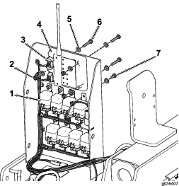
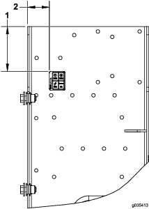
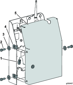
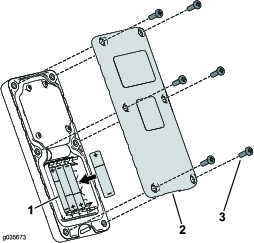
  1. Remove the 6 screws from the back of the remote and remove the cover (Figure 32).

    Note: If possible, leave the rubber seal and steel gasket in the channel when removing the cover and batteries.

    g035673
  2. Remove the discharged batteries and dispose of them in accordance with local regulations.

  3. Install each new battery into a terminal cradle observing proper polarity.

    Note: The controller cannot function when the batteries are installed improperly.

  4. If you accidentally removed the rubber seal and the steel gasket, replace them carefully into the channel in the handheld remote.

  5. Install the cover and secure it with the 6 screws removed previously (Figure 32) and torque them to 1.5 to 1.7 N∙m (13 to 15 in-lb).

    Note: Do not overtighten the screws.

Close section
Close section

Troubleshooting

ConditionPossible CausesCorrective Action
The diagnostic light on the sweeper does not illuminate when pressing a remote button.

There is frequency interference.

Associate the remote control to the base unit. Refer to Associating the Remote Control and the Base Unit

Checking Fault Codes

If the diagnostic light indicates that there is a system fault, check the fault codes to determine what is wrong with the machine. Refer to Entering Diagnostic Mode.

Close section

Entering Diagnostic Mode

  1. Turn the key to the RUN position.

  2. Disconnect the wire harness from the traction unit to the sweeper to disable power to the sweeper.

  3. Remove the compartment cover.

  4. Pull the tethered cap off the 2 diagnostic, shunt connectors (Figure 33A).

  5. Connect the diagnostic, shunt connectors together (Figure 33B).

    g030474
  6. Connect the wire harness from the traction unit to the sweeper to enable power to the sweeper.

  7. Count the number of flashes to determine the fault code, then consult the following table:

    Note: If there are multiple faults, both faults flash, then a long pause, then the flash sequences repeat.

Close section

Decoding the Fault Codes

CodeLED Flash PatternBehaviorDetails
Machine Specific Faults
11Blink once, pause, blink once, long pause, then repeatLost communication with BASE.Connector not plugged in; locate the loose or disconnected wire harness connector and connect it.
Something wrong in the wiring; contact your Toro Distributor.
BASE is bad; contact your Toro Distributor.
12Blink once, pause, blink twice, long pause, then repeatVersion incompatibility of the BASE and/or HH.Wrong software (install the correct software from TORODIAG); contact your Toro Distributor.
13Blink once, pause, blink 3 times, long pause, then repeatWrong HH (not implemented on RevA).Wrong product association (i.e. trying to update software on a MH-400 with a ProPass handheld)
Close section

Resetting the Fault Codes

After solving the problem, disconnect and reconnect the diagnostic connectors. The diagnostic light flashes continuously once per second.

Close section

Exiting Diagnostic Mode

  1. Turn the key to the RUN position.

  2. Disconnect the wire harness from the traction unit to the sweeper to disable power to the sweeper.

  3. Disconnect the diagnostic, shunt connectors.

  4. Push the tethered cap onto the 2 diagnostic, shunt connectors.

  5. Connect the wire harness from the sweeper to the traction unit to enable power to the sweeper.

  6. Install the compartment cover.

Close section
Close section