
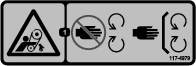
 , which means: Caution, Warning, or Danger—personal
safety instruction. Failure to comply with the instruction may result
in personal injury or death.
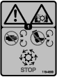
, which means: Caution, Warning, or Danger—personal
safety instruction. Failure to comply with the instruction may result
in personal injury or death.

Maintenance
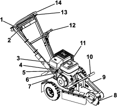
Note: Determine the left and right sides of the machine from the normal operating position.
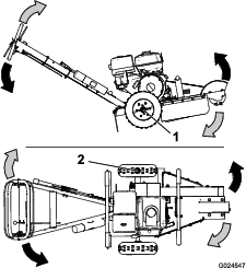
Important: You can tip the machine backward or on its side to clean or service it, but no longer than 2 minutes. If you hold the machine in this position for too long, fuel can drain into the crankcase and damage the engine. Should this happen, perform an extra oil change on the engine. Then turn the engine over a few revolutions with the starter handle before starting the engine again.
Caution
If you leave the key in the key switch, someone could accidently start the engine and seriously injure you or other bystanders.
Remove the key from the key switch and disconnect the wires from the spark plugs before you do any maintenance. Set the wires aside so that they do not accidentally contact the spark plugs.
Recommended Maintenance Schedule(s)
| Maintenance Service Interval | Maintenance Procedure |
|---|---|
| After the first 20 hours |
|
| Before each use or daily |
|
| Every 50 hours |
|
| Every 100 hours |
|
| Every 300 hours |
|
| Every 600 hours |
|
| Yearly or before storage |
|
Important: Refer to your engine owner’s manual for additional maintenance procedures.
Lubrication
Greasing the Machine
| Maintenance Service Interval | Maintenance Procedure |
|---|---|
| Before each use or daily |
|
Grease Type: General-purpose grease.
-
Park the machine on a level surface and engage the parking brake.
-
Shut off the engine, remove the key, and allow the engine to cool.
-
Clean the grease fittings with a rag.
-
Connect a grease gun to each fitting.
-
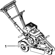
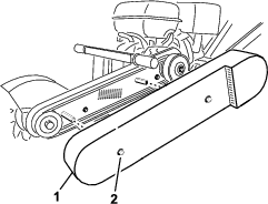
Lubricate the 2 fittings, 1 on each cutting-wheel bearing.
-
Pump grease into the fittings until grease begins to ooze out of the bearings (approximately 3 pumps).
Important: Pump grease in slowly and carefully to prevent damage to the bearing seals.
-
Wipe up any excess grease.
Engine Maintenance
Servicing the Air Cleaner
| Maintenance Service Interval | Maintenance Procedure |
|---|---|
| Before each use or daily |
|
| Every 50 hours |
|
| Every 600 hours |
|
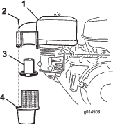
The cyclone air filter collects the largest contaminant particles, which collect in the container. When you can see a layer of dirt at the bottom of the container, clean the cyclone housing, air channels, and air-intake screen.
Servicing the Cyclone Housing
-
Park the machine on a level surface and engage the parking brake.
-
Shut off the engine and remove the key.
-
Remove the 3 screws holding the cyclone housing to the air-cleaner cover.
-
Remove the housing with the air-intake screen and remove the air channels.
-
Clean the components with water, detergent, and a brush then dry the components carefully.
-
Place the air channels in the cyclone housing.
-
Insert cyclone housing into position and make sure it fits in the upper portion.
Important: Do not use force; align it in place before fitting the screws.
Servicing the Air-Cleaner Elements
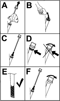
Removing the Foam and Paper Elements
-
Park the machine on a level surface and engage the parking brake.
-
Shut off the engine and remove the key.
-
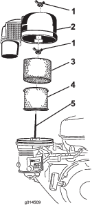
Remove the wing nut and lift off the air-cleaner cover with the air-filter cowling (Figure 15).
-
Remove the foam element (Figure 15).
-
Remove the wing nut on top of the paper element and remove the paper element (Figure 15).
Servicing the Foam Air-Cleaner Element
-
Wash the foam element using a mild detergent and water.
-
Squeeze it dry with a clean cloth.
-
Soak it with new engine oil.
-
Gently squeeze out excess oil from the element in an absorbent cloth.
Servicing the Paper Air-Cleaner Element
-
Clean the paper element by tapping it gently to remove dust. If it is very dirty, replace the paper element with a new one (Figure 15).
-
Inspect the element for tears, an oily film, or damage to the rubber seal.
-
Replace the paper element if it is damaged.
Important: Do not clean the paper filter.
Installing the Foam and Paper Elements
-
Mount the paper element in the air-cleaner housing and secure it with the wing nut.
-
Position the foam element over the paper element.
-
Install the air-cleaner cover and secure it with the wing nut.
Servicing the Engine Oil
| Maintenance Service Interval | Maintenance Procedure |
|---|---|
| After the first 20 hours |
|
| Before each use or daily |
|
| Every 100 hours |
|
| Yearly or before storage |
|
Note: Change the oil more frequently when the operating conditions are extremely dusty or sandy.
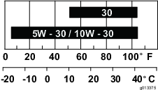
Oil Type: Detergent oil with an API service of SJ or higher.
Crankcase Capacity: 1.1 L (1.2 US qt)
Viscosity: Refer to the figure below.
Checking the Engine-Oil Level
-
Park the machine on a level surface and engage the parking brake.
-
Shut off the engine and remove the key.
-
Check the engine-oil level as shown in Figure 17.
Changing the Engine Oil
Note: Dispose of the used oil at a recycling center.
-
Start the engine and let it run for 5 minutes.
Note: This warms the oil so that it drains better.
-
Park the machine on a level surface and engage the parking brake.
-
Shut off the engine and remove the key.
-
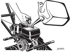
Change the oil as shown in (Figure 18).
-
Slowly pour approximately 80% of the specified oil into the filler tube and slowly add the additional oil to bring it to the Full mark (Figure 19).
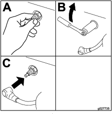
Servicing the Spark Plug
| Maintenance Service Interval | Maintenance Procedure |
|---|---|
| Every 100 hours |
|
| Every 300 hours |
|
Ensure that the air gap between the center and side electrodes is correct before installing the spark plug. Use a spark plug wrench for removing and installing the spark plug and a gapping tool/feeler gauge to check and adjust the air gap. Install a new spark plug if necessary.
Type: BPR6ES (NKG) or equivalent
Air Gap: 0.70 to 0.80 mm (0.28 to 0.031 inch)
Removing the Spark Plug
-
Park the machine on a level surface and engage the parking brake.
-
Shut off the engine and remove the key.
-
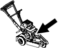
Locate and remove the spark plugs (Figure 20).

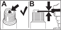
Checking the Spark Plug
Important: Do not clean the spark plug(s). Always replace the spark plug(s) when it has: a black coating, worn electrodes, an oily film, or cracks.
If you see light brown or gray on the insulator, the engine is operating properly. A black coating on the insulator usually means the air cleaner is dirty.
Set the gap to 0.70 to 0.80 mm (0.28 to 0.031 inch).
Installing the Spark Plug
Tighten the spark plug(s) to 27 N∙m (20 ft-lb).
Fuel System Maintenance
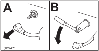
Cleaning the Sediment Cup
| Maintenance Service Interval | Maintenance Procedure |
|---|---|
| Every 100 hours |
|
| Yearly or before storage |
|
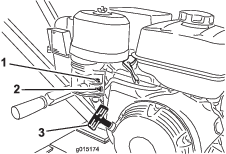
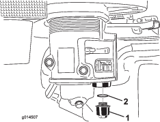
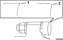
Underneath the fuel valve is a sediment cup to catch dirt in the fuel.
-
Park the machine on a level surface and engage the parking brake.
-
Shut off the engine and remove the key.
-
Move the fuel valve to the OFF position, all the way to the left.
-
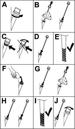
Unscrew the sediment cup (Figure 23).
-
Clean the reservoir and the O-ring using a cleaning solvent and dry carefully.
Note: Make sure not to misplace the O-ring.
-
Place the O-ring in the groove of the cup and replace the sediment cup.
-
Turn the fuel valve to the ON position, all the way to the right, and check for leaks.
Note: If it leaks, replace the O-ring.
Brake Maintenance
Adjusting the Parking Brake
-
Park the machine on a level surface and engage the parking brake.
-
Shut off the engine and remove the key.
-
Loosen the set screw on side of brake lever knob. Turn the knob clockwise to tighten the brake; turn the knob counter-clockwise to loosen the brake.
Note: The left wheel should lock completely when the brake is engaged.
-
Tighten the set screw.
Belt Maintenance
Adjusting the Drive-Belt Tension
| Maintenance Service Interval | Maintenance Procedure |
|---|---|
| Before each use or daily |
|
Note: Inspect the drive belt through the slot on top of the belt cover. Adjust as required.
-
Park the machine on a level surface and engage the parking brake.
-
Shut off the engine and remove the key.
-
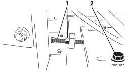
Loosen the 2 bolts securing the belt guard to machine until you can remove the belt guard (Figure 24).
Note: The bolts and washers will remain attached to the belt guard.
-
Remove the belt guard (Figure 24).
-
Loosen the 4 engine-plate mounting bolts and the 4 bolts securing the rear of the belt guard to the engine.
-
Loosen the belt-tension bolt and jam nut. Slide the engine toward the flywheel housing to loosen the belt (Figure 25).
-
Adjust the drive-belt tension by tightening tension bolt and jam nut against the engine mounting plate, pushing the engine rearward.
-
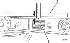
Lay a straightedge across the clutch and flywheel pulleys. Tighten the belt-tension bolt so there is 10 mm (0.40 inch) of flex in the belt when pushing down with 6.8 kg (15 lb) force at mid-span (when re-tensioning a belt in use), or with 8 kg (18 lb) force when installing a new belt (Figure 26).
-
Ensure that the pulleys are aligned and the engine is parallel with the frame (not angled toward the side), then tighten the 4 engine-plate mounting bolts and the 4 bolts securing the rear of the belt guard to the engine.
-
Install the belt guard and tighten the bolts.
Replacing the Drive Belt
| Maintenance Service Interval | Maintenance Procedure |
|---|---|
| Every 100 hours |
|
Note: Replace the belt if it shows any signs of wear, cracks, glazing, or damage.
-
Park the machine on a level surface and engage the parking brake.
-
Shut off the engine and remove the key.
-
Loosen the bolts securing the belt guard to machine until you can remove the belt guard..
-
Remove the belt guard (Figure 24).
-
Loosen the 4 engine-plate mounting bolts and the 4 bolts securing the rear of the belt guard to the engine.
-
Loosen the belt tension bolt and jam nut and slide the engine toward the flywheel housing to loosen the belt (Figure 25).
-
Replace drive belt.
-
Adjust tension of new belt to 8 kg (18 lb) force and 10 mm (0.40 inch) belt deflection at mid-span.
-
Tighten the 4 engine-plate mounting bolts and the 4 bolts securing the rear of the belt guard to the engine.
-
Install the belt guard and secure it with the previously removed washers and bolts.
Grinder Maintenance
Replacing the Teeth
| Maintenance Service Interval | Maintenance Procedure |
|---|---|
| Before each use or daily |
|
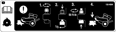
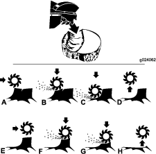
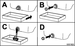
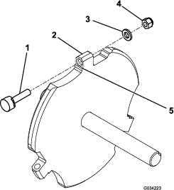
Due to the high amount of wear placed on the teeth, you need to rotate and replace them periodically (Figure 27). Before you rotate or replace them, inspect each tooth holder on the wheel, including the flat lands that prevent the teeth from rotating. If the tooth holder is damaged, replace the wheel. Torque the nuts 68 N∙m (50 ft-lb) for any teeth that you are not rotating or replacing.
Each tooth is indexed with 3 positions so you can rotate it twice, exposing a new sharp edge before replacing the tooth. To rotate a tooth, loosen the nut securing the tooth (Figure 28). Push the tooth forward and rotate it 1/3 of a turn, bringing an unused edge to the outside. Torque the nut securing the tooth to 68 N∙m (50 ft-lb).
To replace a tooth, remove the nut securing the tooth, then install a new tooth, washer, and nut in the same position (Figure 28). Torque the nut securing the tooth to 68 N∙m (50 ft-lb).
Cleaning
Removing Debris from the Machine
| Maintenance Service Interval | Maintenance Procedure |
|---|---|
| Before each use or daily |
|
Regular cleaning and washing increases the life span of the machine. Clean the machine directly after use, before the dirt hardens.
Before cleaning, check that the fuel-tank cap is properly in place to avoid getting water in the tank.
Use care when using a high-pressure sprayer, because it can damage warning decals, instruction signs, and the engine
Important: Lubricate the cutting wheel bearings after cleaning.