


Maintenance
Recommended Maintenance Schedule(s)
| Maintenance Service Interval | Maintenance Procedure |
|---|---|
| After the first 2 operating hours |
|
| After the first 8 operating hours |
|
| After the first 10 operating hours |
|
| After the first 50 operating hours |
|
| Before each use or daily |
|
| Every 25 hours |
|
| Every 50 hours |
|
| Every 100 hours |
|
| Every 200 hours |
|
| Every 400 hours |
|
| Every 600 hours |
|
| Every 800 hours |
|
| Every 1,000 hours |
|
Note: Determine the left and right sides of the machine from the normal operating position.
Danger
Only qualified and authorized personnel should maintain, repair, adjust, or inspect the machine.
Avoid fire hazards and have fire protection equipment present in the work area. Do not use an open flame to check the level or leakage of fuel, battery electrolyte, or coolant. Do not use open pans of fuel or flammable cleaning fluids for cleaning parts.
Caution
If you leave the key in the key switch, someone could accidently start the engine and seriously injure you or other bystanders.
Remove the key from the key switch before you do any maintenance.
Operating in Adverse Conditions
Important: If the machine is subjected to any of the conditions listed below, perform maintenance twice as frequently:
-
Desert operation
-
Cold-climate operation below 0°C (32°F)
-
Trailer towing
-
Frequent operation on dusty roads
-
Construction work
-
After extended operation in mud, sand, water, or similar dirty conditions, have your brakes inspected and cleaned as soon as possible. This prevents any abrasive material from causing excessive wear.
Pre-Maintenance Procedures
Many of the subjects covered in this maintenance section require raising and lowering the bed. To prevent serious injury or death, take the following precautions.
Warning
A raised bed full of material without the proper safety support rod may lower unexpectedly. Working under an unsupported raised bed may cause injury to you or others.
-
Before servicing or making adjustments to the machine, park the machine on a level surface, engage the parking brake, shut off the engine, and remove the key.
-
Remove any load material from the bed or other attachment and insert the safety support on a fully extended cylinder rod before working under a raised bed.
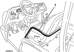
Using the Bed Support
Important: Always install or remove the bed support from the outside of the bed.
-
Raise the bed until the lift cylinders are fully extended.
-
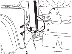
Remove the bed support from the storage brackets on the back of the ROPS panel (Figure 32).
-
Push the bed support onto the cylinder rod, ensuring that the support end tabs rest on the end of the cylinder barrel, and on the cylinder-rod end (Figure 33).
-
Remove the bed support from the cylinder and insert it into the brackets on the back of the ROPS panel.
Important: Do not try to lower the bed with the bed-safety support on the cylinder.
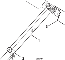
Removing the Full Bed
-
Start the engine, engage the hydraulic-lift lever, and lower the bed until the cylinders are loose in the slots.
-
Release the lift lever and shut off the engine.
-
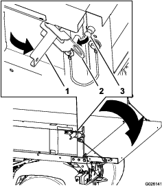
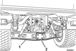
Remove the lynch pins from the outer ends of the cylinder-rod clevis pins (Figure 34).
-
Remove the clevis pins securing the cylinder-rod ends to the bed-mounting plates by pushing the pins toward the inside (Figure 34).
-
Remove the lynch pins and clevis pins securing the pivot brackets to the frame channels (Figure 34).
-
Lift the bed off the machine.
Important: The full bed weighs approximately 148 kg (325 lb), so do not try to install or remove it by yourself.Use an overhead hoist or get the help of 2 or 3 other people.
-
Store the cylinders in the storage clips.
-
Engage the hydraulic-lift-lock lever on the machine to prevent accidental extension of the lift cylinders.
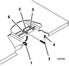
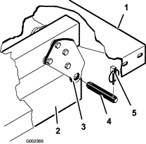
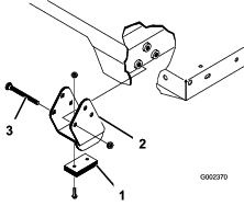
Installing the Full Bed
Note: If you install the bed sides on the flat bed, it is easier to install them before installing the bed on the machine.
Note: Ensure that the rear pivot plates are bolted to the bed frame/channel so that the lower end angles to the rear (Figure 35).
Important: The full bed weighs approximately 148 kg (325 lb), so do not try to install or remove it by yourself.Use an overhead hoist or get the help of 2 or 3 other people.
Note: Ensure that the spacer brackets and wear blocks (Figure 36) are installed with the carriage-bolt heads positioned inside the machine.
-
Ensure that the lift cylinders are fully retracted.
-
Carefully set the bed onto the machine frame, aligning the rear bed pivot-plate holes with the holes in the rear frame channel and install 2 clevis pins and lynch pins (Figure 36).
-
With the bed lowered, secure each cylinder rod end, to the appropriate slots in the bed-mounting plates with a clevis pin and lynch pin.
-
Insert the clevis pin from outside of the bed with the lynch pin toward the outside (Figure 36).
Note: The rear slots are for a full bed installation and front slots are for a 2/3 bed installation.
Note: The engine may need to be started to extend or retract the cylinders for alignment with the holes.
Note: The unused slot can be plugged with a bolt and nut to prevent assembly errors.
-
Start the engine and engage the hydraulic-lift lever to raise the bed.
-
Release the lift lever and turn off the engine.
-
Install the bed-safety support to prevent accidental lowering of the bed; refer to Using the Bed Support.
-
Install the lynch pins to the inside ends of the clevis pins.
Note: If the automatic-tailgate release has been installed on the bed, ensure that the front dump link rod has been placed on the inside of the left side clevis pin before you install the lynch pin.
Raising the Machine
Danger
A machine on a jack may be unstable and slip off the jack, injuring anyone beneath it.
-
Do not start the machine while the machine is on a jack.
-
Always remove the key from the key switch before getting off of the machine.
-
Block the tires when the machine is on a jack.
-
Do not start the engine while the machine is on a jack, because the engine vibration or wheel movement could cause the machine to slip off the jack.
-
Do not work under the machine without jack stands supporting it. The machine could slip off a jack, injuring anyone beneath it.
-
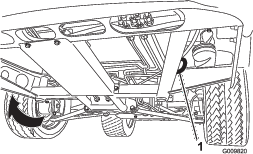
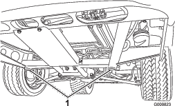
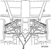
When jacking up the front of the machine, always place a wooden block (or similar material) between the jack and the machine frame.
-
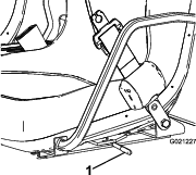
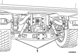
The jacking point at the front of the machine is under the front center frame support (Figure 37) and at the rear it is under the axle (Figure 38).
Removing the Hood
-
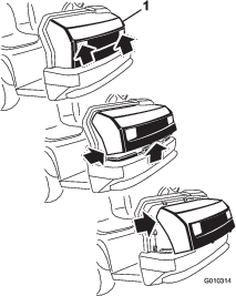
While grasping the hood in the headlight openings, lift up the hood to release the lower mounting tabs from the frame slots (Figure 39).
-
Pivot the bottom of the hood upward until the top mounting tabs can be pulled from the frame slots (Figure 39).
-
Pivot the top of the hood forward, and unplug the wire connectors from the head lights (Figure 39).
-
Remove the hood.
Installing the Hood
-
Connect the lights.
-
Insert the top mounting tabs into the frame slots.
-
Insert the lower mounting tabs into the frame slots.
-
Ensure that the hood is fully engaged in the top, sides and bottom grooves.
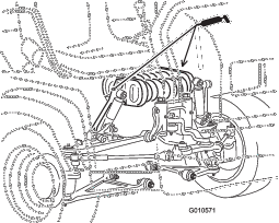
Lubrication
Greasing the Bearings and Bushings
The machine has grease fittings that must be lubricated regularly with No. 2 lithium grease.
The grease fitting locations and quantities are as follows:
-
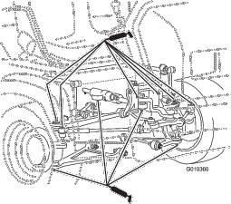
Ball joints (4), tie rods (2), pivot mounts (2) and steering cylinder (2) as shown in Figure 40
-
Spring tower (2) as shown in Figure 41
-
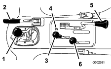
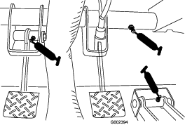
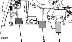
Clutch (1), accelerator (1), and brake (1) as shown in Figure 42
-
U-joint (18) and 4-wheel-drive shaft (3) as shown in Figure 43
Important: When greasing the drive shaft universal shaft bearing crosses, pump grease until it comes out of all 4 cups at each cross.
-
Wipe each grease fitting clean so foreign matter cannot be forced into the bearing or bushing.
-
Pump grease into each bearing or bushing.
-
Wipe off excess grease.
Engine Maintenance
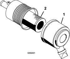
Servicing the Air Cleaner
Inspect the air cleaner and hoses periodically to maintain maximum engine protection and to ensure maximum service life. Check the air-cleaner body for damage, which could possibly cause an air leak. Replace a damaged air-cleaner body.
Inspect and change the air-cleaner filter as described in the following procedure:
-
Release the latches on the air cleaner and pull the air-cleaner cover off the air-cleaner body (Figure 44).
-
Squeeze the dust cap sides to open it and knock the dust out.
-
Gently slide the filter out of the air-cleaner body (Figure 44).
Note: Avoid knocking the filter into the side of the body.
Note: Do not attempt to clean the filter.
-
Inspect the new filter for damage by looking into the filter while shining a bright light on the outside of the filter.
Note: Holes in the filter appear as bright spots.
Note: Inspect the element for tears, an oily film, or damage to the rubber seal. If the filter is damaged, do not use it.
Note: To prevent engine damage, always operate the engine with the air filter and cover installed.
Note: Take special care to keep particulates from dropping into the clean areas of the air-filter housing.
-
Carefully slide the filter over the body tube (Figure 44).
Note: Ensure that it is fully seated by pushing on the outer rim of the filter while installing it.
-
Install the air-cleaner cover with the side facing up, and secure the latches (Figure 44).
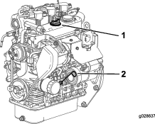
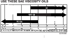
Changing the Engine Oil and Filter
Engine-oil quantity: 3.2 L (3.4 US qt) (with a filter)
Engine-oil type: Detergent engine oil API SJ or higher
Engine-oil viscosity: 10W-30; Choose an engine-oil viscosity according to the ambient-air temperature to the table in Figure 45.
-
Raise the bed (if equipped), and place the safety support on the extended-lift cylinder to hold up the bed.
-
Remove the drain plug and let the oil flow into a drain pan (Figure 46).
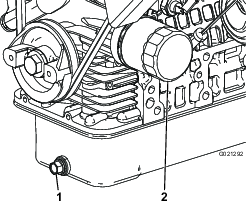
-
When the oil stops, install the drain plug.
-
Remove the oil filter (Figure 46).
-
Apply a light coat of clean oil to the new filter seal before screwing it on.
-
Screw the filter on until the gasket contacts the mounting plate, then tighten the filter 1/2 to 2/3 of a turn.
Note: Do not overtighten.
-
Add the specified oil to the crankcase.
Fuel System Maintenance
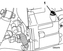
Checking the Fuel Lines and Connections
Inspect the fuel lines and connections for deterioration, damage, or loose connections.
Close sectionServicing the Fuel Filter/Water Separator
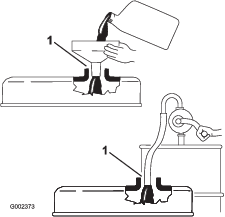
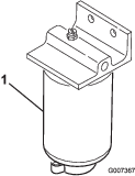
Draining the Fuel Filter/Water Separator
-
Place a clean container under the fuel filter (Figure 47).
-
Loosen the drain plug on the bottom of the filter canister.
-
Tighten the drain plug on the bottom of the filter canister.
Changing the Fuel Filter
-
Drain the water from the water separator; refer to Draining the Fuel Filter/Water Separator.
-
Clean the area where the filter mounts (Figure 47).
-
Remove the filter and clean the mounting surface.
-
Lubricate the gasket on the filter with clean oil.
-
Install the filter by hand until the gasket contacts mounting surface, then rotate it an additional 1/2 turn.
-
Tighten the drain plug on the bottom of the filter canister.
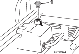
Electrical System Maintenance
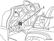
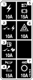
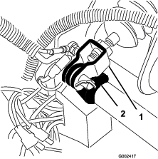
Servicing the Fuses
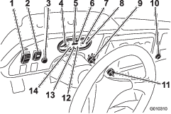
The fuses for the electrical system are located under the center of the dash panel (Figure 48 and Figure 49).
Jump-Starting the Machine
Warning
Jump-starting the machine can be dangerous, causing personal injury or damage to the electrical components in the machine.
-
Never jump-start with a voltage source greater than 15 VDC; this damages the electrical system.
-
Never attempt to jump-start a discharged battery that is frozen. It could rupture or explode during jump-starting.
-
Observe all battery warnings while jump-starting the machine.
-
Be sure that your machine is not touching the jump-start machine.
-
Connecting cables to the wrong post could result in personal injury and/or damage to the electrical system.
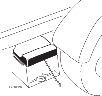
-
Squeeze the battery cover to release the tabs from the battery base, and remove the battery cover from the battery base (Figure 50).
-
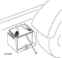
Connect a jumper cable between the positive posts of the 2 batteries (Figure 51).
Note: The positive post may be identified by a + sign on top of the battery cover.
-
Connect 1 end of the other jumper cable to the negative terminal of the battery in the other machine.
Note: The negative terminal has “NEG on the battery cover.
Note: Do not connect the other end of the jumper cable to the negative post of the discharged battery. Connect the jumper cable to the engine or frame. Do not connect the jumper cable to the fuel system.
-
Start the engine in the machine providing the jump-start.
Note: Let it run for a few minutes, then start the engine.
-
Remove the negative jumper cable first from the engine, then the battery in the other machine.
-
Install the battery cover to the battery base.
Servicing the Battery
Warning
CALIFORNIA
Proposition 65 Warning
Battery posts, terminals, and related accessories contain lead and lead compounds, chemicals known to the State of California to cause cancer and reproductive harm. Wash hands after handling.
Danger
Battery electrolyte contains sulfuric acid, which is a deadly poison and causes severe burns.
-
Do not drink electrolyte and avoid contact with skin, eyes or clothing. Wear safety glasses to shield your eyes and rubber gloves to protect your hands.
-
Fill the battery where clean water is always available for flushing the skin.
-
Keep the battery-electrolyte level properly maintained.
-
Keep the top of the battery clean by washing it periodically with a brush dipped in ammonia or bicarbonate of soda solution. Flush the top surface with water after cleaning. Do not remove the fill cap while cleaning.
-
Ensure that the battery cables are kept tight on the terminals to provide good electrical contact.
-
If corrosion occurs at terminals, remove the battery cover, disconnect the cables (negative (–) cable first), and scrape the clamps and terminals separately. Connect the cables (positive (+) cable first) and coat the terminals with petroleum jelly.
-
Maintain cell electrolyte level with distilled or demineralized water. Do not fill the cells above the bottom of the fill ring inside each cell.
-
If you store the machine in a location where temperatures are extremely high, the battery runs down more rapidly than if the machine is stored in a location where temperatures are cool.
Drive System Maintenance
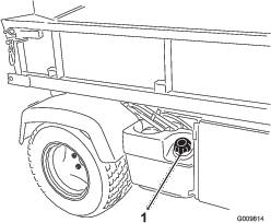
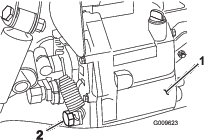
Changing the Front Differential Oil
Differential-oil specification: Mobil 424 hydraulic fluid
-
Park the machine on a level surface, engage the parking brake, shut off the engine, and remove the key.
-
Clean the area around the drain plug on the side of the differential (Figure 52).
-
Place a drain pan under the drain plug.
-
Remove the drain plug and let the oil flow into the drain pan.
-
Install and tighten the plug when the oil stops draining.
-
Clean the area around the fill/check plug on the bottom of the differential.
-
Remove the fill/check plug and add specified oil until the oil level is up to the hole.
-
Install the fill/check plug.
Inspecting the Constant-Velocity Boot
Inspect the constant-velocity boot for cracks, holes, or a loose clamp. Contact your Authorized Toro Distributor for repair if you find any damage.
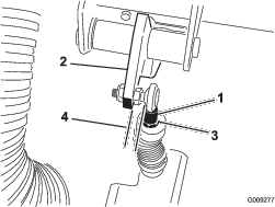
Close sectionAdjusting the Shift Cables
-
Move the shift lever to the NEUTRAL position.
-
Remove the clevis pins securing the shift cables to the transaxle-shift arms (Figure 53).
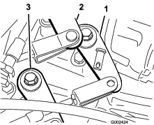
-
Loosen the clevis jam nuts and adjust each clevis, so that the cable free play is equal forward and backward relative to the hole in the transaxle-shift arm (with the transaxle lever free play taken up in the same direction).
-
Install the clevis pins and tighten the jam nuts when finished.
Adjusting the High-to-Low Cable
-
Remove the clevis pin securing the high-to-low cable to the transaxle (Figure 53).
-
Loosen the clevis jam nut and adjust the clevis so that the clevis hole aligns with the hole in the transaxle bracket.
-
Install the clevis pin and tighten the jam nut when finished.
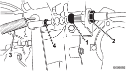
Adjusting Differential-Lock Cable
-
Move the differential-lock lever to the OFF position.
-
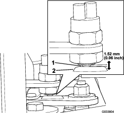
Loosen the jam nuts securing the differential-lock cable to the bracket on the transaxle (Figure 54).
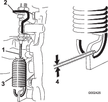
-
Adjust the jam nuts to obtain a 0.25 to 1.5 mm (0.01 to 0.06 inch) gap between the spring hook and the OD of the hole in the transaxle lever.
-
Tighten the jam nuts when finished.
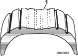
Inspecting the Tires
The air pressure in the front tires should be 220 kPa (32 psi) and the rear tires should be 124 kPa (18 psi).
Operating accidents, such as hitting curbs, can damage a tire or rim and also disrupt wheel alignment, so inspect the tire condition after an accident.
Important: Check the tire pressure frequently to ensure proper inflation. If the tires are not inflated to the correct pressure, the tires will wear prematurely and may cause 4-wheel drive to bind.
Figure 55 is an example of tire wear caused by under-inflation.

Figure 56 is an example of tire wear caused by over inflation.
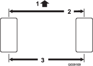
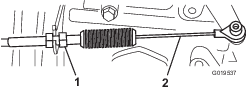
Checking the Front-Wheel Alignment
-
Make sure that the tires are facing straight ahead.
-
Measure the center-to-center distance (at axle height) at the front and rear of the steering tires (Figure 57).
Note: The measurement must be within 0 3 mm (0 0.12 inch) at the front of the tire then at the rear of the tire. Rotate the tire 90° and check the measurement.
Important: Check the measurements at consistent locations on the tire. The machine should be on a flat surface with the tires facing straight ahead.
-
Adjust the center-to-center distance as follows:
-
Loosen the jam nut at the center of the tie rod (Figure 58).
-
Rotate the tie rod to move the front of the tire inward or outward to achieve the center to center distances from front to back.
-
Tighten the tie rod jam nut when the adjustment is correct.
-
Check to ensure that the tires turn an equal amount to the right and to the left.
Note: If the tires do not turn equally, refer to the Service Manual for the adjustment procedure.
-
Cooling System Maintenance
Removing Debris from the Cooling System
-
Turn the engine off and clean the engine area thoroughly of all debris.
-
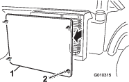
Unlatch and remove the radiator screen from the front of the radiator (Figure 59).
-
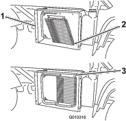
If so equipped, rotate the latches and pivot the oil cooler away from the radiator (Figure 60).
-
Clean the radiator, oil cooler, and screen thoroughly with compressed air.
Note: Blow debris away from the radiator. Do not use water to clean external surfaces of the radiator.
-
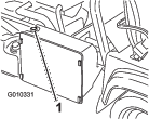
Install the cooler and screen to the radiator.
Changing the Engine Coolant
Coolant type: 50/50 mixture of water and permanent ethylene-glycol antifreeze
Note: Multiple cycles of the following procedure may be required to properly flush and change the engine coolant.
-
Park the machine on a level surface.
-
Raise the bed (if so equipped) and place the safety support on the extended-lift cylinder to hold up the bed.
Caution
If the engine has been running, the pressurized, hot coolant can escape and cause burns.
-
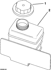
Do not open the reserve tank cap when the engine is running.
-
Allow engine to cool at least 15 minutes or until the reserve tank cap is cool enough to touch without burning your hand.
-
Use a rag when opening the reserve tank cap, and open the cap slowly to allow steam to escape.
-
-
Remove the radiator cap.
-
Remove the reserve-tank cap (Figure 62).
-
Disconnect the lower radiator hose and allow coolant to flow into a drain pan.
-
When coolant stops, connect the lower radiator hose.
-
Remove the coolant-drain plug from the engine and allow coolant to flow into a drain pan.
-
When coolant stops, install the drain plug.
-
Slowly fill the radiator with a 50/50 mixture of water and permanent ethylene-glycol antifreeze.
-
Install the radiator cap.
-
Fill the reservoir tank to the bottom of the filler neck.
-
Start the engine and allow it to idle.
-
As air escapes, fill the reservoir to the bottom of the filler neck.
Note: Do not allow the engine to heat up to the running temperature.
-
Install the reserve-tank cap.
-
Run the machine until it reaches the operating temperature.
-
Turn off the machine and allow it to cool.
-
Check the coolant level again, and replenish it, if required.
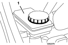
Brake Maintenance
Adjusting the Parking Brake
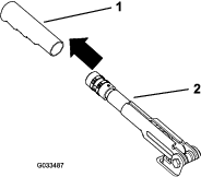
-
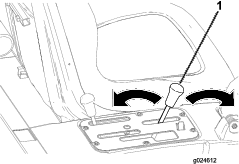
Remove the rubber grip from the parking-brake lever (Figure 63).
-
Loosen the set screw securing the knob to the parking-brake lever (Figure 64).
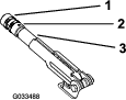
-
Rotate the knob until a force of 20 to 22 kg (45 to 50 lb) is required to actuate the lever.
-
Tighten the set screw when finished.
Note: If no adjustment is left at the handle, loosen the handle to the middle of the adjustment and adjust the cable at the rear, then repeat step 3.
-
Install the rubber grip onto the parking-brake lever.
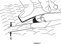
Adjusting the Brake Pedal
Note: Remove the font hood to ease the adjustment procedure.
-
Remove the cotter pin and clevis pin securing the master cylinder yoke to the brake-pedal pivot (Figure 65).
-
Lift up on the brake pedal (Figure 66) until it contacts the frame.
-
Loosen the jam nuts securing the yoke to the master cylinder shaft (Figure 66).
-
Adjust the yoke until its holes align with the hole in the brake-pedal pivot.
-
Secure the yoke to the pedal pivot with the clevis pin and cotter pin.
-
Tighten the jam nuts securing the yoke to the master cylinder shaft.
Note: The brake master cylinder must relieve pressure when properly adjusted.
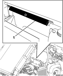
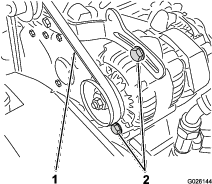
Belt Maintenance
Adjusting the Alternator Belt
-
Raise the bed (if equipped) and position the safety support on the extended-lift cylinder to hold up the bed.
-
Check the tension by pressing the belt at mid span between the crankshaft and alternator pulleys with 10 kg (22 lb) of force (Figure 67).
Note: A new belt should deflect 8 to 12 mm (0.3 to 0.5 inch).
Note: A used belt should deflect 10 to 14 mm (0.4 to 0.55 inch). If the deflection is incorrect, proceed to the next step. If correct, continue operation.
-
To adjust the belt tension, complete the following:
Controls System Maintenance
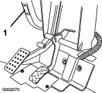
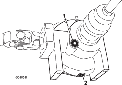
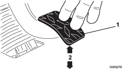
Adjusting the Accelerator Pedal
-
Park the machine on a level surface, engage the parking brake, shut off the engine, and remove the key.
-
Adjust the ball joint on the accelerator cable (Figure 68) to allow 2.54 to 6.35 mm (0.100 to 0.250 inch) of clearance between the accelerator-pedal arm and the top of the diamond tread floor plate (Figure 69), when a 11.3 kg (25 lb) force is applied to the center of the pedal.
Note: The engine must not be running and the return spring must be attached.
-
Tighten the locknut (Figure 68).
Important: The maximum high-idle speed is 3,650 rpm. Do not adjust the high-idle stop.
Close sectionAdjusting the Clutch Pedal
Note: You can adjust the clutch-pedal cable at the bell housing or at the clutch-pedal pivot. You can remove the front hood to ease the access to the pedal pivot.
-
Loosen the jam nuts securing the clutch cable to the bracket on the bell housing (Figure 70).
Note: You may remove and rotate the ball joint if additional adjustment is required.
-
Disconnect the return spring from the clutch lever.
-
Adjust the jam nuts or ball joint until the rear edge of the clutch pedal is 9.2 to 9.8 cm (3-5/8 to 3-7/8 inches) from the top of the floor plate diamond pattern, when an 1.8 kg (4 lb) force is applied to the pedal (Figure 71).
Note: Force is applied so the clutch release bearing lightly contacts the pressure plate fingers.
-
Tighten the jam nuts after the adjustment has been attained.
-
Check the 9.2 to 9.8 cm (3-5/8 to 3-7/8 inches) dimension after the jam nuts have been tightened to ensure proper adjustment.
Note: Adjust again if it is necessary.
-
Connect the return spring to the clutch lever.
Important: Ensure that the rod end is positioned squarely on the ball, not twisted, and remains parallel to the clutch pedal after the jam nut is tightened (Figure 72).
Note: The clutch free play should never be less than 19 mm (3/4 inch).
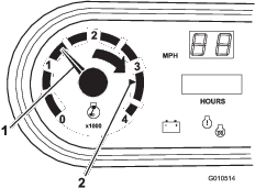
Converting the Speedometer
You can convert the speedometer from mph to km/h or km/h to mph.
-
Park the machine on a level surface, engage the parking brake, shut off the engine, and remove the key.
-
Remove the hood; refer to Removing the Hood.
-
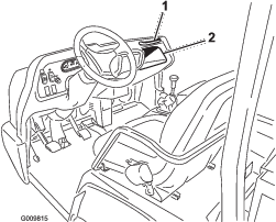
Locate the 2 loose wires next to the speedometer.
-
Remove the connector plug from the harness wire and connect the wires together.
Note: The speedometer switches to km/h or mph.
-
Install the hood.
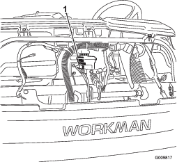
Hydraulic System Maintenance
Changing the Hydraulic Fluid and Cleaning the Strainer
Hydraulic-fluid capacity: 7 L (7.5 US qt)
Hydraulic-fluid type: Dexron III ATF
-
Park the machine on a level surface, engage the parking brake, shut off the engine, and remove the key.
-
Remove the drain plug from the side of the reservoir, and let the hydraulic fluid flow into a drain pan (Figure 73).
-
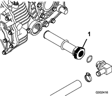
Note the orientation of the hydraulic hose and 90° fitting connected to the strainer on the side of the reservoir (Figure 74).
-
Remove the hydraulic hose and 90° fitting.
-
Remove the strainer and clean it by back flushing it with a clean de-greaser.
Note: Allow it to air dry before installing.
-
Install the strainer.
-
Install the hydraulic hose and 90° fitting to the strainer in the same orientation.
-
Install and tighten the drain plug.
-
Fill the reservoir with approximately 7 L (7.5 US qt) of the specified hydraulic fluid; refer to Checking the Transaxle/Hydraulic-Fluid Level.
-
Start the engine and operate the machine to fill the hydraulic system.
-
Check the hydraulic-fluid level and replenish it, if required.
Important: Use only the hydraulic fluid specified. Other fluids could damage the system.
Close sectionReplacing the Hydraulic Filter
Important: Use of any other filter may void the warranty on some components.
-
Park the machine on a level surface, engage the parking brake, shut off the engine, and remove the key.
-
Clean the area around the filter-mounting area.
-
Place a drain pan under the filter and remove the filter (Figure 75).

-
Lubricate the gasket on the new filter.
-
Ensure that the filter mounting area is clean.
-
Screw the filter on until the gasket contacts the mounting plate, and tighten the filter 1/2 turn.
-
Start the engine and let it run for about 2 minutes to purge air from the system.
-
Shut off the engine and check the hydraulic-fluid level and for leaks.
Changing the High-Flow Hydraulic Fluid and Filter
Hydraulic-fluid capacity: approximately 15 L (4 US gallons)
Hydraulic-fluid type:Toro Premium All Season Hydraulic Fluid (Available in 5 gallon pails or 55 gallon drums. See parts catalog or Toro distributor for part numbers.)
Alternate fluids: If the Toro fluid is not available, another conventional petroleum–based fluid may be used provided it meets the following material properties and industry specifications. Consult with your lubricant distributor to identify a satisfactory product.
Note: Toro will not assume responsibility for damage caused by improper substitutions, so use only products from reputable manufacturers who will stand behind their recommendation.
High Viscosity Index/Low Pour Point Antiwear Hydraulic Fluid, ISO VG 46
Material Properties:
-
Viscosity—ASTM D445 cSt @ 40C: 44 to 48/cSt @ 100C: 7.9 to 8.5
-
Viscosity Index, ASTM D2270—140 to 152
-
Pour Point, ASTM D97— -35F to -46F
-
FZG, Fail stage—11 or better
-
Water content (new fluid)—500 ppm (maximum)
Industry Specifications:
Vickers I-286-S, Vickers M-2950-S, Denison HF-0, Vickers 35 VQ 25 (Eaton ATS373-C)
Note: Many hydraulic fluids are almost colorless, making it difficult to spot leaks. A red dye additive for the hydraulic system fluid is available in 20 ml (0.67 oz) bottles. A bottle is sufficient for 15 to 22 L (4 to 6 US gallons) of hydraulic fluid. Order Part No. 44-2500 from your authorized Toro distributor.
Note: If the fluid becomes contaminated, contact your local Toro distributor because the system must be flushed. Contaminated fluid may look milky or black when compared to clean fluid. The service interval may need to be increased if using multiple attachments as the fluid may become contaminated quicker with the mixing of different hydraulic fluids.
-
Clean the area around the high-flow-filter mounting area (Figure 75).
-
Place a drain pan under the filter and remove the filter.
Note: If the fluid is not going to be drained, disconnect and plug the hydraulic line going to the filter.
-
Lubricate the new filter-sealing gasket and hand turn the filter onto the filter head until the gasket contacts the filter head. Then tighten it 3/4 turn further. The filter should now be sealed.
-
Fill the hydraulic reservoir with approximately 15 L (4 US gallons) of hydraulic fluid.
-
Start the machine and run it at idle for about 2 minutes to circulate the fluid and remove any air trapped in the system.
-
Stop the machine and check the fluid level.
-
Verify the fluid level.
-
Dispose of the fluid properly.
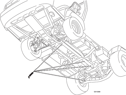
Raising the Cargo Box in an Emergency
The cargo box can be raised in an emergency without starting the engine by cranking starter or by jumping the hydraulic system.
Raising the Cargo Box using the Starter
Crank the starter while holding the lift lever in the Raise position. Run the starter for 10 seconds, then wait 60 seconds before engaging the starter again. If the engine does not crank, you must remove the load and box (attachment) to service the engine or transaxle.
Close sectionRaising the Cargo Box by Jumping the Hydraulic System
Caution
A raised bed full of material without the proper safety support rod may lower unexpectedly. Working under an unsupported raised bed may cause injury to you or others.
-
Before servicing or making adjustments to the machine, park the machine on a level surface, engage the parking brake, shut off the engine, and remove the key.
-
Remove any load material from the bed or other attachment and insert the safety support on a fully extended cylinder rod before working under a raised bed.
You will need 2 hydraulic hoses, each with a male and female quick coupler, that fit the machine couplers, to perform this operation.
-
Back another machine up to the rear of the disabled machine.
Important: The machine hydraulic system uses Dexron III ATF. To avoid system contamination, make sure that the machine used to jump the hydraulic system uses an equivalent fluid.
-
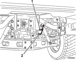
On both machine, disconnect the 2 quick-coupler hoses from the hoses secured to the coupler bracket (Figure 76).
-
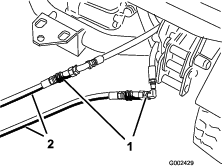
On the disabled machine, connect the 2 jumper hoses to the hoses that were disconnected (Figure 77).
-
Cap the unused fittings.
-
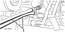
On the other machine, connect the 2 hoses to the coupler still in the coupler bracket (connect the top hose to the top coupler and the bottom hose to the bottom coupler) (Figure 78).
-
Cap the unused fittings.
-
Keep all bystanders away from the machines.
-
Start the second machine and move the lift lever to the raise position, which raises the disabled cargo box.
-
Move the hydraulic-lift lever to the NEUTRAL position, and engage the lift-lever lock.
-
Install the bed support onto the extended lift cylinder; refer to Using the Bed Support.
Note: With both the machine turned off, move the lift lever back and forth to remove the system pressure and ease the disconnection of the quick couplers.
-
After completing the operation, remove the jumper hoses and connect the hydraulic hoses to both machines.
Important: Check the hydraulic fluid levels, in both machines, before resuming operation.
Washing the Machine
Wash the machine as needed. Use water alone or with a mild detergent. You may use a rag when washing the machine.
Important: Do not use power-washing equipment to wash the machine. Power-washing equipment may damage the electrical system, loosen important decals, or wash away necessary grease at friction points. Avoid excessive use of water near the control panel, engine, and battery.
Important: Do not wash the machine with the engine running. Washing the machine with the engine running may result in internal engine damage.
Close section