Setup

Preparing the Machine

  1. Park the machine on a level surface.

    g196985
  2. Engage the parking brake.

  3. Lower the cutting units.

  4. Shut off the engine and remove the key.

Close section

Installing the Kit

Installing the Rear Lights

  1. Raise the operator platform and disconnect the battery; refer to the traction unit Operator’s Manual.

  2. Assemble the left and right rear lamp assemblies (Figure 2).

  3. Route the wires through the side rails of the chassis and connect them to the 3-pin sockets on the existing wire harness. Secure the right side with a cable tie.

    Note: The reflector must be at the top of each assembly

    g206686
Close section

Installing the Number-Plate Assembly

  1. Drill 4 holes (5 mm diameter) in the frame; refer to Figure 2 and Figure 3. Use the number plate as a template.

  2. Secure the bracket using the self-tapping screws (Figure 2).

  3. Connect the wire to the lamp.

  4. Secure the wire to the upright section of the frame using the 3 cable ties (1 cable tie to secure at the top of the wire assembly from the lamp, a second cable tie to the center securing wire behind the bracket and the third cable tie to retain the wire and sleeve at the bottom of the upright).

  5. Locate the 3-pin socket through the aperture in the rear chassis and connect the number plate wire.

Note: You can remove the rear guard plate for access.

g206694
Close section

Installing the Wire Harness

  1. With the operator platform still in the raised position, route the wiring loom by feeding the longest section underneath the control panel below the lift levers, following the existing loom.

  2. Connect the 4-pin plug to the existing loom socket.

  3. Route the lighting loom through the front seat support bracket and to the front of the machine, branching left and right before passing through the front chassis.

  4. Using the existing hose ties, secure the loom into position.

Close section

Installing the Switches

  1. Remove the blanking plugs from the instrument panel in order to locate the switches (Figure 5).

  2. Feed the plug and black wire through the cut out in the control panel behind the handbrake and fit the hazard warning switch. Push the switch down to locate.

  3. Connect the brown/purple wire to the second fuse holder from the outside. Fit the 10A fuse (Figure 6).

  4. Connect the red/purple wire to the third fuse holder from the outside. Fit the 15A fuse (Figure 6).

  5. Feed the plugs and wires through the cut-outs in the top of the control panel and fit the indicator, dip/main and light switches.

  6. Fit the lenses to the switches supplied with the kit.

  7. Feed the flasher relay base under the existing relays. Slot into place beside the existing relays and retain with a bolt, washers, and nut. Fit the flasher relay.

  8. Retain lighting loom to the existing loom under the control panel using 2 small cable ties.

  9. Ensure that the front light wires are correctly routed as follows:

    • Green/red: right indicator

    • Green/white: left indicator

  10. Secure the loom to the roller plate brace using the large cable ties (Figure 4).

    g206687
  11. Feed the plugs from the front lights through to the roller plate and connect to the loom.

  12. Secure together using the small cable ties to ensure that the wires and plugs remain in place, and do not interfere with the movement of the front arms.

  13. Ensure that all wiring is routed carefully away from sharp edges to prevent damage.

  14. Proceed to the fitting instructions for the front lights.

g206688
g206692
Close section

Installing the Front Lights

Kit 02845 is required for the T4240 so that the front lights can be clearly seen with the cutting units raised.

To install the fitting kit 02845 with the lighting kit 02844 to a T4240 traction unit, follow these instructions.

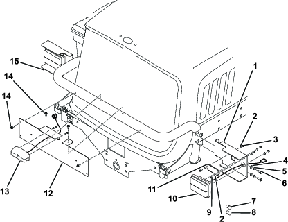
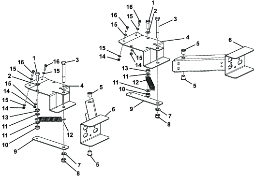
  1. Assemble the front light arm assemblies as shown in Figure 7.

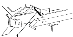
  2. Fit the front light arm assemblies to the machine and check that they spring forward freely when pushed back and released.

  3. Use the cable ties to secure the sidelight cables to the brace and the front arm. Take care to ensure that the wire is not strained when the front light arm is articulated through its full range of travel.

  4. Connect the positive (+) battery lead first and then connect the negative (-) battery lead.

  5. Close the operator platform and secure in place with the platform latching mechanism. Refer to the traction unit Operator’s Manual.

g206691
Close section
Close section

Checking the Operation of the Lights

  1. With the ignition on, rock the indicator switch left to operate the front and rear left orange indicator lights. The indicator warning light on the switch will also flash (Figure 5 and Figure 6).

  2. With the ignition on, rock the indicator switch right to operate the front and rear right orange indicator lights. The indicator warning light on the switch will also flash.

  3. With the ignition off or on, rock the light switch backward to switch on the 2 rear red position lights, the 2 front white position lights and number plate light. The warning light on the switch will also light up.

  4. With the ignition and light switch on, rock the headlight switch forward to dipped headlights.

  5. Rock the headlight switch backward for main-beam headlights. The main-beam warning light on the switch will also light up.

  6. With the ignition off or on, rock the hazard switch backward to operate and flash all 4 orange indicator lights simultaneously. The hazard warning lights on the switch will also flash.

If the lights operate incorrectly, check the wiring connections against the diagram, reconnect the wires as necessary, and check the operation of the lights again.

  1. In order to comply with the road vehicle lighting regulations adjust the front dipped beam headlights so that the horizontal part of the cutoff of the beam is inclined downward.

  2. To set the front dipped-beam headlights, slacken the nut located under the headlight, adjust as required, and tighten the nut.

Close section
Close section

Maintenance

Replacing a Bulb

Replace all worn or damaged parts with genuine Toro parts.

Ensure that all lights are working on a regular basis.

  1. Remove the lens cover; refer to Figure 8.

  2. Replace the bulb.

  3. Install the lens cover.

  4. Adjust the lights to ensure that they comply with local road legislation.

g206685
Close section
Close section