Maintenance
-
Keep the lenses clean by wiping them with a damp cloth. Do not use solvent-based cleaners.
-
Replace all light bulbs as needed. Use replacement bulbs that have the proper voltage and wattage rating; refer to the old bulb for details.
Determine the left and right sides of the machine from the normal operating position.
CALIFORNIA
Proposition 65 Warning
Move the machine to level ground and engage the parking brake.
Lower the cutting deck to the ground.
Shut off the engine and remove the key.
Unlatch and raise the engine cover, and secure it in the raised position with the prop rod.
Disconnect the negative (-) battery cable from the battery.
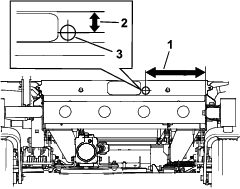
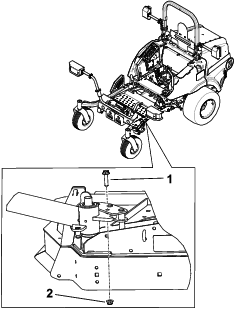
Drill the hole as shown in Figure 1.
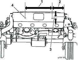
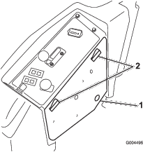
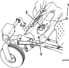
Drill the holes as shown in Figure 2.
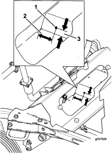
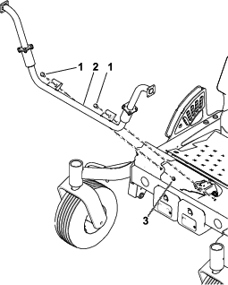
Drill the holes for the horn as shown in Figure 3.
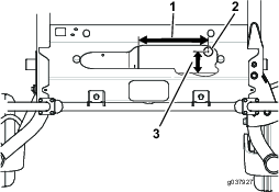
Drill the holes as shown in Figure 4.
Parts needed for this procedure:
| Hazard warning switch | 1 |
Unlatch the side cover of the control panel (Figure 5) and set it aside.
Locate and remove the knockout plug located towards the front of the control panel under the decal (Figure 6).
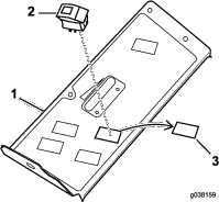
Note: Position the lens on the hazard switch away from the operator.
Insert the light switch as shown in Figure 6.
Parts needed for this procedure:
| Left rear light | 1 |
| Right rear light | 1 |
| U-bolt | 4 |
| Flange nut (3/8 inch) | 8 |
| Light plate | 1 |
| Center rear light | 1 |
| Bolt (#10 x 7/8 inches) | 2 |
| Bolt (1/4 x 3/4 inch) | 2 |
| Flange nut (#10) | 4 |
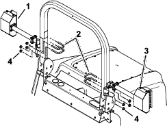
Install the left and right rear lights with 4 U-bolts and 4 flange nuts (3/8 inch) (Figure 7). Ensure that you do not cover the decal.
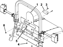
Install the light plate and center rear light (Figure 8).
Note: You may need an extra person to hold the light plate as you secure it to the machine.
Parts needed for this procedure:
| Headlight-mount assembly | 1 |
| Flange nut (3/8 inch) | 2 |
| Bolt (3/8 x 1 inch) | 2 |
Install the headlight-mount assembly to the front of the machine with 2 bolts (3/8 x 1 inch) and 2 flange nuts (3/8 inch); refer to Figure 9.
Parts needed for this procedure:
| Locknut (1/4 inch) | 8 |
| Right headlight assembly | 1 |
| Leftt headlight assembly | 1 |
| Bolt (1/4 x 3/4 inch) | 8 |
| Optional headlight extension | 2 |
Remove the shields from the headlights (Figure 11).
Note: The optional headlight extensions are for the 183 cm (72 inch) and 254 cm (100 inch) mower decks only (Figure 10).
If needed, install the headlight extension with 4 bolts (1/4 x 3/4 inch) and 4 locknuts (1/4 inch); refer to Figure 10.
Install the headlight to the extension or the headlight mount assembly with 4 bolts (1/4 x 3/4 inch) and 4 locknuts (1/4 inch); refer to Figure 10.
Install the front light electrical connectors (Figure 11).
Install the shields to the headlights (Figure 11).
Parts needed for this procedure:
| Flange bolt (3/8 x 1-1/2 inches) | 1 |
| Flange nut (3/8 inch) | 1 |
Important: This procedure is only for 254 cm (100 inch) mower decks.
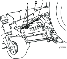
Secure the caster-fork latch as shown in Figure 12.
Parts needed for this procedure:
| Lever | 1 |
Remove the existing left handle and retain the washers and bolts.
Install the new handle with the existing washers and bolts (Figure 13).

Parts needed for this procedure:
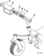
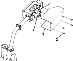
| Horn | 1 |
| Carriage bolt (5/16 x 5/8 inch) | 1 |
| Flange nut (5/16 inch) | 1 |
Install the horn as shown in Figure 14.
Parts needed for this procedure:
| Wiring harness | 1 |
| 20A fuse | 1 |
| Relay | 1 |
| Flasher module | 1 |
Note: Do not attach the black (negative) lead until the whole kit is installed.
Thread the wiring harness branch with the flasher relay up into the side cover, where the main harness enters the panel (Figure 14).
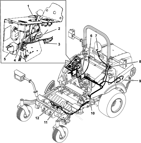
Use the blade connectors under the control panel as follows:
Note: Use only 1 of the blade connectors shown in Figure 15.
If the Auxiliary Power Unit (model 30382) is installed, connect the correct blade connector to the open blade on the auxiliary power module.
If the Auxiliary Power Unit (model 30382) is not installed, connect the correct blade connector that fits to the existing pink wire.
Use Figure 15 to route the wiring harness into the machine.
Use the magnetic holders shown in Figure 16 to secure the wire harness.
Parts needed for this procedure:
| 20 kmp decal | 3 |
| Serial plate | 1 |
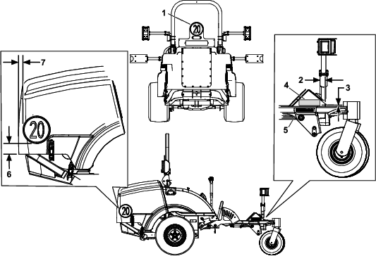
Install the 20 kmp decals as shown in Figure 17.
Install the serial plate as shown in Figure 17.
Stamp the date into the side of the metal frame in the area shown in Figure 17.
Attach the negative battery cable and the black (negative) lead to the battery.
Latch the engine cover.
Test all the functions of the kit.
The hazard warning switch operates the hazard warning lights and will work whether the ignition is switched to the ON or OFF position (Figure 18).

Press the side of the rocker switch with the hazard warning symbol to operate the hazard warning lights.
Press the other side of the rocker switch to turn off the hazard warning lights.
The direction-indicator switch operates the right and left direction indicator lights when the ignition is switched to the ON position (Figure 19).
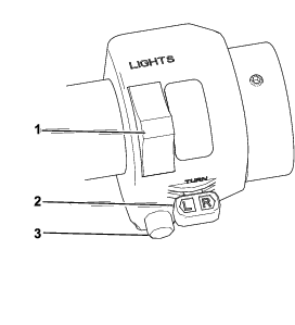
Press the left side of the indicator switch to turn on the left direction-indicator lights.
Press the right side of the indicator switch to the central position to turn off the left direction-indicator lights.
Press the right side of the indicator switch to turn on the right direction-indicator lights.
Press the left side of the indicator switch to the central position to turn off the right direction-indicator lights.
The headlamp and dipped beam switch operates the headlamps only when the ignition is switched to On (Figure 19).
Push the switch forward to turn on the headlamp.
Push the switch backward to turn on the dipped-beam headlamp.
Push the horn button to operate the horn.
Keep the lenses clean by wiping them with a damp cloth. Do not use solvent-based cleaners.
Replace all light bulbs as needed. Use replacement bulbs that have the proper voltage and wattage rating; refer to the old bulb for details.