CALIFORNIA
Proposition 65 Warning
Park the machine on a level surface.
Engage the parking brake.
Lower the hopper.
Shut off the engine.
Remove the cowl.
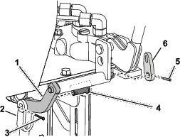
Remove the 2 cotter pins, U-link, and clevis pin (3/16 x 1 inch) from the handle assembly (Figure 1). Retain the clevis pin, but discard the 2 cotter pins and U-link.
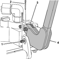
Remove and discard the handle assembly (Figure 1).
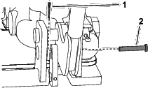
Remove and retain the flange bolt (5/16 x 1 inch), nut (5/16 inch), clevis pin (3/8 x 1-3/32 inch) and cotter pin (3/4 inch) as shown in Figure 2.
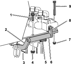
Remove and discard the bolt (1/4 x 2-1/4 inches), nut (1/4 inch), pivot, shaft guide (including the 2 bearings), and lever plate (Figure 2).
Parts needed for this procedure:
| Pivot | 1 |
| Lever plate | 1 |
| Lever assembly | 1 |
| Shaft guide | 1 |
| Pin | 1 |
| Clevis pin | 1 |
| Cotter pin (1/2 inch) | 1 |
| Bearing | 2 |
| Bolt (1/4 x 2-1/4 inches) | 1 |
| Cotter pin (1 inch) | 1 |
| Nut (1/4 inch) | 1 |
Install the shaft guide using the flange bolt (5/16 x 1 inch) and nut (5/16 inch) that you removed previously, and the kit bolt (1/4 x 2-1/4 inches) and nut (1/4 inch) as shown in Figure 3.
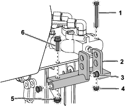
Install the bearings into the shaft guide (Figure 3).
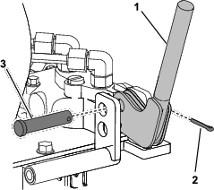
Install the kit through the shaft guide and handle assembly, and secure it using the cotter pin (1 inch) as shown in Figure 4.
Slide the pivot through the shaft guide, and secure it to the yoke using the clevis pin (3/8 x 1-3/32 inch) and cotter pin (3/4 inch) that you removed previously (Figure 5).
Secure the other end of the pivot to the lever plate using a pin (Figure 5).
Secure the handle to the lever plate using a cotter pin (1/2 inch) and the clevis pin (3/16 x 1 inch) that you removed previously (Figure 6).
Install the cowl.