Introduction

This kit is designed to add the light components required for on-road travel. It is a dedicated attachment for a turf spray application vehicle and is intended to be used by professional, hired operators in commercial applications.

Note: Determine the left and right sides of the machine from the normal operating position.

Read these instructions carefully to learn how to operate and maintain your product properly. The information in this manual can help you and others avoid injury and product damage. Although Toro designs and produces safe products, you are responsible for operating the product properly and safely.

You may contact Toro directly at www.Toro.com for product and accessory information, help finding a dealer, or to register your product.

Whenever you need service, genuine Toro parts, or additional information, contact an Authorized Service Dealer or Toro Customer Service and have the model and serial numbers of your product ready. Figure 1 illustrates the location of the model and serial numbers on the product.

g207494

Warning

CALIFORNIA

Proposition 65 Warning

Close section

Setup

Preparing to Install the Kit

Warning

Incorrect battery cable routing could damage the sprayer and cables causing sparks. Sparks can cause the battery gasses to explode, resulting in personal injury.

  • Always disconnect the negative (black) battery cable before disconnecting the positive (red) cable.

  • Always connect the positive (red) battery cable before connecting the negative (black) cable.

Warning

Battery terminals or metal tools could short against metal sprayer components causing sparks. Sparks can cause the battery gasses to explode, resulting in personal injury.

  • When removing or installing the battery, do not allow the battery terminals to touch any metal parts of the sprayer.

  • Do not allow metal tools to short between the battery terminals and metal parts of the sprayer.

  • Always keep the battery strap in place to protect and secure the battery.

  1. Move the machine to a level surface, fully press in the brake pedal, and set the parking-brake pedal; refer to the Operator’s Manual.

  2. Rotate the key switch to the Off position, and remove the key; refer to the Operator’s Manual.

  3. Remove the battery cover and disconnect the negative (black—ground) cable from the battery post (Figure 2).

    g207342
  4. Disconnect the positive (red) cable from the battery post (Figure 2).

Close section

Removing the Forward Heat Shield and Undercarriage Shroud

Removing the Forward Heat Shield

  1. Engage the parking brake, shut off the spray pump, shut off the engine, and remove the key.

  2. Raise the front and back of the machine and support it with jack stands; refer to the Operator’s Manual.

  3. Remove the 6 hex-head bolts and 6 washers that secure the front, forward heat shield to the chassis and remove the shield (Figure 3).

    Note: Retain the bolts, washers, and heat shield for installation in Installing the Forward-Heat Shield.

    g028168
Close section

Removing the Undercarriage Shroud

g032041
  1. Remove the following hardware that secures the rear of the undercarriage shroud to the chassis of the machine (Figure 5):

    • 2016 machines—7 flange-head bolts (5/16 x 7/8 inch) and 7 washers (5/16 inch)

    • 2017 and later machines—5 flange-head bolts (5/16 x 7/8 inch) and 5 washers (5/16 inch)

    Note: Retain the flange-head bolts and washers for installation in step 5 of Removing the Undercarriage Shroud.

    g208653
  2. Remove the 4 flange locknuts (5/16 inch) from the bolts and carriage bolts that secure the support straps of the undercarriage shroud to the engine-mount brackets of the machine (Figure 6).

    Note: Do not remove the bolts from the machine. Retain the flange locknuts for installation in step 3 of Installing the Undercarriage Shroud.

    g032043
  3. Lift the support straps over the bolts that secure the undercarriage shroud to the engine-mount brackets.

  4. Remove the undercarriage shroud from the machine (Figure 5 and Figure 6).

Close section
Close section

Assembling the Worklight and Wire Harness

Parts needed for this procedure:

Wire Harness1
Grommet1
Worklight mount2
Support channel1
Flange-head bolt (3/8 x 2-1/4 inches)4
Spacer4
Flange locknut (3/8 inch)4
Worklight2

Assembling the Grommet onto the Wire Harness

g207897
  1. Align the 6-socket connector for the of the 112 cm (44 inches) wire harness branch through the grommet and move the grommet toward the 112 cm (44 inches) wire harness branch (Figure 9).

    g207895
  2. Align the 6-socket connector for the of the 99 cm (39 inches) wire harness branch through the grommet (Figure 8).

  3. Position the grommet as shown in Figure 9.

    g207891
Close section

Assembling the Wire Harness to the Worklight Support

  1. Assemble the 2 worklight mounts onto the 112 cm (44 inches) wire harness branch and the 99 cm (39 inches) wire harness branch as shown in Figure 10.

    g207890
  2. Align the holes in the support channel, spacer, and worklight mount as shown in Figure 11.

    g207904g207896
  3. Assemble the support channel to the worklight mount (Figure 11) with the 4 flange-head bolts (3/8 x 2-1/4 inches), 4 spacers, and 2 flange locknuts (3/8 inch).

    Note: Assemble the locknut onto the flange-head bolt at the outboard position.

  4. Assemble the support channel to the worklight mount (Figure 11) with the 4 flange-head bolts (3/8 x 2-1/4 inches), 4 spacers, and 2 flange locknuts (3/8 inch).

    Note: Assemble the locknut onto the flange-head bolt at the outboard position.

  5. Tighten the flange-head bolt and flange locknut to remove the gap between the worklight mount, spacer, and support channel.

  6. Insert the push-in fastener of the wire harness into the hole in the end of the worklight mount as shown in Figure 12.

    g208157
  7. Repeat steps 2 through 6 for the worklight mount at the other end of the support channel (Figure 11).

Close section

Installing Worklights to the Support

  1. Align the left and right worklight assemblies with the amber lenses outward as shown in Figure 13.

    g207936
  2. Assemble a serrated shell and a spherical joint onto the stud of a worklight (Figure 14).

    g207892
  3. Assemble the worklight into the hole in the flange of the worklight mount (Figure 14) with a serrated shell, spherical joint, and locknut (10 mm), and tighten the lamp by hand.

    Note: Tighten the worklight enough to maintain its position, but allow the operator to align the light if needed.

  4. Repeat steps 2 and 3 for the worklight at the other head-lamp mount.

  5. Plug the 6-socket connectors labeled and 6-socket connector ( into the 6-pin connectors of the worklights (Figure 15).

    g207894
Close section

Installing the Worklight Assembly to the Machine

  1. Assemble the worklight mount and support channel to the frame of the floor plate with 2 flange locknuts as shown in Figure 14.

    g207893
  2. Torque the 4 flange-head bolts and 4 flange locknuts to 37 to 45 N∙m (27 to 33 ft-lb).

Close section
Close section

Installing the Wire Harness for the Switches

Parts needed for this procedure:

Flange-head bolt (1/4 x 3/4 inch)1
Flasher module (CE)1
Flange locknut (1/4 inch)1
Cable tie2
Horn switch1
Jam nut (5/8 inch)1
Knurled nut (5/8 inch)1
Button1
Switch—rocker (on-off-on)1
Switch—rocker (illuminated)1
Turn-signal switch1
Hose clamp1

Routing the Wire Harness to the Dash Panel

g208167
  1. Route the 108 cm (42-1/2 inches) branch of the kit wire harness up along the front wire harness of the machine and through the grommet in the floor plate (Figure 18).

    g208202
  2. Continue routing the branch of the kit wire harness up and under the dash panel of the machine (Figure 19).

    g208203
  3. From inside the storage compartment, insert a flange-head bolt (1/4 x 3/4 inch) though the hole in the inboard wall of the compartment (Figure 20).

    g208200
  4. Assemble the CE flasher module to the flange-head bolt with a flange locknut (1/4 inch), and tighten by hand (Figure 21).

    g208199
  5. Plug the 6-socket connector of the kit wire harness into the CE flasher module (Figure 22).

    g208201
  6. Plug the 6-pin connector of the machine wire harness into the 6-pin connector of the kit wire harness labeled (Figure 22).

  7. Secure the 108 cm (42-1/2 inches) branch of the kit wire harness to the front wire harness of the machine with 2 cable ties as shown in Figure 23.

g208204
Close section

Installing the Horn Switch

  1. Remove the round knockout from the dash panel as shown in Figure 24.

    g208262
  2. Access the 3 connectors at the end of the 108 cm (42-1/2 inches) branch of the kit wire harness (Figure 25).

    g208263
  3. Thread the jam nut (5/8 inch) onto the threads of the horn switch (Figure 25).

  4. Plug the 2 spade terminals of the horn switch into the 2-socket connector of the 108 cm (42-1/2 inches) branch of the kit wire harness (Figure 25).

  5. From under the dash panel, align the body of the horn switch through the hole (Figure 26) in the dash panel that you made in step 1.

    g208261
  6. Assemble the horn switch to dash panel with the knurled nut (5/8 inch), and tighten the nut by hand (Figure 27).

    g208260
  7. Thread the button onto the threads of the horn switch (Figure 27).

Close section

Replacing the Light Switch

  1. Remove the light switch from dash panel (Figure 28).

    g208264
  2. Remove the 8-socket connector labeled from the headlight switch (Figure 28).

    Note: Discard the headlight switch.

  3. Align the socket terminal at the end of the 108 cm (42-1/2 inches) branch of the kit wire harness labeled to the back of the 8-socket connector for the headlight switch (Figure 29).

    g208275
  4. Insert the terminal into socket 1 of the 8-socket connector for the headlight switch as shown in Figure 30.

    g208276
  5. Plug the rocker switch from the kit into the 8-socket connector for the headlight switch (Figure 31).

    g208277
  6. Insert the rocker switch into the opening in the dash panel until the switch snaps securely into the dash (Figure 31).

Close section

Installing the Flasher Switch

  1. Remove the rectangular knockout from the dash panel as shown in Figure 32.

    g208339
  2. Align the 8-socket connector for the hazard switch through the opening in the dash panel (Figure 33) that you made in step 1.

    g208338
  3. Plug the illuminated-rocker switch into the 8-socket connector for the hazard switch (Figure 33).

  4. Insert the rocker switch into the opening in the dash panel until the switch snaps securely into the dash (Figure 33).

Close section

Installing the Turn-Signal Switch

  1. Assemble the turn-signal switch to the steering valve with the hose clamp as shown in Figure 34, and tighten the clamp by hand.

    g208383
  2. Plug the 8-socket connector of the 108 cm (42-1/2 inches) branch of the kit wire harness for the turn signal into the 8-pin connector of the wire harness from the turn-signal switch (Figure 35).

    g208384
Close section
Close section

Installing the Horn

Parts needed for this procedure:

Horn assembly1
Flange-head bolt (3/8 x 1 inch)1
Flange locknut (3/8 inch)1
  1. Align the hole in the bracket of the horn assembly with the hole 10 mm (3/8 inch) in the floor-plate angle adjacent to the steering hydraulic hoses (Figure 36).

    g207491g207490
  2. Assemble the bracket of the horn assembly to the floor-plate angle (Figure 36) with a flange-head bolt (3/8 x 1 inch) and flange locknut (3/8 inch).

  3. Torque the bolt and nut to 37 to 45 N∙m (27 to 33 ft-lb).

Close section

Installing the Wire Harness to the Chassis

Parts needed for this procedure:

Cable tie5

Routing the Wire Harness Under the Floor Plate

g208166
  1. Route the 71 cm (28 inches) wire harness branch, 89 cm (35 inches) wire harness branch, and 452 cm (178 inches) wire harness trunk through the R-clamp that secures the steering hoses, located below the floor plate and forward of the front axle (Figure 38).

    g208159
  2. Plug the 2 terminals of the wire harness labeled onto the 2 spade-electrical connectors of the horn (Figure 39).

    g208158
  3. Route the wire harness branches and trunk through the R-clamp l below the floor plate and behind the front axle (Figure 40).

    g208160
Close section

Routing the Wire Harness Along the Frame

  1. Route the wire harness branches and trunk up and along the rear wire harness of the machine and between the frame of the machine and the engine (Figure 41).

    g208161
  2. Secure the wire harness of the kit to the rear wire harness of the machine with a cable tie as shown in Figure 41.

  3. Continue routing the wire harness branches and trunk rearward along the rear wire harness of the machine as shown in Figure 42.

    g208162
  4. Secure the wire harness of the kit to the rear wire harness of the machine with 2 cable ties as shown in Figure 42.

Close section

Routing the Wire Harness to the Center Spray Section

  1. Route the wire harness branches and trunk up at the center spray section as shown in Figure 43 and Figure 44.

    g208163
    g208165
  2. Secure the wire harness of the kit to the rear wire harness of the machine with a cable tie as shown in Figure 44.

  3. Route the wire harness of the kit to the center spray section (Figure 45) as follows:

    • The wire harness trunk along the wires to the lift-cylinder manifold.

    • The 89 cm (35 inches) wire harness branch (with the electrical connector labeled ) toward the left end of the center spray section.

    • The 71 cm (28 inches) wire harness branch (with the electrical connector labeled ) toward the right end of the center spray section.

    g208164
Close section
Close section

Installing the Speed Signs and License Plate Brackets

Parts needed for this procedure:

Speed decal3
Speed sign1
Flange-head bolts (5/16 x 3/4 inch)2
Flange locknuts (5/16 inch)2

Installing the Speed Decal on the Sprayer Tank

g207686
  1. At the left side of the tank, align a piece of masking tape 56 cm (22 inches) across the bottom of the Toro Multi Pro 5800 decal and rearward as shown in Figure 47.

    g207684
  2. Measure 11 cm (4-1/4 inches) from the right edge of the Toro Multi Pro 5800 decal and mark the tank with a pencil Figure 47.

  3. Remove the backing from a speed decal and align the decal to the mark that you made in step 1 and the top edge of the masking tape (Figure 47).

  4. Apply to decal to the tank and remove the masking tape (Figure 47).

  5. At the right side of the tank, align a piece of masking tape 48 cm (19 inches) across the top of the Toro Multi Pro 5800 decal and forward as shown in Figure 48.

    g207685
  6. Measure 28 mm (1-1/8 inches) from the bottom edge of the masking tape and mark the tank with a pencil (Figure 48).

  7. Measure 21 mm (13/16 inch) from the left edge of the Toro Multi Pro 5800 decal and mark the tank with a pencil (Figure 48).

  8. Remove the backing from a speed decal and align the decal to the marks (Figure 48) that you made in steps 6 and 7.

  9. Apply to decal to the tank and remove the masking tape (Figure 48).

Close section

Installing the Speed Sign on the Center-Boom Section

  1. Remove the backing from a speed decal (Figure 49).

    g209224
  2. Align the decal to the speed sign as shown in Figure 49.

  3. Press the decal onto the surface of the tank from the top down while removing air bubbles as you apply the decal.

  4. Remove the 2 flange-head bolts (5/16 x 1 inch) and 2 flange locknuts (5/16 inch) that secure the bracket for the lift-cylinder manifold bracket to the lift-cylinder mount (Figure 51).

    Note: Discard the bolts and nuts.

    g207640
  5. Align the holes in the speed-sign bracket, lift-cylinder manifold bracket, and lift-cylinder mount (Figure 51).

    g207639
  6. Assemble the speed sign bracket to the cylinder manifold bracket and lift-cylinder mount (Figure 51) with 2 flange-head bolts (5/16 x 1 inch) with the 2 flange locknuts (5/16 inch).

  7. Torque the bolts and nuts to 1978 to 2542 N∙cm (175 to 225 in-lb).

Close section

Installing the License Plate Brackets

  1. Assemble the license-plate bracket to the support bracket with the 2 flange-head bolts (5/16 x 3/4 inch) and 2 flange locknuts (5/16 inch) as shown in Figure 52.

    g207637
  2. Torque the bolts and nuts to 1978 to 2542 N∙cm (175 to 225 in-lb).

  3. Align the holes in the support bracket with the holes in the truss of the center-spray section (Figure 53).

    g207638
  4. Assemble the support bracket to the truss of the center-spray section (Figure 53) with 2 flange-head bolts (5/16 x 3/4 inch) and 2 flange locknuts (5/16 inch).

  5. Torque the bolts and nuts to 1978 to 2542 N∙cm (175 to 225 in-lb).

Close section
Close section

Installing the License-Plate Light

Parts needed for this procedure:

License-plate light1
Screw (#10 x 5/8 inch)1
Locknut (#10)2
  1. Insert the 2 bullet connectors labeled LICENSE LIGHT into the 2 sockets of the license-plate light (Figure 54).

    g037014
  2. Align the lens for the light down and the holes in the light with the holes in the license-plate bracket (Figure 55).

    g037015
  3. Assemble the light to the bracket (Figure 55) with the 2 screws (#10 x 5/8 inch) and 2 locknuts (#10).

    Note: Ensure that the wires are not pinched between the light and the license-plate bracket.

Close section

Assembling the Taillights

Parts needed for this procedure:

Taillight bracket1
Flange-head bolt (5/16 x 1 inch)4
Flange locknut (5/16 inch)4
Rear taillamp2
Cable tie3

Installing the Taillight Brackets

  1. Align the holes in the taillight bracket with the 2 holes 8 mm (5/16 inch) in the truss of the center spray section (Figure 56).

    g207457
  2. Assemble the taillight bracket to the truss (Figure 56) with 2 flange head bolts (5/16 x 1 inch) and 2 flange locknut (5/16 inch).

  3. Torque the flange head bolts and flange locknuts to 1978 to 2542 N∙cm (175 to 225 in-lb).

  4. Repeat steps 1 through 3 for the taillight bracket at the other end of the center spray section.

Close section

Installing the Taillights

  1. Remove the 2 nuts (5 mm) from each of the rear taillights (Figure 57).

    Note: Do not remove the jam nuts.

    g207346
  2. Assemble the tail lamp to the taillight bracket (Figure 58) with 2 lock washers and the 2 nuts (5 mm).

    Note: Align the amber colored lens of the rear taillamp outward.

    g207345
  3. Torque the nuts to 972 to 1198 N∙cm (51 to 63 in-lb).

  4. Connect the turn signal electrical connectors (Figure 59) as follows:

    • Connect the 4-socket connector of the kit wire harness labeled to the 4-pin connector of the right taillight lead.

    • Connect the 4-socket connector of the kit wire harness labeled to the 4-pin connector of the left taillight harness.

    g024730
  5. Repeat steps 1 through 3 for the taillight at the other end of the center spray section.

  6. Secure the wire harness trunk, 89 cm (35 inches) wire harness branch, 71 cm (28 inches) wire harness branch with 3 cable ties as illustrated in Figure 60.

    g208462
Close section
Close section

Installing the Data Plate

Parts needed for this procedure:

Data plate1
Rivet4
g207793
  1. Align the left edge of the data plate 150 mm (5-15/16 inches) from the left corner of the floor-plate channel as shown in Figure 62.

    g207760
  2. Align the top edge of the data plate 150 mm (5-15/16 inches) from the top of the floor-plate as shown in Figure 62.

  3. Mark the holes in the data plate onto the floor-plate channel with a pencil (Figure 62).

  4. Centerpunch the marks on the floor-plate channel that you made in step 3.

  5. Drill 4 holes 3 mm (1/8 inch) at the centerpunch marks (Figure 62).

  6. Secure the data plate to the floor plate channel with 4 rivets (Figure 63).

    g207762
Close section

Installing the Undercarriage Shroud and Forward Heat Shield

Installing the Undercarriage Shroud

g032041
  1. Align the undercarriage shroud to the bottom chassis of the machine (Figure 65).

    g032043
  2. Slip the forward mounting flanges of the undercarriage shroud over the bolts and carriage bolts at the engine-mount brackets of the machine (Figure 65).

  3. Assemble the undercarriage shroud to the engine-mount brackets and bolts (Figure 65) with the 4 flange locknuts (5/16 inch) that you removed in step 2 of Removing the Undercarriage Shroud.

  4. Align the holes in the rear part of the undercarriage shroud with the holes in the chassis (Figure 66).

    g208653
  5. Assemble the rear part of the undercarriage shroud to the chassis (Figure 66) with the hardware that you removed in step 1 of Removing the Undercarriage Shroud as follows:

    • 2016 machines—7 flange-head bolts (5/16 x 7/8 inch) and 7 washers (5/16 inch)

    • 2017 and later machines—5 flange-head bolts (5/16 x 7/8 inch) and 5 washers (5/16 inch)

  6. Torque the nuts and bolts to 1129 to 1582 N∙cm (100 to 140 in-lb).

Close section

Installing the Forward-Heat Shield

  1. Align the rear flange of the forward heat shield over the forward flange of the rear heat shield (Figure 67).

    g028177
  2. Align the holes in the forward heat shield with the threaded holes in the chassis (Figure 67).

  3. Assemble the forward heat shield to the machine with the 6 hex-head bolts and 6 washers (Figure 67) that you removed in step 3 of Removing the Forward Heat Shield.

  4. Torque the bolts to 1978 to 2542 N∙cm (175 to 115 in-lb).

  5. Remove the jack stands and lower the machine.

Close section
Close section

Connecting the Battery

Warning

Electrical sparks can cause the battery gasses to explode, resulting in personal injury.

Incorrect battery cable routing could damage the sprayer and cables causing sparks.

  • Always disconnect the negative (black) battery cable before disconnecting the positive (red) cable.

  • Always connect the positive (red) battery cable before connecting the negative (black) cable.

Battery terminals or metal tools could short against metal sprayer components causing sparks.

  • When removing or installing the battery, do not allow the battery terminals to touch any metal parts of the sprayer.

  • Do not allow metal tools to short between the battery terminals and metal parts of the sprayer.

  • Always keep the battery strap in place to protect and secure the battery.

  1. Connect the positive battery cable to the positive post of the battery (Figure 68).

    g207211
  2. Connect the negative battery cable to the negative post of the battery (Figure 68).

  3. Align the battery cover to the battery box and secure the cover with the strap (Figure 68).

Close section
Close section

Operation

Using the Turn Signals

g208463
  • Lift up the lever of the turn-signal switch to indicate that you are making a right turn.

  • Press down the lever of the turn-signal switch to indicate that you are making a eft turn.

  • Move the lever to middle position the shut off the turn signal.

Close section

Using the Worklights and Headlights

g208460
  • Move the light switch forward (toward the shoulder end of the switch) to turn the worklights to the ON position (Figure 70).

  • Move the light switch to the middle position to turn the lights OFF position (Figure 70).

  • Move the light switch rearward (toward the sloped end of the switch) to turn the headlights to the ON position (Figure 70).

Close section

Using the Horn

Press in the horn button to sound the horn (Figure 71).

g208459
Close section

Using the Hazard Flasher

Move the hazard-flasher switch up to turn the hazard flasher to the ON position (Figure 72).

g208456
Close section
Close section

Maintenance

Replacing Light Bulbs

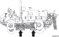
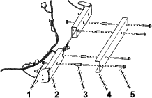
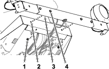
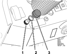
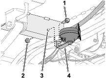
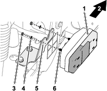
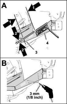
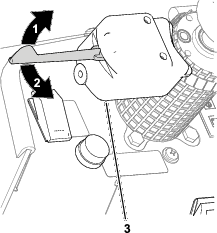
Replacing a Worklight Bulbs

  1. Ensure that the light switch is in the OFF position.

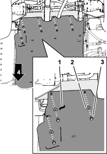
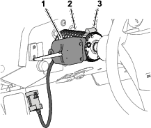
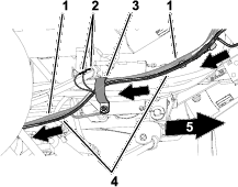
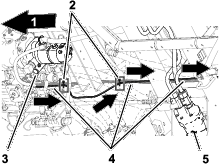
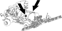
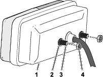
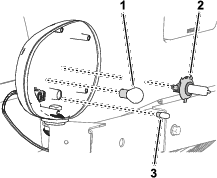
  2. Remove the 6 screws securing the worklight (Figure 73).

    g209233
  3. Remove the worklight cover (Figure 73).

  4. Remove the lamp bulb with the open circuit across the filament wire.

    g208458
  5. Install the new light bulb.

  6. Secure the worklight cover with the 6 screws.

Close section

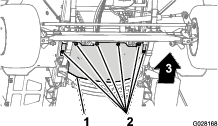
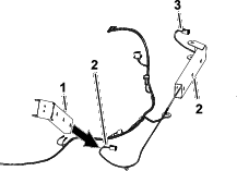
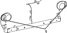
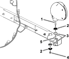
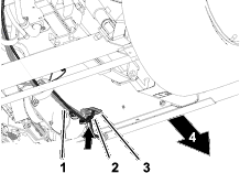
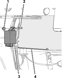
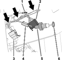
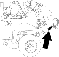
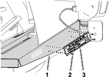
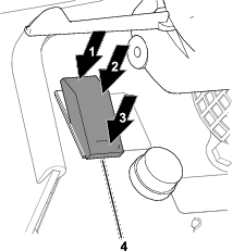
Replacing a Taillight Bulb

  1. Ensure that the light switch is in the OFF position.

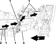
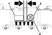
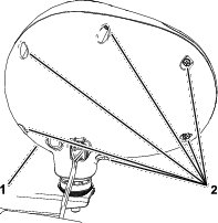
  2. Remove the 2 screws that secure the cover and lens to the taillight base.

  3. Remove the taillight cover.

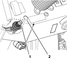
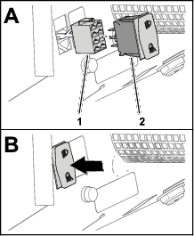
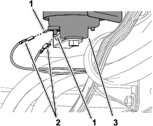
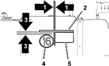
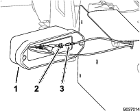
  4. Pushing down on the pin on the light bulb, rotate the light bulb to the left, and pull the light bulb out (Figure 75).

    g024763
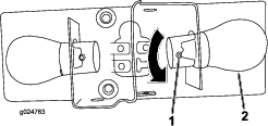
  5. Insert the new light bulb into the socket from which you removed the old light bulb.

  6. Rotate the new light bulb to the right until the pin of bulb aligns with the slot in the light-bulb casing (Figure 75).

  7. Install the taillight cover with the 2 screws.

Close section

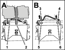
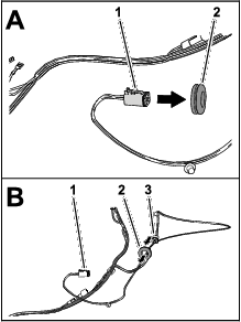
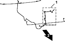
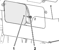
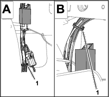
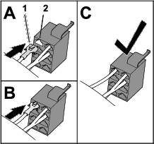
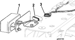
Replacing a License Plate Bulb

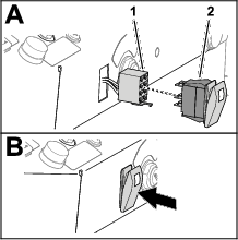
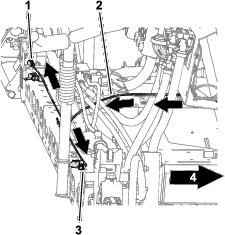
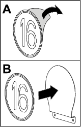
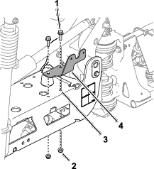
  1. Remove the 2 screws that secure the cover to the base of the license-plate light, and remove the cover (A of Figure 76).

    g037017
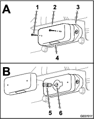
  2. Push down the bulb slightly and rotate it counterclockwise until it is unlocked from the light socket, and remove the bulb (B of Figure 76).

  3. Insert the new light bulb into the bulb socket (B of Figure 76).

  4. Press down the bulb slightly and rotate it clockwise until the bulb locks into the socket (B of Figure 76).

  5. Align the cover to the base of the license-plate light with the lens down (A of Figure 76).

  6. Secure the lens to the base with the 2 screws that you removed in step 1.

Close section
Close section

Replacing Fuses

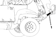
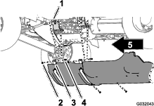
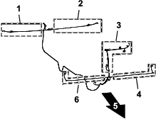
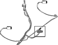
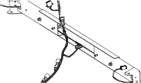
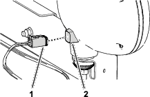
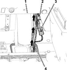
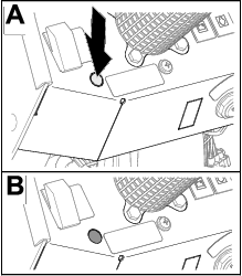
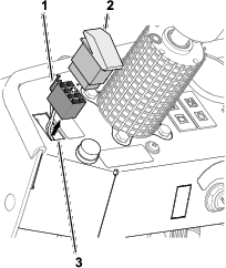
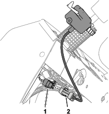
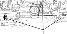
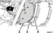
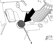
Replacing the Taillight Fuse

g208461

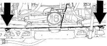
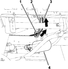
Note: Your machine has separate fuses for the left and right taillights.

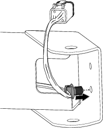
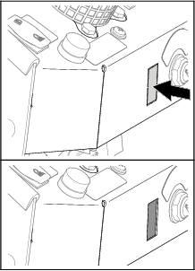
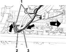
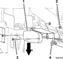
  1. Remove the cover from the fuse socket (Figure 78).

    g037018
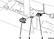
  2. Remove the open fuse (Figure 78).

  3. Insert the new fuse into the socket until the fuse is fully seated (Figure 78).

    Note: Use only a fuse that is rated for the same current load as the fuse that you are replacing.

  4. Assemble the cover onto the fuse socket (Figure 78).

Close section

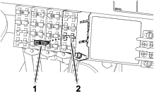
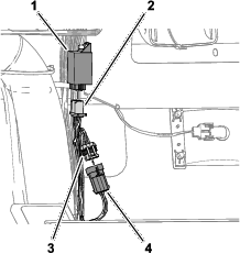
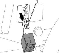
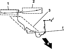
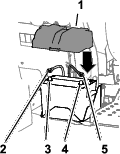
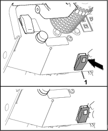
Replacing Fuse Block Fuse

The electrical system is protected by fuses, and requires no maintenance. If a fuse blows, check the component or circuit for a malfunction or short.

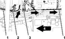
  1. Pull out the open fuse.

  2. Replace the open fuse with a new fuse (Figure 79).

    Note: Ensure that the correct-size fuse is installed.

    g208457
Close section
Close section
Close section