CALIFORNIA
Proposition 65 Warning
Park the machine on a level surface.
Disengage the blade-control switch.
Engage the parking brake.
Move the motion-control levers outward to the NEUTRAL-LOCK position.
Shut off the engine and remove the key.
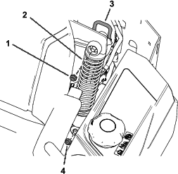
Remove the cam locknut (1/2 inch) securing the top of the existing rear spring (Figure 1).
Retain the cam locknut (1/2 inch).
Remove the flange nut (3/8 inch) securing the bottom of the existing rear spring (Figure 1).
Retain the flange nut (3/8 inch).
Remove the existing rear spring (Figure 1).
Repeat this procedure on the other side.
Parts needed for this procedure:
| Left spring | 1 |
| Right spring | 1 |
Install the new rear spring using the previously removed cam locknut (1/2 inch) and flange nut (3/8 inch) as shown in Figure 1.
With the cam-lock lever in the locked position, torque the cam locknut (1/2 inch) to 15 to 16 N∙m (135 to 145 in-lb).
Repeat this procedure on the other side.
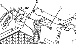
Remove the 2 wheel bolts and 2 flange nuts (3/8 inch) securing the existing front spring (Figure 2).
Retain the 2 wheel bolts and 2 flange nuts (3/8 inch).
Remove the existing front spring (Figure 2).
Parts needed for this procedure:
| Front spring | 1 |
Install the new front spring using the previously removed 2 wheel bolts and 2 flange nuts (3/8 inch) as shown in Figure 2.
Close section