Note: The Ultra Sonic Boom Leveling Kit (Model No. 41219) is required to install this kit.
Note: Determine the left and right sides of the machine from the normal operating position.
CALIFORNIA
Proposition 65 Warning
This product contains a chemical or chemicals known to the State of California to cause cancer, birth defects, or reproductive harm.
Use of this product may cause exposure to chemicals known to the State of California to cause cancer, birth defects, or other reproductive harm.
Park the machine on a level surface.
Engage the parking brake.
Shut off the engine and remove the key.
If you leave the key in the ignition switch, someone could accidently start the engine and seriously injure you or other bystanders.
Remove the key from the ignition switch before you install the kit.
Incorrect battery cable routing could damage the sprayer and cables causing sparks. Sparks can cause the battery gasses to explode, resulting in personal injury.
Always disconnect the negative (black) battery cable before disconnecting the positive (red) cable.
Battery terminals or metal tools could short against metal sprayer components causing sparks. Sparks can cause the battery gasses to explode, resulting in personal injury.
When removing or installing the battery, do not allow the battery terminals to touch any metal parts of the sprayer.
Do not allow metal tools to short between the battery terminals and metal parts of the sprayer.
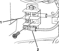
Disconnect the battery by removing the bolt and nut that secures the terminal of the positive-battery cable to the positive post of the battery (Figure 2).
Note: Ensure that the terminal of the battery cable does not touch the post.
Parts needed for this procedure:
| Wire harness | 1 |
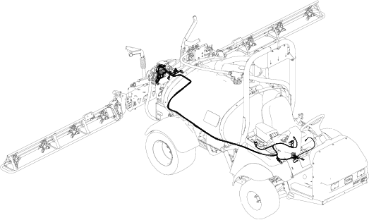
Use the following graphic as an outline of routing the wire harness to the machine (Figure 3).
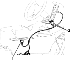
Route the wire harness from the rear of the machine to the console as shown in Figure 4.
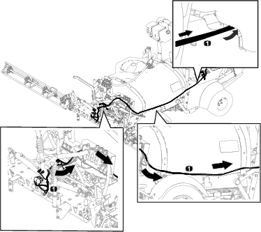
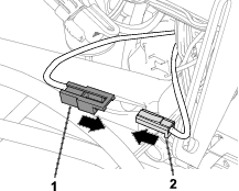
Route the 8-socket connectors through the console (Figure 5).
Install the ultra sonic-mode switch and the boom-lift switches; refer to the Installation Instructions for the ultra sonic boom leveling kit.
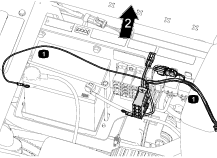
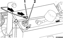
Route the wire harness under the seat (Figure 6).
Install the kit fuse block to the machine fuse block (Figure 7).
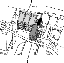
Install the power circuit by attaching the connectors for the machine fuse block and the kit fuse block (Figure 8).
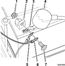
Route the harness to the left from the side console to the flasher module.
Route the harness leg with the ring terminal to the positive post of the battery (Figure 10).
Parts needed for this procedure:
| Lift-manifold bracket | 1 |
| Electronic controller cover | 1 |
Remove the nuts and bolts that secure the mounting bracket to the lift-cylinder manifold and the mount plate (Figure 11).
Retain and set aside the nuts and bolts.
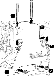
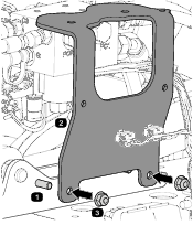
Use the previously removed nuts and bolts to secure the lift-manifold bracket to the mount plate (Figure 12).
Torque the nuts to 1978 to 2542 N∙cm (175 to 225 in-lb).
Secure the new lift-cylinder manifold to the lift-manifold bracket; refer to the Installation Instructions for the ultra sonic boom leveling kit.
Install the electronic controller cover; refer to the Installation Instructions for the ultra sonic boom leveling kit.
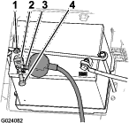
Align the ring terminal for the machine wire harness, the ring terminal of the kit wire harness, and the terminal for the positive battery cable to the positive battery post (Figure 13).
Secure the ring terminals and battery terminal to the battery post (Figure 13) with the bolt and nut removed in Disconnecting the Battery.
Align the insulator cover over the positive battery terminal (Figure 13).