CALIFORNIA
Proposition 65 Warning
Move the machine to a level surface.
Shut off the engine and remove the key.
Set the battery-disconnect switch to the OFF position.
 |  |  |  |  |  |
 |
|||||
| 1x | 2x | 2x (washer) 2x (nut) | 1x | 1x | 1x |
 |  |  |
|||
| 1x | 1x | 10x | |||
Important: Do not route the wire harness near moving parts where it will be pinched or cut.
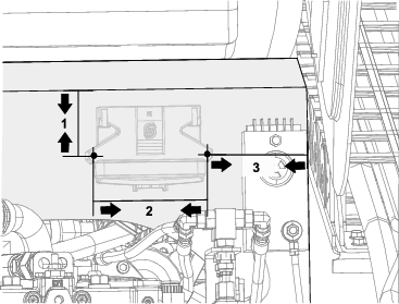
Drill 2 holes into the panel (Figure 2) using the measurements from Figure 3.
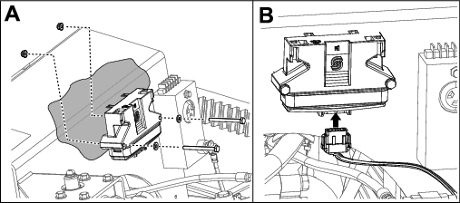
Secure the microprocessor to the panel (Figure 2) using 2 bolts (1/4 x 2 3/4 inches), 2 washers, and 2 nuts (1/4 inch) as shown in Box A of Figure 4.
Plug the wire harness into the microprocessor as shown in Box B of Figure 4.
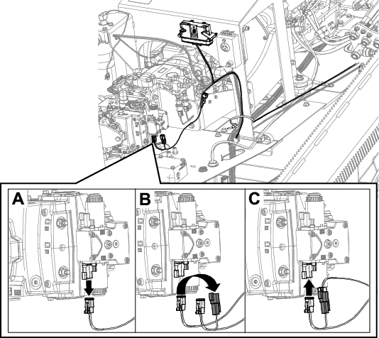
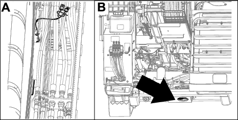
Route the wire harness down to the hydrostat pump.
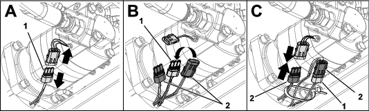
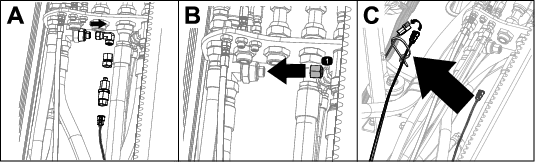
Remove the current wire harness from the hydrostat pump (Box A of Figure 5).
Plug the current wire harness into the new wire harness (Box B of Figure 5).
Install the new wire harness connector in the hydrostat pump (Box C of Figure 5).
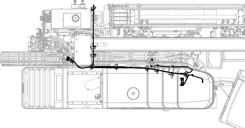
Route the wire harness along the frame with the current wire harnesses (Figure 6 and Figure 7).
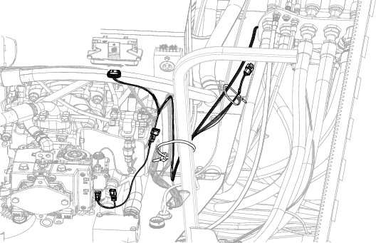
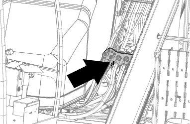
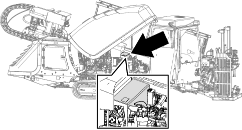
Locate the transducer below the bulkhead, just above the fuel-tank sending unit (Figure 7).
Disconnect the wire harness from the transducer fitting (Box A of Figure 8).
Remove the transducer assembly and fitting currently installed (Box A of Figure 8).
Install the cap onto the port (Box B of Figure 8).
Move the current harnesses over to the frame and connect it to the new wire harness (Box C of Figure 8).
Secure the wire harness using cable ties.
Remove the hose from the fitting on the rear control weldment (Box A of Figure 10).
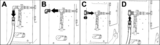
Remove the fitting from the rear control weldment (Box B of Figure 10).
Install the tee fitting on the rear control weldment (Box C of Figure 10).
Install the hose onto the tee fitting (Box D of Figure 10).
Install the fitting removed in 2, shown in Box B of Figure 10 (Box A of Figure 11).
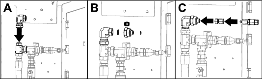
Install the reducer and O-rings (Box B of Figure 11).
Install the transducer assembly removed in 3 of Disconnecting the Transducer (Box C of Figure 11).
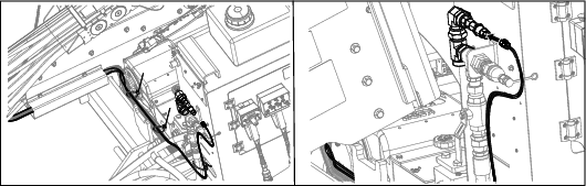
Route the harness along the current harnesses over to the transducer (Figure 12).
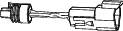
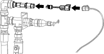
If the harness does not fit into the transducer, connect the harness and transducer using the adapter (Figure 13).
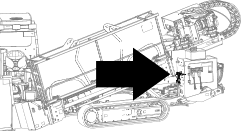
Route the harness to the mud pump sensor (Boxes A and B of Figure 14) at the rear of the machine.
Disconnect the current harness (Box A of Figure 15).
Connect the current harness to the new harness (Box B of Figure 15).
Connect the new harness to the mud pump sensor (Box C of Figure 15).