


Maintenance
Note: Determine the left and right sides of the machine from the normal operating position.
Recommended Maintenance Schedule(s)
| Maintenance Service Interval | Maintenance Procedure |
|---|---|
| After the first 8 operating hours |
|
| After the first 50 operating hours |
|
| After the first 100 operating hours |
|
| Before each use or daily |
|
| Every 50 hours |
|
| Every 100 hours |
|
| Every 150 hours |
|
| Every 200 hours |
|
| Every 300 hours |
|
| Every 500 hours |
|
| Every 600 hours |
|
| Every 800 hours |
|
| Every 1,000 hours |
|
| Before storage |
|
| Yearly |
|
Important: Refer to your engine owner’s manual for additional maintenance procedures.
Caution
If you leave the key in the key switch, someone could accidently start the engine and seriously injure you or other bystanders.
Remove the key from the key switch and disconnect the wires from the spark plugs before you do any maintenance. Set the wires aside so that they do not accidentally contact the spark plugs.
Pre-Maintenance Procedures
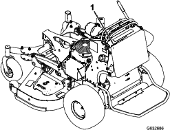
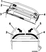
Releasing the Cushion for Rear Access
You can release the cushion for rear access to the machine for maintenance or adjustment.
-
Lower the platform.
-
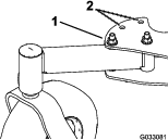
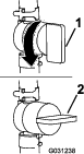
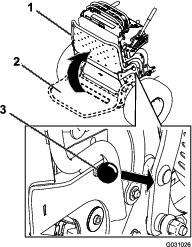
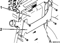
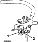
Loosen the twist knobs on each side of the machine (Figure 30).
-
Remove the cushion and lower it to the platform.
-
Perform any maintenance or adjustment on the machine.
-
Raise the cushion, and slide it onto the pins on both sides of the machine.
-
Tighten the twist knobs.
Lubrication
Grease with No. 2 lithium or molybdenum grease.
-
Disengage the PTO and engage the parking brake.
-
Shut off the engine, remove the key, and wait for all moving parts to stop before leaving the operating position.
-
Clean the grease fittings with a rag.
Note: Make sure to scrape any paint off the front of the fitting(s).
-
Connect a grease gun to the fitting.
-
Pump grease into the fittings until grease begins to ooze out of the bearings.
-
Wipe up any excess grease.
Greasing the Accessory Frame
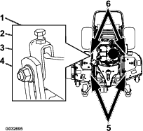
Greasing the Torsion Idler
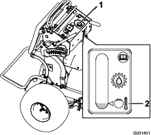
Grease the torsion idler on the mower deck using high-temperature grease at the grease fitting shown in Figure 32.
Important: Use only high-temperature grease.
Greasing the Front Caster Pivots
-
Remove the dust cap and adjust the caster pivots; refer to Adjusting the Caster-Pivot Bearing.
Note: Keep the dust cap off until you have finished greasing the caster pivots.
-
Remove the hex plug.
-
Thread a grease fitting into the hole.
-
Pump grease into the fitting until it oozes out around the top bearing.
-
Remove the grease fitting from the hole.
-
Install the hex plug and dust cap.
Greasing the Caster-Wheel Hubs
Grease type: Lithium or molybdenum grease
-
Park the machine on a level surface, disengage the PTO, and engage the parking brake.
-
Shut off the engine, remove the key, and wait for all moving parts to stop before leaving the operating position.
-
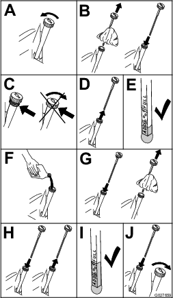
Remove the caster wheel from the caster forks.
-
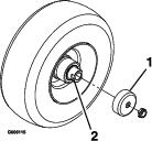
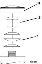
Remove the seal guards from the wheel hub (Figure 33).
-
Remove 1 spacer nut from the axle assembly in the caster wheel.
Note: Thread-locking adhesive has been applied to lock the spacer nuts to the axle. Remove the axle (with the other spacer nut still assembled to it) from the wheel assembly.
-
Pry out the seals, inspect bearings for wear or damage, and replace them if necessary.
-
Pack the bearings with a general-purpose grease.
-
Insert 1 bearing and 1 new seal into the wheel.
Note: You must replace the seals.
-
If both spacer nuts in the axle assembly have been removed (or broken loose), apply a thread-locking adhesive to 1 spacer nut, threading it onto the axle with the wrench flats facing outward.
Note: Do not thread the spacer nut all of the way onto the end of the axle. Leave approximately 3 mm (1/8 inch) from the outer surface of the spacer nut to the end of the axle inside the nut.
-
Insert the assembled nut and axle into the wheel on the side of the wheel with the new seal and bearing.
-
With the open end of the wheel facing up, fill the area inside the wheel around the axle full of general-purpose grease.
-
Insert the second bearing and the new seal into the wheel.
-
Apply a thread-locking adhesive to the second spacer nut, threading it onto the axle with the wrench flats facing outward.
-
Torque the nut to 8 to 9 N∙m (71 to 80 in-lb), loosen it, then torque it to 2 to 3 N∙m (20 to 25 in-lb).
Note: Make sure that the axle does not extend beyond either nut.
-
Install the seal guards over the wheel hub and insert the wheel into the caster fork.
-
Install the caster bolt and tighten the nut fully.
Important: To prevent seal and bearing damage, check the bearing adjustment often by spinning the caster wheel. The wheel should not spin freely (more than 1 or 2 revolutions) or have any side play. If the wheel spins freely, adjust the torque on the spacer nut until there is a slight amount of drag, and apply thread-locking adhesive.
Close sectionEngine Maintenance
Servicing the Air Cleaner
Note: Check the filters more frequently if the operating conditions are extremely dusty or sandy.
Removing the Filters
-
Disengage the PTO, move the motion-control levers to the NEUTRAL-LOCK position, and engage the parking brake.
-
Shut off the engine, remove the key, and wait for all moving parts to stop before leaving the operating position.
-
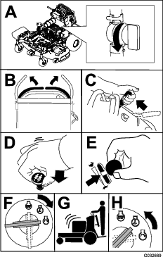
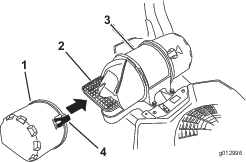
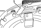
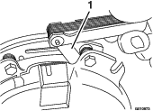
Release the latches on the air cleaner and pull the air-inlet cover off the air-cleaner body (Figure 34).
-
Clean the air-inlet screen and cover.
-
Install the air-inlet cover and secure it with the latches (Figure 34).
-
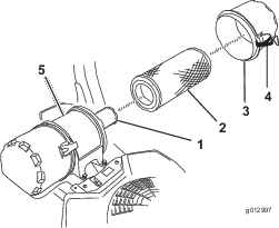
Release the latches on the air cleaner and pull the air-cleaner cover off the air-cleaner body (Figure 35).
-
Clean the inside of the air-cleaner cover with compressed air.
-
Gently slide the primary filter out of the air-cleaner body (Figure 35).
Note: Avoid knocking the filter into the side of the body.
-
Remove the safety filter only if you intend to replace it.
-
Inspect the primary filter for damage by looking into the filter while shining a bright light on the outside of the filter.
Note: Holes in the filter appear as bright spots. If the filter is damaged, discard it.
Servicing the Primary Filter
-
If the primary filter is dirty, bent, or damaged, replace it.
-
Do not clean the primary filter.
Servicing the Safety Filter
Replace the safety filter, never clean it.
Important: Do not attempt to clean the safety filter. If the safety filter is dirty, then the primary filter is damaged. Replace both filters.
Installing the Filters
Important: To prevent engine damage, always operate the engine with both air filters and the cover installed.
-
If installing new filters, check each filter for shipping damage.
Note: Do not use a damaged filter.
-
If you are replacing the safety filter, carefully slide it into the filter body (Figure 35).
-
Carefully slide the primary filter over the safety filter (Figure 35).
Note: Ensure that the primary filter is fully seated by pushing on the outer rim while installing it.
Important: Do not press on the soft, inside area of the filter.
-
Install the air-cleaner cover and secure the latches (Figure 35).
Servicing the Engine Oil
Oil Type: Detergent oil (API service SJ or higher)
Oil Capacity: 1.65L (56 oz) with a filter change; 1.50L (51 oz) without a filter change
Viscosity: See the table below.
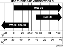
Note: Use a synthetic oil with 5W-20 or 5W-30 rating, up to 4°C (40°F).
Note: Synthetic oils provide better starting when the temperature is below -23°C (-10°F).
Checking the Engine-Oil Level
Note: Check the oil when the engine is cold.
Warning
Contact with hot surfaces may cause personal injury.
Keep your hands, feet, face, clothing and other body parts away the muffler and other hot surfaces.
Important: Do not run the engine with the oil level above the Full mark or below the Low mark. Otherwise, doing so may damage the engine.
-
Disengage the PTO, move the motion-control levers to the NEUTRAL-LOCK position, and engage the parking brake.
-
Shut off the engine, remove the key, and wait for all moving parts to stop before leaving the operating position (Figure 37).
Changing the Engine Oil
Note: Dispose of the used oil at a recycling center.
-
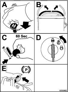
Start the engine and let it run for 5 minutes.
Note: This warms the oil so it drains better.
-
Park the machine so that the rear is slightly lower than the front to ensure that the oil drains completely.
-
Disengage the PTO, move the motion-control levers to the NEUTRAL-LOCK position, and engage the parking brake.
-
Shut off the engine, remove the key, and wait for all moving parts to stop before leaving the operating position (Figure 38).
-
Slowly pour approximately 80% of the specified oil into the filler tube and slowly add the additional oil to bring it to the Full mark (Figure 39).
-
Start the engine and drive to a flat area.
-
Check the oil level again.
Changing the Engine-Oil Filter
Note: Change the engine-oil filter more frequently when operating conditions are extremely dusty or sandy.
-
Drain the oil from the engine; refer to Changing the Engine-Oil Filter.
-
Change the engine-oil filter (Figure 40).
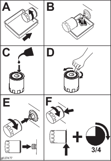
Note: Ensure that the oil-filter gasket touches the engine, then rotate the filter an extra 3/4 turn.
-
Fill the crankcase with the proper type of new oil; refer to Changing the Engine Oil.
Servicing the Spark Plug
Make sure that the air gap between the center and side electrodes is correct before installing the spark plug.
Use a spark plug wrench for removing and installing the spark plug(s) and a gapping tool/feeler gauge to check and adjust the air gap. Install a new spark plug(s) if necessary.
Type for all Engines: Kohler 25 132 14-c, Champion XC12YC, or equivalent
Air Gap: 0.75 mm (0.03 inch)
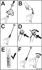
Removing the Spark Plug
-
Disengage the PTO, move the motion-control levers to the NEUTRAL-LOCK position, and engage the parking brake.
-
Shut off the engine, remove the key, and wait for all moving parts to stop before leaving the operating position.
-
Remove the spark plug as shown in Figure 41.
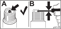
Checking the Spark Plug
Important: Do not clean the spark plug(s). Always replace the spark plug(s) when it has a black coating, worn electrodes, an oily film, or cracks.
If you see light brown or gray on the insulator, the engine is operating properly. A black coating on the insulator usually means the air cleaner is dirty.
Set the gap to 0.75 mm (0.03 inch).
Installing the Spark Plug
Checking the Spark Arrester
Warning
Hot exhaust-system components may ignite fuel vapors even after the engine is shut off. Hot particles exhausted during engine operation may ignite flammable materials. Fire may result in personal injury or property damage.
Do not refuel or run the engine unless the spark arrester is installed.
-
Shut off the engine, wait for all moving parts to stop, engage the parking brake, and remove the key.
-
Wait for the muffler to cool.
-
If any breaks in the screen or welds are observed, replace the arrester.
-
If plugging of the screen is observed, remove the arrester, shake loose particles out of the arrester, and clean the screen with a wire brush (soak in solvent if necessary).
-
Install arrester on exhaust outlet.
Fuel System Maintenance
Draining the Fuel Tank
You can drain the fuel tank by removing it and pouring the fuel out of the fill neck; refer to Removing the Fuel Tank. You can also drain the fuel tank by using a siphon in the following procedure.
Danger
In certain conditions, fuel is extremely flammable and highly explosive. A fire or explosion from fuel can burn you and others and can damage property.
-
Drain fuel from the fuel tank when the engine is cold. Do this outdoors in an open area. Wipe up any fuel that spills.
-
Never smoke when draining fuel, and stay away from an open flame, or where a spark may ignite the fuel fumes.
-
Disengage the PTO, move the motion-control levers to the NEUTRAL-LOCK position, and engage the parking brake.
-
Shut off the engine, remove the key, and wait for all moving parts to stop before leaving the operating position
-
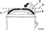
Clean around the fuel cap to prevent debris from getting into the fuel tank (Figure 44).
-
Remove the fuel cap.
-
Insert a syphon pump into the fuel tank.
-
Using the syphon pump, drain the fuel into a clean gas can (Figure 44).
-
Wipe up any spilled fuel.
Removing the Fuel Tank
-
Lower the platform.
-
Release the cushion; refer to Releasing the Cushion for Rear Access.
-
Remove the cross bracket.
-
Remove the fuel tank and set it on the operator platform.
Note: If you want to move the fuel tank further from the machine, remove the fuel and vent lines from the top of the tank.
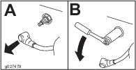
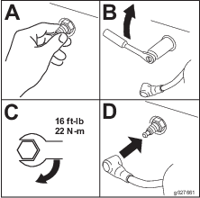
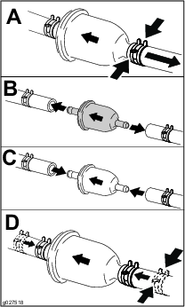
Servicing the Fuel Filter
Replacing the Fuel Filter
Do not install a dirty filter if it is removed from the fuel line.
Note: Wipe up any spilled fuel.
-
Disengage the PTO and engage the parking brake.
-
Shut off the engine, remove the key, and wait for all moving parts to stop before leaving the operating position.
-
Close the fuel-shutoff valve; refer to Using the Fuel-Shutoff Valve.
-
Replace the fuel filter as shown in Figure 46.
Electrical System Maintenance
Servicing the Battery
Always keep the battery clean and fully charged. Use a paper towel to clean the battery case. If the battery terminals are corroded, clean them with a solution of 4 parts water and 1 part baking soda. Apply a light coating of grease to the battery terminals to prevent corrosion.
Voltage: 12V
Warning
CALIFORNIA
Proposition 65 Warning
Battery posts, terminals, and related accessories contain lead and lead compounds, chemicals known to the State of California to cause cancer and reproductive harm. Wash hands after handling.
Danger
Do not drink electrolyte, and avoid contact with skin, eyes or clothing. Wear safety glasses to shield your eyes and rubber gloves to protect your hands.
Battery electrolyte contains sulfuric acid, a deadly poison that causes severe burns.
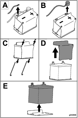
Removing the Battery
Warning
Battery terminals or metal tools could short against metal machine components, causing sparks. Sparks can cause the battery gasses to explode, resulting in personal injury.
-
When removing or installing the battery, do not allow the battery terminals to touch any metal parts of the machine.
-
Do not allow metal tools to short between the battery terminals and metal parts of the machine.
Warning
Incorrect battery-cable routing could damage the machine and cables, causing sparks. Sparks can cause the battery gasses to explode, resulting in personal injury.
-
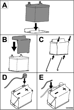
Always disconnect the negative (black) battery cable before disconnecting the positive (red) cable.
-
Always connect the positive (red) battery cable before connecting the negative (black) cable.
-
Disengage the PTO and engage the parking brake.
-
Shut off the engine, remove the key, and wait for all moving parts to stop before leaving the operating position.
-
Remove the battery as shown in Figure 47.
Installing the Battery
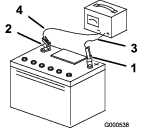
Charging the Battery
Warning
Charging the battery produces gasses that can explode.
Never smoke near the battery and keep sparks and flames away from battery.
Important: Always keep the battery fully charged (1.265specific gravity) to prevent battery damage when the temperature is below 0°C (32°F).
-
Remove the battery from the chassis; refer to Removing the Battery.
-
Check the electrolyte level.
-
Ensure that the filler caps are installed on the battery.
-
Charge the battery for 1 hour at 25 to 30 A or 6 hours at 4 to 6A.
-
When the battery is fully charged, unplug the charger from the electrical outlet, and disconnect the charger leads from the battery posts (Figure 49).
-
Install the battery onto the machine and connect the battery cables; refer to Installing the Battery.
Note: Do not run the machine with the battery disconnected; electrical damage may occur.
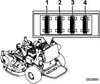
Servicing the Fuses
The electrical system is protected by fuses and requires no maintenance. If a fuse blows, check the component or circuit for a malfunction or short.
-
Release the cushion from the rear of the machine.
-
Pull out the fuse to remove or replace it (Figure 50).
-
Install the cushion to the rear of the machine.
Note: Ensure that the correct-size fuse is installed Figure 50.
Drive System Maintenance
Adjusting the Tracking
Note: Determine the left and right sides of the machine from the normal operating position.
-
Push both control levers forward the same distance.
-
Check if the machine pulls to 1 side.
Note: If it does, shut off the machine and engage the parking brake.
-
Release the cushion from the rear of the machine; refer to Releasing the Cushion for Rear Access.
Note: For easier access, you can also remove the fuel tank; refer to Removing the Fuel Tank.
-
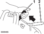
Rotate the left control rod in quarter-turn increments until the machine tracks straight (Figure 51).
Note: If the machine pulls to the right, shorten the control rod by rotating it to the right. If the machine pulls to the left, lengthen the rod by rotating it to the left.
Note: Only adjust the left control rod to match the left wheel speed to the right wheel speed. Do not adjust the right wheel speed, as this positions the right motion-control lever out of the center for the control panel neutral-lock slot.
Important: Do not rotate the control rod too far, as this may cause the machine to creep in neutral.
-
Check for proper tracking, and adjust the rod as necessary.
Note: If you are unable to achieve proper tracking by adjusting the left control rod, contact your Authorized Service Dealer.
-
Check that the machine does not creep from the neutral position with the park brakes disengaged.
-
Install the fuel tank, if you removed it.
-
Install the cushion.
Checking the Tire Pressure
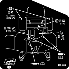
Maintain the air pressure in the rear tires at 83 to 97 kPa (12 to 14 psi).
Important: Uneven tire pressure can cause an uneven cut.
Note: The front tires are semi-pneumatic tires and do not require air-pressure maintenance.
Adjusting the Caster-Pivot Bearing
-
Disengage the blade-control switch (PTO), move the motion control levers to the NEUTRAL-LOCK position, and engage the parking brake.
-
Shut off the engine, remove the key, and wait for all moving parts to stop before leaving the operating position.
-
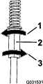
Remove the dust cap from the caster and tighten the locknut (Figure 53).
-
Tighten the locknut until the spring washers are flat, and then back off a 1/4turn to properly set the preload on the bearings (Figure 53).
Important: Make sure that the spring washers are installed correctly as shown in Figure 53.
-
Install the dust cap (Figure 53).
Servicing the Caster Wheels and Bearings
The caster wheels rotate on a roller bearing supported by a spanner bushing. If the bearing is kept well lubricated, wear will be minimal. Failure to keep the bearing well lubricated causes rapid wear. A wobbly caster wheel usually indicates a worn bearing.
-
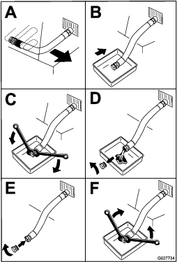
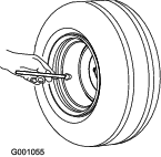
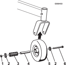
Remove the locknut and wheel bolt holding the caster wheel to the caster fork (Figure 54).
-
Remove 1 bushing, then pull the spanner bushing and roller bearing out of the wheel hub (Figure 54).
-
Remove the other bushing from the wheel hub and clean any grease and dirt from the wheel hub (Figure 54).
-
Inspect the roller bearing, bushings, spanner bushing and the inside of the wheel hub for wear.
Note: Replace any damaged or worn parts (Figure 54).
-
Place 1 bushing into the wheel hub (Figure 54).
-
Grease the roller bearing and spanner bushing, and slide them into the wheel hub (Figure 54).
-
Place the second bushing into the wheel hub (Figure 54).
-
Install the caster wheel into the caster fork and secure it with the wheel bolt and locknut (Figure 54).
-
Tighten the locknut until the spanner bushing bottoms against the inside of the caster forks (Figure 54).
-
Grease the fitting on the caster wheel.
Using the Clutch Shim
Some later model year units have been built with clutches that contain a brake shim. When the clutch brake has worn to the point where the clutch no longer engages consistently, you can remove the shim to extend the clutch life.
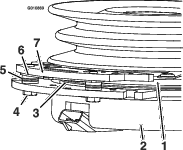
Removing the Clutch Shim
-
Shut off the engine, wait for all moving parts to stop, and remove the key.
-
Engage the parking brake and wait for machine to cool completely.
-
Using an air compressor, blow out any debris under the brake pole and around the brake spacers.
-
Check the condition of the wire-harness leads, connectors, and terminals. Clean or repair them as necessary.
-
Verify that 12 V is present at the clutch connector when the you engage the blade-control switch (PTO).
-
Measure the gap between the rotor and armature. If the gap is greater than 1 mm (0.04 inch), proceed with the following steps:
-
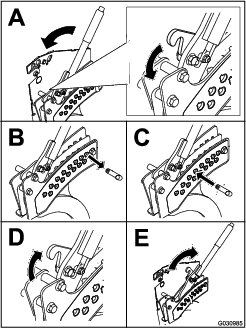
Loosen both brake mounting bolts 1/2 to 1 full turn as shown in Figure 57.
Note: Do not remove the brake pole from the field shell/armature. The brake pole has worn to match the armature and needs to continue to match after you remove the shim to ensure the proper brake torque.
-
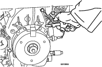
Using needle-nose pliers, or by hand, remove the shim.
Note: Do not discard the shim until you confirm that the clutch functions properly.
-
Using a pneumatic line, blow out any debris under the brake pole and around the brake spacers.
-
Torque each bolt (M6 x 1) to 12.3 to 13.7 N∙m (9.5 to 10.5 ft-lb).
-
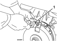
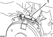
Using a 0.010 inch thick-feeler gauge, verify that a gap is present between the rotor and armature face on both sides of the brake pole as shown in Figure 59 and Figure 60.
Note: Due to the way the rotor and armature faces wear (peaks and valleys), it is sometimes difficult to measure the true gap.
-
If the gap is less than 0.010 inch, then install the shim and refer to .
-
If the gap is sufficient, proceed to the safety check in step 6.
-
-
Perform the following safety check:
-
Sit on the seat and start the engine.
-
Make sure that the blades do not engage when the blade-control switch (PTO) is in the OFF position and the clutch is disengaged.
Note: If the clutch does not disengage, install the shim, and refer to .
-
Engage and disengage the blade-control switch (PTO) 10 consecutive times to ensure that the clutch is functioning properly.
Note: If the clutch does not engage properly, refer to .
-
-
Checking the Wheel-Lug Nuts
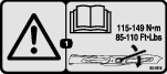
Check and torque the wheel lug nuts to 115 to 142 N∙m (85 to 105 ft-lb).
Close sectionChecking the Wheel-Hub Nuts
Check and torque the wheel hub nuts to 286 to 352 N∙m (211 to 260 ft-lb).
Close sectionCooling System Maintenance
Cleaning the Air-Intake Screen
Before each use, remove any buildup of grass, dirt, or other debris from the cylinder and cylinder-head cooling fins, air-intake screen on the flywheel end, and the carburetor-governor levers and linkage. This helps ensure that adequate cooling and correct engine speed, and reduces the possibility of overheating or mechanical damage to the engine.
Close sectionCleaning the Cooling System
-
Disengage the PTO and engage the parking brake.
-
Shut off the engine, remove the key, and wait for all moving parts to stop before leaving the operating position.
-
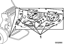
Remove the air-intake screen and fan housing (Figure 61).
-
Clean the debris and grass from the engine parts.
-
Install the air-intake screen and the fan housing (Figure 61).
Brake Maintenance
Servicing the Brake
Before each use, check the brakes on a level surface and slope.
Always engage the parking brake when you stop the machine or leave it unattended.
Important: If the parking brake does not hold securely, adjust it.
Checking the Parking Brake
-
Park the machine on a level surface and disengage the PTO.
-
Shut off the engine, remove the key, and wait for all moving parts to stop before leaving the operating position.
-
Release the brake.
-
Engage the brake lever and ensure that the machine does not move.
-
Adjust the brake if needed.
Adjusting the Brakes
-
Remove the fuel tank; refer to Removing the Fuel Tank.
-
Loosen the bolt on the cable clamp on the left side of the machine.
-
Pull down on the cables until they are taut.
-
Tighten the nut.
-
Install the fuel tank, cross bracket, and cushion.
Belt Maintenance
Replacing the Mower-Deck Belt
Signs of a worn belt include squeaking when the belt is rotating, a slipping blade when cutting grass, a frayed belt edge, burn marks, and cracks. Replace the deck belt if any of these conditions are evident.
-
Disengage the PTO and engage the parking brake.
-
Shut off the engine, remove the key, and wait for all moving parts to stop before leaving the operating position.
-
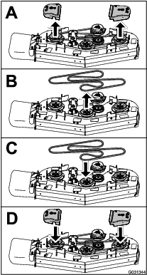
Replace the belt as shown in Figure 63.
Replacing the Transmission Belt
-
Remove the fuel tank; refer to Removing the Fuel Tank.
-
Remove the hydraulic-reservoir cap.
-
Locate the drain plugs in the bottom of the transmission and place a drain pan under the plug (Figure 64).
-
Allow the hydraulic fluid to drain from the machine.
-
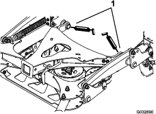
Remove the lower hydraulic hose (Figure 65).
-
Remove the tension spring (Figure 65).
Caution
The spring is under tension when installed and can cause personal injury.
Wear safety glasses and be careful when removing the spring.
-
Remove the deck belt from the clutch and clutch stop (Figure 65).
-
Install the new belt.
-
Install the tension spring and lower hydraulic hose.
-
Install the drain plugs.
-
Add hydraulic fluid to the fill level.
-
Install the hydraulic-reservoir cap.
-
Run the machine for 10 minutes and verify that the hydraulic fluid is at the correct level.
Controls System Maintenance
Adjusting the Motion-Control Levers
If the motion-control levers do not align horizontally, adjust the right side motion-control lever.
-
Disengage the PTO, move the motion-control levers to the neutral position, and engage the parking brake.
-
Shut off the engine, remove the key, and wait for all moving parts to stop before leaving the operating position.
-
Push the motion-control levers down out of the NEUTRAL-LOCK position (Figure 66).
-
Check if the right motion-control lever aligns horizontally with the left motion-control lever (Figure 66).
-
To adjust the motion-control levers horizontally, you must adjust the cam.
-
Release the cushion from the rear of the machine.
-
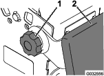
Loosen the nut holding the cam (Figure 67).
-
Adjust the cam until it aligns with the left motion-control lever and tighten the nut for the cam.
Note: Moving the cam clockwise (in the vertical position) lowers the handle; moving the cam counterclockwise (in the vertical position) raises the handle.
Important: Ensure that the flat portion of the cam does not go above a vertical position (right or left); otherwise you may damage the switch.
-
Repeat steps 3 through 8 for the left motion-control lever.
Hydraulic System Maintenance
Servicing the Hydraulic System
Hydraulic Fluid Type: Toro® HYPR-OIL ™ 500 hydraulic fluid
Hydraulic System Fluid Capacity: 4.7 L (5 US qt)
Important: Use the fluid specified. Other fluids could damage the system.
Checking the Hydraulic Fluid
Note: Check the hydraulic fluid level when the fluid is cold.
-
Position the machine on a level surface.
-
Disengage the power takeoff (PTO) and shut off the engine.
-
Wait for all moving parts to stop and engage the parking brake before leaving the operating position.
-
Clean the area around the cap and the filler neck of the hydraulic tank (Figure 68).
-
Remove the cap from the filler neck (Figure 68).
Note: Look inside to check the fluid level in the reservoir.
-
Add fluid to the reservoir until it reaches the fill level.
-
Install the cap on the filler neck.
Warning
Hydraulic fluid escaping under pressure can penetrate skin and cause injury.
-
If hydraulic fluid is injected into the skin, it must be surgically removed within a few hours by a doctor familiar with this type of injury. Gangrene may result if this is not done.
-
Keep your body and hands away from pinhole leaks or nozzles that eject high-pressure hydraulic fluid.
-
Use cardboard or paper to find hydraulic leaks.
-
Safely relieve all pressure in the hydraulic system before performing any work on the hydraulic system.
-
Make sure that all hydraulic-fluid hoses are in good condition, and all that the hydraulic connections and fittings are tight before applying pressure to the hydraulic system.
-
Replacing the Hydraulic Fluid and Filters
Change the hydraulic fluid more frequently in severe conditions or in a hot operating climate. Contact your Authorized Service Dealer for a hydraulic kit to replace the hydraulic filters.
Warning
Hot hydraulic fluid can cause severe burns.
Allow the hydraulic fluid to cool before performing any maintenance on the hydraulic system.
-
Disengage the PTO and engage the parking brake.
-
Shut off the engine and wait for all moving parts to stop before leaving the operating position.
-
Remove the fuel tank; refer to Removing the Fuel Tank.
-
Remove the hydraulic-reservoir cap.
-
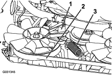
Locate the drain plug in the bottom of each transmission and place a drain pan under the plugs (Figure 69).
-
Remove the drain plugs.
-
Allow the hydraulic fluid to fully drain from the machine.
-
Remove the hydraulic filter cap and filter from each transmission.
-
Install new hydraulic filters with the spring side facing out and install the filter caps.
-
Install the drain plugs.
-
Loosen the vent plug in each transmission so that it is loose and wobbles (Figure 70).
Note: This allows air to escape the hydraulic system as you add hydraulic fluid.

-
Slowly add fluid to the hydraulic tank until it starts to come out 1 of the vent plugs.
Important: Use the fluid specified in Servicing the Hydraulic System or equivalent. Other fluids could cause system damage.
Important: Monitor the level of fluid in the hydraulic tank so that you do not overfill it.
-
Tighten the vent plugs.
-
Install the hydraulic-tank cap.
-
Install the fuel tank.
-
Start the engine and let it run for about 2 minutes to purge air from the system.
-
Shut off the engine and check for leaks.
Note: If 1 or both wheels do not drive, refer to Bleeding the Hydraulic System.
Bleeding the Hydraulic System
The traction system is self-bleeding, however, it may be necessary to bleed the system if fluid is changed or after work is performed on the system.
-
Disengage the PTO and engage the parking brake.
-
Shut off the engine and wait for all moving parts to stop before leaving the operating position.
-
Raise the rear of the machine onto jack stands high enough to raise the drive wheels off the ground.
-
Start the engine and move the throttle control to the idle position.
Note: If the drive wheel does not rotate, it is possible to assist the purging of the system by carefully rotating the tire in the forward direction.
-
Check the hydraulic fluid level as it drops, and add fluid as required to maintain the proper level.
-
Repeat this procedure for the opposite wheel.
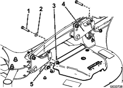
Removing the Mower Deck
-
Shut off the engine, wait for all moving parts to stop, engage the parking brake, and remove the key.
-
Use the height-of-cut lever to lower the mower deck onto wood blocks.
-
Remove the mower-deck belt; refer to Replacing the Mower-Deck Belt.
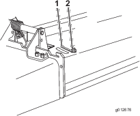
-
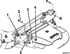
Remove the 2 bolts and 2 nuts connecting the strut bracket to the frame (Figure 71).
Note: Retain the fasteners with the strut bracket.

-
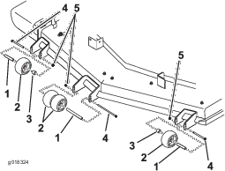
Remove the 2 bolts, 2 nuts, and washer connecting the mower-deck hangers to the lift plates for both sides of the mower deck (Figure 72 and Figure 73).
Note: Retain the mounting hardware with the deck chains.
-
Rotate the caster wheels forward.
-
Slide the mower deck out from under the machine.
Installing the Mower Deck
-
Slide the mower deck under the machine.
-
Rotate the caster wheels rearward.
-
Connect the deck hangers to the lift plates using the 2 bolts, 2 nuts, and 2 washers that you retained for each side of the mower deck.
Note: Mount the front hanger brackets on the outside of the front lift arms for 52-inch decks (Figure 72). Mount the front hanger brackets on the inside of the front lift arms for 60-inch decks (Figure 73).
Note: Torque the bolts to 38 to 49 N∙m (28 to 36 ft-lb).
-
Install the 2 bolts that you retained to connect the strut bracket to the frame (Figure 71).
Note: Torque the bolts to 61 to 75 N∙m (45 to 55 ft-lb).
-
Install the mower-deck belt; refer to Replacing the Mower-Deck Belt.
-
Level the mower deck; refer to Leveling the Mower Deck from Side to Side and Leveling the Mower Deck from Front to Rear.
Servicing the Blades
To ensure a superior quality of cut, keep the blades sharp. For convenient sharpening and replacement, you may want to keep extra blades on hand.
Warning
A worn or damaged blade can break, and a piece of the blade could be thrown at you or bystanders, resulting in serious personal injury or death.
-
Inspect the blades periodically for wear or damage.
-
Replace a worn or damaged blade.
Before Inspecting or Servicing the Blades
Park the machine on a level surface, disengage the blades and engage the parking brake. Shut off the engine, remove the key, and disconnect the spark-plug wires from the spark plugs.
Close sectionInspecting the Blades
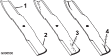
-
Inspect the cutting edges (Figure 74).
-
If the edges are not sharp or have nicks, remove and sharpen the blade; refer to Sharpening the Blades.
-
Inspect the blades, especially in the curved area.
-
If you notice any cracks, wear, or a slot forming in this area, immediately install a new blade (Figure 74).
Checking for Bent Blades
-
Disengage the PTO, move the motion-control levers to the NEUTRAL-LOCK position, and engage the parking brake.
-
Shut off the engine, remove the key, and wait for all moving parts to stop before leaving the operating position.
-
Rotate the blades until the ends face forward and backward.
-
Measure from a level surface to the cutting edge, position A, of the blades (Figure 75).
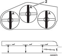
-
Rotate the opposite ends of the blades forward.
-
Measure from a level surface to the cutting edge of the blades at the same position as in step4 above.
Note: The difference between the dimensions obtained in steps 4 and5 must not exceed 3mm (1/8inch).
Note: If this dimension exceeds 3mm (1/8inch), replace the blade.
Warning
A blade that is bent or damaged could break apart and could critically injure you or bystanders.
-
Always replace a bent or damaged blade with a new blade.
-
Do not file or create sharp notches in the edges or surfaces of the blade.
-
Removing the Blades
Replace the blades if they hit a solid object, if a blade is out of balance, or if a blade is bent. To ensure optimum performance and continued safety conformance of the machine, use genuine Toro replacement blades. Replacement blades made by other manufacturers may result in nonconformance with safety standards.
-
Hold the blade end using a rag or a thickly-padded glove.
-
Remove the blade bolt, the curved washer, and the blade from the spindle shaft (Figure 76).
Sharpening the Blades
-
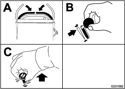
Use a file to sharpen the cutting edge at both ends of the blade (Figure 77).
Note: Maintain the original angle.
Note: The blade retains balance if the same amount of material is removed from both cutting edges.
-
Check the balance of the blade by putting it on a blade balancer (Figure 78).
Note: If the blade stays in a horizontal position, the blade is balanced.

-
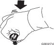
If the blade is not balanced, file some metal off the end of the sail area only (Figure 76).
-
Repeat this procedure until the blade is balanced.
Installing the Blades
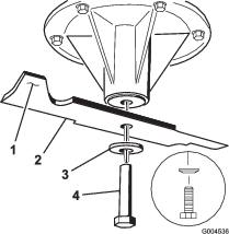
-
Install the blade onto the spindle shaft (Figure 79).
Important: The curved part of the blade must be pointing upward toward the inside of the deck to ensure proper cutting.
-
Install the spring disk and blade bolt (Figure 79).
Note: The spring-disk cone must be installed toward the bolt head (Figure 79).
-
Torque the blade bolt to 115 to 150N∙m (85 to 110ft-lb).
Correcting the Quality of Cut
If a deck blade cuts lower than the other, correct it as follows:
Note: Tire air pressure is critical in these procedures; make sure that the rear tires have the correct pressure.
-
Disengage the PTO and engage the parking brake.
-
Shut off the engine, remove the key, and wait for all moving parts to stop before leaving the operating position.
-
Disconnect the spark-plug wire(s) from the spark plug(s).
-
Adjust the tire pressure in the rear tires to 83 to 97 kPa (12 to 14 psi).
-
Check that the blades and spindle shafts are not bent; refer to Checking for Bent Blades.
-
Set the height-of-cut to the 7.6 cm (3 inches) position; refer to Adjusting the Height-of-Cut.
Checking the Mower Deck Side-to-Side Height
-
Adjust the rear-tire pressure.
-
Ensure that the blades are not bent; refer to Checking for Bent Blades.
-
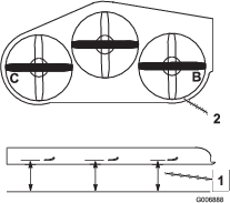
Position the blades side-to-side.
-
Measure at the B and C locations from a level surface to the cutting edge of blade tips (Figure 80).
-
The difference between measurements B and C should be no more than 6 mm (1/4 inch).
Note: If it is not correct, refer to Leveling the Mower Deck from Side to Side.
Leveling the Mower Deck from Side to Side
-
Loosen the side nut and jam nut in the yokes you want to adjust (Figure 81).
-
Rotate the top bolt of the yokes to adjust the height of the mower deck (Figure 81).
Note: Rotate the bolts clockwise to raise the deck; rotate the bolt counterclockwise to lower it.
-
Tighten the jam nuts and side bolts.
-
Check the side-to-side height; refer to Checking the Mower Deck Side-to-Side Height.
Checking the Mower Deck Front-to-Rear Pitch
-
Adjust the tire pressure in the rear tires to the correct specifications.
-
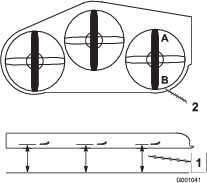
Position 1 blade front-to-rear. Measure at A and B locations from a level surface to the cutting edge of the blade tips (Figure 82).
Note: The mower blade should be 6 mm (1/4 inch) lower in front at A than in the rear at B.
-
Rotate the blades and repeat for other blades.
-
If the front-to-rear pitch is not correct, refer to Leveling the Mower Deck from Front to Rear.
Leveling the Mower Deck from Front to Rear
-
Loosen the jam nut and side bolt in the yokes that you want to adjust (Figure 83).
-
Rotate the top bolt of the yokes to adjust the height of the mower deck (Figure 83).
Note: Rotate the bolt clockwise to raise the deck; rotate the bolt counterclockwise to lower it.
-
Tighten the jam nuts and side bolts.
-
Check the front-to-rear pitch; refer to Checking the Mower Deck Front-to-Rear Pitch.
Matching the Height-of-Cut
-
Check the rear tire pressure.
-
Set the height-of-cut to the 7.6 cm (3 inches) position; refer to Adjusting the Height-of-Cut.
-
With the machine on level surface, position 1 blade front-to-rear.
-
Measure at A, and from a level surface to the cutting edge of the blade tips (Figure 84).
Note: The measurement should be 7.6 cm (3 inches).
-
If the measurement is not correct, locate the front 2 yokes on the machine (Figure 83).
-
Loosen the side bolt and jam nut of the yokes.
-
Adjust the top bolt of the yokes until the blade tips match 7.6 cm (3 inches).
-
Tighten the jam nuts and side bolts.
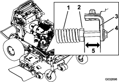
Adjusting the Deck-Lift Spring
Note: Adjusting the deck-lift spring alters how much the deck floats and how much effort it takes to lift the deck when using the height-of-cut handle.
-
Raise the deck-lift lever and lock it into the TRANSPORT position.
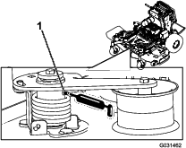
-
Check the length between the spring nut and the rear side of the welded mount bracket (Figure 85).
-
Ensure that the length is between 47 to 50 mm (1.8 to 2 inches) (Figure 85).
-
If needed, adjust the distance by adjusting the bolt on the front of the mount bracket (Figure 85).
-
Repeat this procedure for the opposite deck-lift spring.
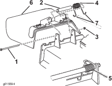
Replacing the Grass Deflector
Warning
An uncovered discharge opening could allow the machine to throw objects toward you or bystanders, resulting in serious injury. Also, contact with the blade could occur.
Do not operate the machine unless you install a cover plate, a mulch plate, grass deflector, or bagger.
-
Remove the locknut, bolt, spring, and spacer holding the deflector to the pivot brackets (Figure 86).
-
Remove the damaged or worn grass deflector.
-
Place the spacer and the spring onto the grass deflector.
-
Place 1 J-hook end of the spring behind the deck edge.
Note: Make sure that 1 J-hook end of spring is installed behind deck edge before installing the bolt as shown in Figure 86.
-
Install the bolt and the nut.
-
Place 1 J-hook end of the spring around the grass deflector (Figure 86).
Important: The grass deflector must be able to rotate. Lift the deflector up to the full open position, and ensure that it rotates into the full-down position.
Cleaning under the Machine
Remove the grass buildup under the machine daily.
-
Disengage the PTO, move the motion-control levers to the NEUTRAL-LOCK position and engage the parking brake.
-
Shut off the engine, remove the key, and wait for all moving parts to stop before leaving the operating position.
-
Raise the front of the machine and use jack stands to support the machine.
Disposing of the Waste
Engine oil, batteries, hydraulic-fluid, and engine coolant are pollutants to the environment. Dispose of these according to your state and local regulations.
Close section