Setup
Installing the Rails and Ramps
Parts needed for this procedure:
| Left tube assembly | 1 |
| Right tube assembly | 1 |
| Carriage bolt | 8 |
| Flat washer | 8 |
| Locknut | 8 |
| Load ramp | 2 |
| Spacer | 2 |
| Hex-head screw | 2 |
| Rubber tube | 2 |
| Nut | 2 |
| Locking bracket | 2 |
| Bracket screw | 4 |
| Bracket nut | 4 |
| Narrow wheel rod | 4 |
| Capscrew (for models prior to serial #220000001) | 6 |
-
Raise and secure the trailer.
-
Remove the 4 lug nuts securing the tires and remove the tires to access the wheel rods.
-
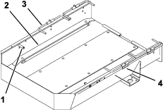
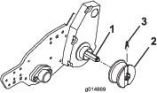
If equipped, remove the fasteners securing the standard inserts to the bottom of the ramp and remove the inserts (Figure 1).
-
Remove the existing trailer stops, wheel rods, and brackets from the trailer (Figure 1).
Note: Save the trailer stops, brackets, and hardware for later installation.
-
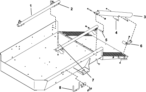
Secure the tube assembly mounting brackets to the square holes in each side of the trailer with 4 carriage bolts, flat washers and locknuts (Figure 2). Position the tube assemblies so that the cross tubes are to the rear.
Note: On trailers with serial numbers prior to 220000001: all tube assembly mounting holes are not in the sides of the trailer and will have to mounted as follows:
-
Secure the upper rear hole in the tube assembly mounting bracket to the top rear square hole in the side of the trailer.
-
Position the tube assembly so it is parallel to the top of the trailer.
-
Using the tube assembly mounting brackets as templates, locate, mark, and drill 3 holes with .390 inch (9.9 mm) diameters in each side of the trailer.
-
Secure the tube assembly mounting brackets to each side of the trailer with 3 capscrews (3/8 x 3/4 inch) in place of the carriage bolts, flat washers, and locknuts.
-
-
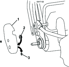
Mount a load ramp to the rear of each tube assembly with a 3/6 x 2-1/2 inch capscrew, spacer, and locknut (Figure 2).
-
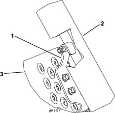
Install a hex-head screw through each of the center holes in the load ramps and through the 2 rubber tubes (Figure 4).
-
Position a locking bracket onto each side of the ramp so they align with the underside of the load ramps, engage with the coated pins in the load ramps and aligns with the holes in the ramp (Figure 2 and Figure 4). Only one set of the mounting holes is used per locking bracket.
-
Loosely mount each locking bracket to the ramp with 5/16 x 3/4 inch flange head screws and flange nuts (Figure 2 and Figure 4).
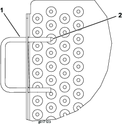
Note: If the ramp handle interferes with the mounting fastener of the locking bracket, grind off the end of the handle to expose the hole, as required (Figure 3). Touch up the paint.
-
Raise and lock the ramp. Adjust the locking brackets so they are engaged on the pins and tighten the flange screws and nuts (Figure 2 and Figure 4).
-
Mount the narrow wheel rods pointed upward to the mounting holes in each side of the trailer, using the brackets and fasteners removed in step 4 (Figure 2).
Note: Ensure the brackets are flush to the top of the trailer frame.
Note: On trailers with serial numbers prior to 220000001: You must purchase 2 new rod brackets, Part No. 105-5395 and 2 new retaining clips, Part No. 99-6204 to replace the existing components on the trailer.
-
Raise and lower the narrow wheel rods to ensure that they are installed correctly; the rods should move smoothly and should not be able to slide out of the brackets.
-
Install the tires that were removed in step 2; torque the lug nuts to 80 ft-lb (108.5 Nm).
Installing the Rail Wheels
Parts needed for this procedure:
| Felt seal | 2 |
| Rail wheel | 4 |
| Wheel clip | 4 |
-
Remove the existing standard transport wheels from the wheel shafts on the greensmower (if equipped).
-
On the Greensmaster Flex 18 or 21 machines only, proceed as follows:
-
Insert a rail wheel onto each shaft and secure it with a wheel clip (Figure 6).
Important: The Flex 1800/1820 and 2100/2120 Series machines require a different wheel off set than all other Toro Greensmowers. Read and follow the mounting instructions molded into the sides of the wheels.
Loading the Machine
Lower the load ramps, roll the machines onto the rails, and secure the wheels in the wheel stops (Figure 7).
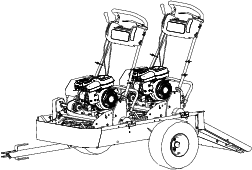
Note: When trailering only 1 machine, mount the wheel rods to the middle set of mounting holes in the trailer.