


Maintenance
Recommended Maintenance Schedule(s)
| Maintenance Service Interval | Maintenance Procedure |
|---|---|
| After the first 2 hours |
|
| After the first 5 hours |
|
| Before each use or daily |
|
| Every 50 hours |
|
| Every 100 hours |
|
| Yearly |
|
| Yearly or before storage |
|
Important: You can find more information about maintaining and servicing your machine at www.Toro.com.
Maintenance Safety
Read the following safety precautions before performing any maintenance on the machine:
-
Before performing any maintenance, service, or adjustment, shut off the engine and remove the key. If major repairs are ever needed, contact an Authorized Service Dealer.
-
Check all fasteners at frequent intervals for proper tightness to ensure that the machine is in safe working condition.
-
Do not change the governor settings on the engine.
-
Purchase only genuine Toro replacement parts and accessories.
Preparing for Maintenance
-
Move the machine to a level surface.
-
Shut off the engine and wait for all moving parts to stop.
-
Disconnect the spark-plug wire. Refer to Replacing the Spark Plug.
Checking the Engine-Oil Level
| Maintenance Service Interval | Maintenance Procedure |
|---|---|
| Before each use or daily |
|

Checking and Adjusting the Skids and Scraper
| Maintenance Service Interval | Maintenance Procedure |
|---|---|
| Yearly |
|
Check the skids to ensure that the auger does not contact the paved or gravel surface. Adjust the skids as needed to compensate for wear.
-
Check the tire pressure; refer to Checking the Tire Pressure.
-
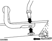
Loosen the nuts that secure both skids to the auger sides until the skids slide up and down easily (Figure 41).
-
Support the side plates so that they are at least 1.3 cm (1/2 inch) above a level surface.
Important: The auger blades must be supported above the ground by the skids.
-
Ensure that the scraper is 3 mm (1/8 inch) above and parallel to a level surface.
Note: If the pavement is cracked, rough, or uneven, adjust the skids to raise the scraper. For gravel surfaces, adjust the skids further down to prevent the machine from picking up rocks.
-
Move the skids down until they are even with the ground.
-
Firmly tighten the nuts that secure both skids to the auger sides.
Note: To quickly adjust the skids if they loosen, support the scraper 3 mm (1/8 inch) off the pavement, then adjust the skids down to the pavement.
Note: If the skids become excessively worn, you can turn them over and set the unused side toward the pavement.
Checking and Adjusting the Traction Cable
| Maintenance Service Interval | Maintenance Procedure |
|---|---|
| After the first 2 hours |
|
| Yearly |
|
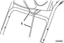
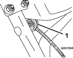
If the machine does not drive in the forward or reverse speeds or it drives when you release the traction lever, adjust the traction cable.
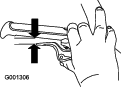
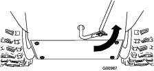
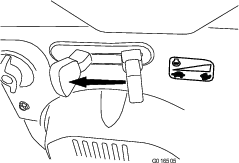
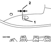
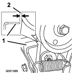
With the traction lever disengaged, check the pin in the elongated slot in the left side of the machine above the tire. There should be a gap of 1 to 1.5 mm (1/32 to 1/16 inch) from the front of the slot to the front edge of the pin (Figure 42).
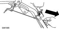
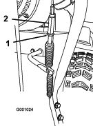
If the left (traction) cable is not properly adjusted, do the following steps:
-
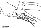
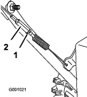
Loosen the jam nut.
-
Loosen or tighten the turnbuckle to adjust the pin until it is the proper gap from the front edge of the slot.
-
Tighten the jam nut (Figure 43).
Checking and Adjusting the Auger/Impeller Cable
| Maintenance Service Interval | Maintenance Procedure |
|---|---|
| After the first 2 hours |
|
| Yearly |
|
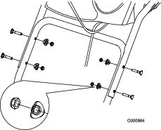
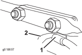
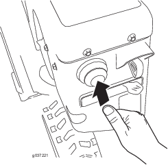
-
Remove the 2 screws from the right side of the belt cover as shown.
-
Lift up the right side of the belt cover (Figure 44).

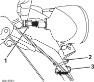
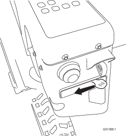
-
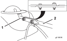
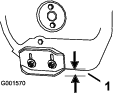
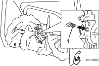
With the auger/impeller lever disengaged, ensure that the gap between the auger clutch assembly and the tab is 1.5 mm (1/16 inch) as shown in Figure 45.
-
If the auger/impeller cable is not properly adjusted, do the following steps:
-
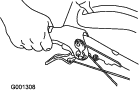
Loosen the jam nut (Figure 46).
-
Loosen or tighten the turnbuckle that adjusts the tension on the cable (Figure 46).
-
Adjust the turnbuckle until you obtain the proper gap.
-
Tighten the jam nut.
-
Insert the 2 screws that you previously removed on the belt cover.
-
If the auger/impeller cable is properly adjusted but a problem remains, contact an Authorized Service Dealer.
Checking the Auger-Gearbox-Oil Level
| Maintenance Service Interval | Maintenance Procedure |
|---|---|
| Yearly |
|
-
Move the machine to a level surface.
-
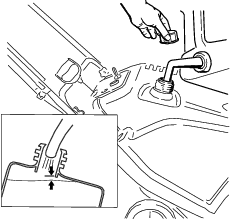
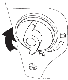
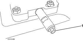
Clean the area around the pipe plug (Figure 47).
-
Remove the pipe plug from the gearbox.
-
Check the oil level in the gearbox. The oil should be at the point of overflowing at the filler opening.
-
If the oil level is low, add GL-5 or GL-6, SAE 85-95 EP gear oil lubricant to the gearbox until the point of overflow.
Note: Do not use synthetic oil.
-
Install the pipe plug in the gearbox.
Changing the Engine Oil
| Maintenance Service Interval | Maintenance Procedure |
|---|---|
| After the first 5 hours |
|
| Every 50 hours |
|
If possible, run the engine for a few minutes before changing the oil because warm oil flows better and carries more contaminants.
| Engine oil capacity | 0.89 to 0.95 L (30 to 32 fl oz) |
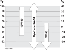
| Oil viscosity | Refer to Figure . |
| API service classification | SJ or higher |
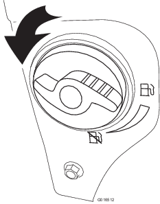
Use Figure 48 below to select the best oil viscosity for the outdoor temperature range expected:
-
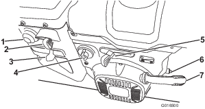
Clean the area around the oil-drain cap (Figure 49).
-
Slide an oil-drain pan under the drain extension and remove the oil-drain plug.
Note: When removing the plug, ensure that the tube does not loosen.
-
Drain the oil.
Note: Dispose of the used oil properly at a local recycling center.
-
Install the oil-drain plug.
-
Fill the crankcase with oil.
Replacing the Spark Plug
| Maintenance Service Interval | Maintenance Procedure |
|---|---|
| Every 100 hours |
|
Warning
Replacing the spark plug while the engine is hot can result in burns.
Wait until the engine is cool to replace the spark plug.
Use a Toro spark plug or equivalent (Champion® RN9YC or NGK BPR6ES).
-
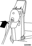
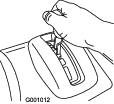
Remove the boot (Figure 50).
-
Clean around the base of the spark plug.
-
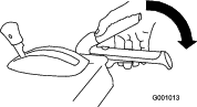
Remove and discard the old spark plug.
Note: You will need a ratchet wrench extension to remove the spark plug.
-
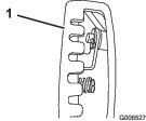
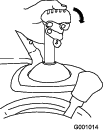
Set the gap between the electrodes on a new spark plug at 0.76 mm (0.030 inch) as shown in Figure 52.

-
Install the new spark plug, tighten it firmly, and attach the ignition wire to the spark plug.
Note: Ensure that the ignition wire snaps completely into place on the spark plug.
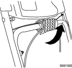
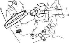
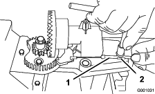
Adjusting the Discharge-Chute Latch
If the discharge chute does not lock into the desired position or does not unlock so that you can move it to another position, adjust the discharge-chute latch.
-
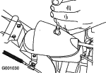
Remove the fastener on the gear cover (Figure 53), lift the front of the cover up, and slide it back and out of the way.
-
Loosen the bolt on the cable clamp (Figure 54).
-
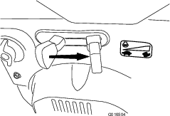
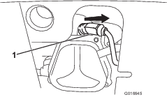
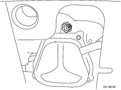
Grasp the cable conduit and move it toward the front of the machine until the discharge-chute latch fully engages the gear teeth (Figure 54 and Figure 55).
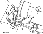
Note: The latch is spring loaded and naturally moves into the teeth of the gear (Figure 55).
-
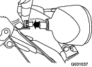
Remove any slack in the cable by pulling the cable conduit rearward.
-
Tighten the bolt on the cable clamp, being careful not to strip the plastic part.
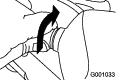
-
Install and secure the gear cover.
Replacing the Drive Belts
If the auger/impeller drive belt or the traction-drive belt becomes worn, oil-soaked, or otherwise damaged, have an Authorized Service Dealer replace the belt.
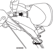
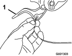
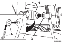
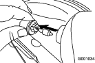
Replacing the Headlight Bulb
Use a GE 899 37W halogen light bulb. Do not touch the bulb with your hands or allow dirt or moisture to come into contact with the bulb.
-
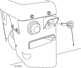
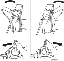
Remove the wire connector from the back of the headlight (Figure 56).
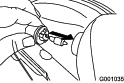
-
Turn the base of the bulb counterclockwise until it stops (Figure 57).
-
Remove the bulb straight out from the back of the headlight (Figure 58).
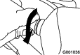
-
Insert a new bulb into the back of the headlight (Figure 59).
-
Turn the base of the bulb clockwise until it is snug (Figure 60).
-
Insert the wire connector straight into the back of the headlight until it is securely in place (Figure 61).