CALIFORNIA
Proposition 65 Warning
Move the machine to a level surface.
Shut off the engine and remove the key.
Set the battery-disconnect switch to the OFF position.
 |  |  |  |
| 5x | 1x | 1x | 1x |
 |
|||
| 1x | |||
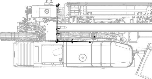
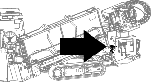
Locate the transducer below the bulkhead, just above the fuel-tank sending unit (Figure 1).
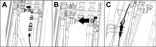
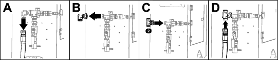
Disconnect the wire harness from the transducer fitting (Box A of Figure 2).
Remove and save the transducer assembly and fitting currently installed (Box A of Figure 2).
Install the cap onto the port (Box B of Figure 2); torque to 79 to 98 N∙m (58 to 72 ft-lb).
Connect the existing harnesses to the new wire harness (Box C of Figure 2).
Important: Do not route the wire harness near moving parts.
Secure the wire harness using a cable tie.
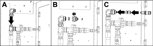
Remove the hose from the fitting on the rear control weldment (Box A of Figure 4).
Remove and save the fitting from the rear control weldment (Box B of Figure 4).
Install the tee fitting on the rear control weldment (Box C of Figure 4); torque the fitting to 301 to 336 N∙m (222 to 248 ft-lb). .
Install the hose onto the tee fitting (Box D of Figure 4).
Install the fitting (Box A of Figure 5) that was removed in step 2 (shown in Box B of Figure 4).
Torque the fitting to 301 to 336 N∙m (222 to 248 ft-lb).
Install the reducer and O-rings (Box B of Figure 5); torque the reducer to 301 to 336 N∙m (222 to 248 ft-lb). .
Install the transducer assembly (Box C of Figure 5) that was removed in step 3 of Disconnecting the Transducer.
Torque the transducer adapter to 79 to 98 N∙m (58 to 72 ft-lb) and the transducer to 46 to 57 N∙m (34 to 42 ft-lb).
Route the harness along the existing harnesses over to the transducer (Figure 6).
Important: Do not route the wire harness near moving parts.
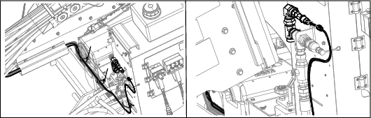
Secure the harness using the cable ties (Figure 7).