Note: Retain these instructions with the Operator’s Manual for the machine.

Warning

CALIFORNIA

Proposition 65 Warning

Read this information carefully to learn how to operate and maintain your product properly and to avoid injury and product damage. You are responsible for operating the product properly and safely.

You may contact Toro directly at www.Toro.com for product safety and operation training materials, accessory information, help finding a dealer, or to register your product.

Whenever you need service, genuine Toro parts, or additional information, contact an Authorized Service Dealer or Toro Customer Service and have the model and serial numbers of your product ready. Figure 1 identifies the location of the model and serial numbers on the product. Write the numbers in the space provided.

g214500

Safety

Safety and Instructional Decals

Graphic

Safety decals and instructions are easily visible to the operator and are located near any area of potential danger. Replace any decal that is damaged or missing.

decal93-7814
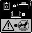
decal115-4212
decal115-4855
Close section
Close section

Setup

Note: Determine the left and right sides of the machine from the normal operating position.

Important: If you are installing this kit onto the Grandstand Multi Force Snow Machine, you also need to install a clutch onto the machine. Contact your Authorized Service Dealer.

Preparing the Machine

  1. Park the machine on a level surface.

  2. Disengage the PTO, engage the parking brake, and move the motion-control levers outward to the NEUTRAL-LOCK position.

  3. Shut off the engine and remove the key.

Close section

Installing the High-Flow Assembly

Parts needed for this procedure:

High-flow assembly1
Rear bracket1
Latch pin1
Small hairpin cotter1
Large hairpin cotter1
Front bracket1
Carriage bolt (3/8 x 2-3/4 inches)2
Spacer2
Nut (3/8 inch)3
Carriage bolt (3/8 x 1-1/4 inches)1
Backplate1

Note: You may need a second person or jackstands to hold up the assembly as you install it to the machine.

  1. Remove the mower deck; refer to the Operator’s Manual for the machine.

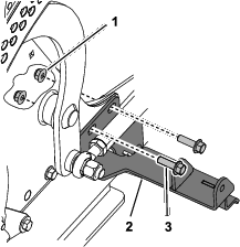
  2. Remove the 2 bolts (3/8 x 1-1/4 inches) and 2 nuts (3/8 inch) from the right side of the machine (Figure 2).

    Important: Ensure that the fan shroud inside the frame does not fall onto the transaxle as you remove the hardware.

    g209230
  3. Use the bolts and nuts you just removed to secure the rear bracket from the kit and the fan shroud to the machine frame (Figure 2). Torque to 41 to 49 N∙m (30 to 36 ft-lb).

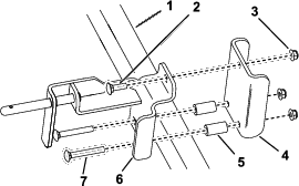
  4. Loosely install the front bracket and back plate to the right tube frame, approximately 44 cm (17-1/4 inches) in front of the rear bracket (Figure 3), using 1 carriage bolt (3/8 x 1-1/4 inches), 2 carriage bolts (3/8 x 2-3/4 inches), 2 spacers, and 3 nuts (3/8 inch) as shown in (Figure 4).

    g210668
    g209229
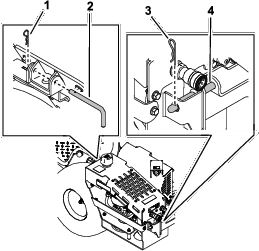
  5. Install the high-flow assembly onto the front and rear brackets, adjusting the front bracket as necessary. Secure the assembly to rear bracket using the small hairpin cotter and latch pin, and secure it on the mount pin of the front bracket using the large hairpin cotter (Figure 5).

    g209503
  6. Torque the bolts on the front and rear brackets to 37 to 45 N∙m (27 to 33 ft-lb).

Close section

Routing the Belt

Parts needed for this procedure:

Belt1

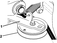
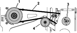
Route the belt around the machine clutch pulley and idler pulley (Figure 6).

Note: The belt comes from the factory already attached to the high-flow pump pulley. Use a ratchet to pull back the idler arm to relieve tension on the spring; you do not need to remove the spring from the idler pulley (Figure 7)

g209259
g214199
Close section
Close section

Operation

Connecting an Attachment

Important: Do not engage the machine PTO without an attachment connected to the high-flow assembly.

Important: Check the hydraulic-fluid level before engaging the attachment; refer to Checking the Hydraulic Fluid.

  1. Park the machine on a level surface, disengage the PTO, engage the parking brake, and move the motion-control levers outward to the NEUTRAL-LOCK position.

  2. Shut off the engine and remove the key.

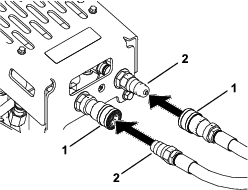
  3. Connect the attachment hoses to the high-flow assembly quick-disconnect couplers (Figure 8).

    Note: Wipe any dirt and contaminants from the couplers before connecting them to the attachment hoses.

    g209505
  4. Start the engine.

  5. Move the engine throttle between 1/2 and 3/4 throttle and engage the PTO.

    Note: In cold weather, allow the attachment to run for a few minutes before increasing the throttle to full throttle.

  6. Ensure that the attachment runs smoothly prior to operation under normal work conditions.

Close section

Removing the Assembly

  1. Park the machine on a level surface, disengage the PTO, engage the parking brake, and move the motion-control levers outward to the NEUTRAL-LOCK position.

  2. Shut off the engine and remove the key.

  3. Disconnect any attachments from the quick-disconnect couplers. Cover the couplers.

  4. Remove the belt (Figure 6).

  5. Remove the small hairpin cotter and latch pin from the rear of the assembly (Figure 9).

    g209503
  6. Remove the large hairpin cotter from the mount pin on the front of the assembly (Figure 9).

  7. Lift the assembly off the front and rear brackets attached to the machine.

    Note: If you are installing the mower deck, you do not need to remove the brackets.

  8. If you will be installing a bagger to the machine, remove the front and rear brackets (see Figure 2 and Figure 4). Install the bolts and nuts from the rear bracket to the secure the fan shroud to the machine.

    Important: Ensure that the fan shroud inside the frame does not fall onto the transaxle as you remove the hardware.

Note: To install the assembly on the machine again, refer to Installing the High-Flow Assembly.

Close section
Close section

Maintenance

Recommended Maintenance Schedule(s)

Maintenance Service IntervalMaintenance Procedure
Before each use or daily
  • Check the hydraulic-fluid level.
  • Clean debris from the cooler.
  • Every 100 hours
  • Check the belt.
  • Every 250 hours
  • Change the hydraulic fluid, filter, and screen fitting.
  • Checking the Hydraulic Fluid

    Hydraulic Fluid Type: Toro® HYPR-OIL ™ 500 hydraulic oil

    Hydraulic Fluid Capacity: 4.7 L (1.25 US gallons)

    1. Park the machine on a level surface, disengage the PTO, engage the parking brake, and move the motion-control levers outward to the NEUTRAL-LOCK position.

    2. Shut off the engine and remove the key. Allow the machine to cool.

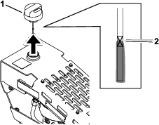
    3. Remove the breather cap and wipe off the dipstick with a clean rag (Figure 10).

    4. Insert the dipstick into the tank, but do not thread the cap; then remove it and check the fluid level (Figure 10).

      Note: The fluid level should be between the upper and lower lines on the dipstick.
      g209517
    5. If the fluid level is low, add hydraulic fluid to the tank until the level is between the upper and lower lines on the dipstick (Figure 10).

    6. Install the breather cap.

    Close section

    Changing the Hydraulic Fluid, Filter, and Screen Fitting

    1. Park the machine on a level surface, disengage the PTO, engage the parking brake, and move the motion-control levers outward to the NEUTRAL-LOCK position.

    2. Shut off the engine and remove the key. Allow the machine to cool.

      Warning

      Hot hydraulic fluid can cause severe burns.

      Allow the hydraulic fluid to cool before performing any maintenance on the hydraulic system.

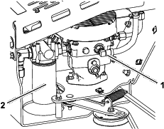
    3. Place a drain pan under the 90-degree fitting (Figure 11).
      g209562
    4. Remove the hose from the fitting and allow the fluid to drain.

    5. Install the hose to the fitting.

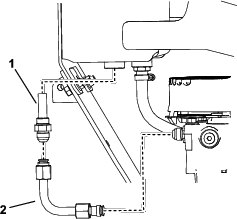
    6. Remove the tube and screen fitting from the tank and pump (Figure 12). Discard the screen fitting.
      g209573
    7. Install the new screen fitting to the tank (Figure 12). Torque the fitting to 79 to 98 N∙m (58 to 72 ft-lb)

    8. Install the tube to the screen fitting and pump (Figure 12).

    9. Torque the ends of the tube to 45 to 56 N∙m (33 to 41 ft-lb).

    10. Remove the hydraulic filter (Figure 11).

    11. Lubricate the new filter gasket and fill the filter with hydraulic fluid.

    12. Ensure that the filter-mounting area is clean and screw the filter on until the gasket contacts the mounting plate; then tighten the filter an additional 1/10 to 1/4 turn (Figure 11).

    13. Fill the hydraulic tank with fluid; refer to Checking the Hydraulic Fluid.

    14. Start the engine and let it run with an attachment connected for about 2 minutes to purge air from the system.

    15. Shut off the engine and check for leaks.

      Warning

      Hydraulic fluid escaping under pressure can penetrate skin and cause injury. Fluid injected into the skin must be surgically removed within a few hours by a doctor familiar with this form of injury; otherwise, gangrene may result.

      • Keep your body and hands away from pinhole leaks or nozzles that eject high-pressure hydraulic fluid.

      • Use cardboard or paper to find hydraulic leaks; never use your hands.

    Close section

    Cleaning Debris from the Hydraulic Cooler

    1. Park the machine on a level surface, disengage the PTO, engage the parking brake, and move the motion-control levers outward to the NEUTRAL-LOCK position.

    2. Shut off the engine and remove the key.

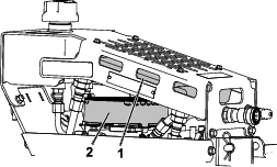
    3. Remove any debris buildup from the hydraulic cooler and pump fan shroud (Figure 13).

      Note: You may use pressurized air to help remove debris that are difficult to reach.
      g209576
    Close section

    Replacing the Belt

    Signs of a worn belt include squeaking when the belt is rotating, a frayed belt edge, burn marks, and cracks. Replace the deck belt if any of these conditions are evident.

    1. Park the machine on a level surface, disengage the PTO, engage the parking brake, and move the motion-control levers outward to the NEUTRAL-LOCK position.

    2. Shut off the engine and remove the key.

    3. Remove the belt from the pulleys (Figure 14).
      g209259
    4. Install the new belt around the machine clutch pulley, idler pulley, and high-flow pump pulley (Figure 14).

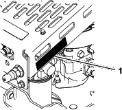
      Note: Use care not to cut or twist the belt as you slide it under the pump pulley and frame. You do not need to remove the spring from the idler pulley.

    Close section
    Close section