CALIFORNIA
Proposition 65 Warning
This product contains a chemical or chemicals known to the State of California to cause cancer, birth defects, or reproductive harm.
The engine exhaust from this product contains chemicals known to the State of California to cause cancer, birth defects, or other reproductive harm.
Note: Retain all removed components and fasteners unless otherwise specified.
Important: If your machine has a groomer installed, you must equip the machine with the Extended Axle Kit (Part No. 136-7287) to ensure a proper fit with the trailer.
Unlock and lower the trailer ramp.
Remove the cap screw (3/8 x 2-1/2 inch), spacer, washer, and locknut securing a load ramp to the rear of each tube assembly (Figure 1).
Remove the flange-head screws (5/16 x 3/4 inch) and flange nuts securing each locking bracket to the ramp (Figure 1)
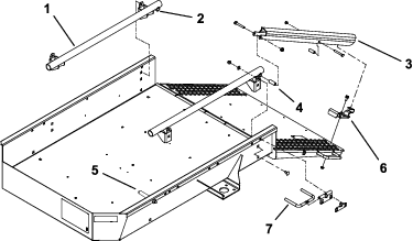
Remove the cap screw and nut securing the trailer stop to each side of trailer (Figure 1).
Remove the 4 carriage bolts, flat washers, and locknuts securing the tube assembly mounting brackets to each side of the trailer (Figure 1).
Remove the wheel rods and brackets from each side of trailer (Figure 1).
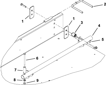
Install each tube assembly to a trailer side with 4 wall stiffeners, 4 carriage bolts (3/8 x 2-1/4 inches), 2 spacers and 2 locknuts (Figure 2). Position the tube assemblies so that the small cross tubes are to the rear.
Important: If your machine is equipped with a groomer, install the spacers only on the right side of the trailer; the left tube assembly must connect directly to the trailer wall.
Install the trailer stops and new spacers to the front of the tube assemblies with the cap screws and nuts previously removed. Position the components as shown in Figure 2.
Note: Tube assemblies built prior to 2006 do not have the trailer stop mounting holes drilled in them. Locate and drill the holes as follows:
Measure in 4.5 cm (1 3/4 inches) from the front end of each tube assembly.
Drill a 10.4 mm (0.41 inch) diameter hole through the top and the bottom of the tube. Make sure that the hole is centered on the tube.
Mount a load ramp to the rear of each tube assembly with a cap screw (3/6-16 x 2-1/2 inches), spacer, washer, and locknut (Figure 1).
Position a locking bracket onto each side of the ramp so that they align with the underside of the load ramps, engage with coated pins in the load ramps, and align with the holes in the ramp (Figure 1 and Figure 3). Use only 1 set of mounting holes per locking bracket.
Loosely mount each locking bracket to the ramp with flange-head screws (5/16-18 x 3/4 inch) and flange nuts (Figure 1 and Figure 3).
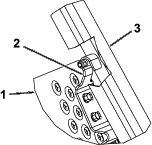
Raise and lock the ramp. Adjust the locking brackets so that they are engaged on the pins, and tighten the flange screws and nuts (Figure 1 and Figure 3).
Mount the new, longer wheel rods to the front and rear sets of mounting holes in each side of trailer, using brackets and fasteners previously removed (Figure 1 and Figure 2).