CALIFORNIA
Proposition 65 Warning
Hydraulic fluid escaping under pressure can penetrate skin and cause injury.
Make sure that all hydraulic fluid hoses and lines are in good condition and all hydraulic connections and fittings are tight before applying pressure to the hydraulic system.
Keep your body and hands away from pin-hole leaks or nozzles that eject high-pressure hydraulic fluid.
Use cardboard or paper to find hydraulic leaks.
Safely relieve all pressure in the hydraulic system before performing any work on the hydraulic system.
Seek immediate medical attention if fluid is injected into skin.
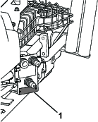
Whenever you need service, genuine Toro parts, or additional information, contact an Authorized Service Dealer or Toro Customer Service and have the model and serial numbers of your product ready. Figure 1 identifies the location of the model and serial numbers on the product. Write the numbers in the space provided.
Note: Determine the left and right sides of the machine from the normal operating position.
 |
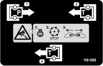
Safety decals and instructions are easily visible to the operator and are located near any area of potential danger. Replace any decal that is damaged or missing. |
Park the machine on a level surface.
Lower the attachments.
Engage the parking brake.
Shut off the engine and remove the key.
Thoroughly clean the machine. Remove all debris to ensure that the mounting brackets will fit properly and that no dirt or debris gets into the hydraulic system.
Thoroughly clean the area around the air cleaner.
Loosen the radiator clamp around the hose and lower the clamp onto the hose.
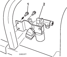
Remove the inside bolt holding the air cleaner in place.
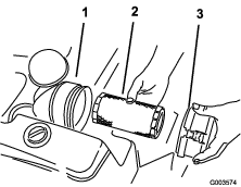
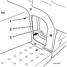
Remove the air-cleaner cover and filter (Figure 2).
Remove the hose from the air-cleaner canister.
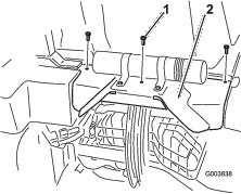
Spread the air-cleaner strap open and pull it over the end of the canister where the filter was taken out (Figure 3).
Cover the hose or insert a rag into it so that no dirt or debris gets into it while installing this kit.
Remove the opposite bolt holding the air-cleaner strap to the machine frame.
Drain the hydraulic tank. Refer to the machine Operator's Manual.
Raise the rear of the machine off the ground and block up the rear of the machine. Refer to the machine Operator's Manual under Raising the Machine.
Mechanical or hydraulic jacks may fail to support the machine and cause serious injury.
Use jack stands when supporting the machine.
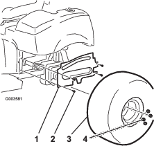
Remove the left rear tire.
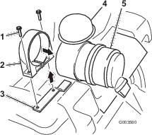
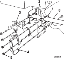
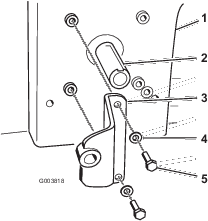
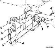
Remove the 4 flange-head screws securing the left wheel shroud to the frame (Figure 4). Remove and retain the shroud.
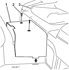
Remove the 2 flange-head screws securing the left front screen to the frame. Remove and retain the screen.
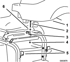
Remove the 3 bolts securing the rear hitch shield to the frame.
Remove the 2 screws securing the center shroud to the frame (Figure 7). Remove and retain the shroud.
Disconnect the hydraulic lines going to the tank.
Remove the top hydraulic tank bracket from the machine frame and loosen the 2 brackets on the side of the frame (Figure 8). Remove the tank and retain the hardware.
Parts needed for this procedure:
| Small 90-degree tee with barb | 1 |
| Large 90-degree elbow (threaded both ends) | 1 |
| Strainer | 1 |
Note: Make sure that all O-rings are lubricated and properly positioned on all fittings before installation.
Note: Install all fittings and hydraulic lines loosely first and then tighten them when everything is installed. Install the fittings at the angles shown in the figures.
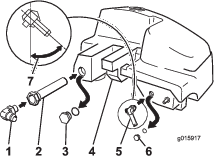
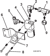
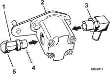
Remove the 2 hydraulic tank plugs from the side of the tank.
Install the strainer into the hydraulic tank where the large plug was removed.
Install the large 90-degree elbow into the strainer.
Install the small 90-degree tee with barb where the small plug was removed (Figure 9).
Parts needed for this procedure:
| Retainer bracket | 1 |
| Muffler clamp | 2 |
| Hose-retainer bracket | 1 |
| Coupler bracket | 1 |
Note: Install all hydraulic lines loosely first and then tighten them when everything is installed.
Position the clamps around the round tube of the rear frame.
Install the hose-retainer bracket and the coupler bracket to the muffler clamps.
Note: Do not tighten the nuts at this time. The coupler bracket needs to be loose to install the hydraulic lines (Figure 10).
Temporarily position the coupler bracket on the round frame tube; refer to Figure 11.
Note: Place the coupler bracket where the tube begins to bend.
Parts needed for this procedure:
| Valve | 1 |
| Valve plate | 1 |
| Bolt (1/4 x 1-3/4 inches) | 2 |
| Nut (1/4 inch) | 2 |
| Small 90-degree elbow | 1 |
| Tee fitting | 1 |
| Thread-forming screw (9/32 x 3/4 inch) | 2 |
| Tee adapter | 1 |
| Relay | 1 |
| Cap | 1 |
Note: Make sure that all O-rings are lubricated and properly positioned on all fittings before installation.
Note: Install all fittings and hydraulic lines loosely first and then tighten them when everything is installed. Install the fittings at the angles shown in the figures.
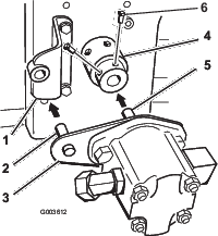
Install the fittings at the angles shown in the figures. Install the tee fitting to the side of the valve. Refer to Figure 12 for the correct tee fitting.
Install a small 90-degree elbow to the top of the valve (Figure 12).
Install the tee adapter to the 90-degree elbow. Refer to Figure 12 for the correct tee fitting.
Install the cap onto the tee adapter (Figure 12).
Install the relay to the valve bracket at the same time the valve is installed to the valve bracket.
Install the valve to the valve bracket with 2 bolts (1/4 x 1-3/4 inches) and 2 nuts (1/4 inch); refer to Figure 12.
Install the valve bracket to the machine frame with 2 thread-forming screws (9/32 x 3/4 inch); refer to Figure 13.
Parts needed for this procedure:
| Hydraulic cap | 1 |
| Hydraulic line number 1 | 1 |
| Hydraulic line number 2 | 1 |
| Hydraulic line (hose) number 5 | 1 |
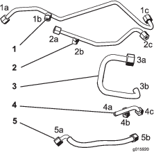
Use Figure 14 for identifying the correct hydraulic lines.
Note: Install all hydraulic lines loosely first and then tighten them when everything is installed.
Install the hydraulic cap onto hydraulic line number 1, port 1b.
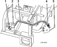
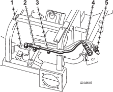
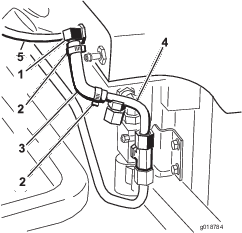
Position hydraulic line number 1 into the machine as shown in Figure 15.
Install hydraulic line number 1 to the tee fitting assembled to the side of the valve (Figure 15).
Install the hydraulic line number 1 to the upper male coupler (Figure 15).
Position hydraulic line number 2 into the machine as shown in Figure 16.
Install hydraulic line number 2 to the tee fitting assembled to the 90-degree elbow and the top of the valve (Figure 16).
Install hydraulic line number 2 to the upper female coupler (Figure 16).
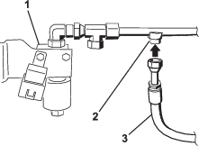
Loosely install hydraulic line (hose) number 5 to the lower male coupler (Figure 17).
Note: The other end of this hose will be installed in Procedure 10.
Parts needed for this procedure:
| Hydraulic pump | 1 |
| 45-degree fitting (male ends) | 1 |
| Hub assembly | 1 |
| Square key (1/4 x 1 inch) | 1 |
| Setscrew (5/16 x 3/4 inch) | 4 |
| Pump bracket | 1 |
| Bolt (with thread-locking compound) (5/16 x 3/4 inch) | 2 |
| Washer (3/8 inch) | 2 |
| Large 90-degree elbow (with hose barbed end) | 1 |
Install the large square 90-degree elbow to the side of the hydraulic pump.
Install the 45-degree elbow to the side of the hydraulic pump (Figure 18).
Remove the existing cover over the engine PTO (power takeoff).
Install the pump bracket to the engine with 2 bolts (5/16 x 3/4 inch) and 2 washers (3/8 inch). Refer to Figure 19 for the correct position to install the pump bracket.
Apply anti-seize compound to the engine PTO (power takeoff) shaft and the hydraulic motor shaft.
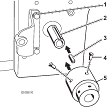
Install the square key (1/4 x 1 inch) into the slot in the engine PTO shaft (Figure 20).
Align the hub assembly with the square key and install it onto the engine PTO (power takeoff) shaft (Figure 20).
Note: Make sure that the hub assembly is totally bottomed out on the shaft.
Apply removable thread-locking compound to the 2 setscrews (5/16 x 3/4 inch) and install them into the hub assembly to secure it to the PTO shaft (Figure 20).
Install the pump plate stud into the pump bracket while installing the hydraulic pump shaft into the hub assembly.
Note: The hydraulic pump shaft will touch the end of the engine PTO shaft (Figure 21).
The hub assembly needs to be totally seated on the shaft.
Note: Verify that there is a gap between the pump plate and the hub assembly. If there is no gap, then the hub assembly is not installed correctly and needs to be seated correctly (Figure 22).
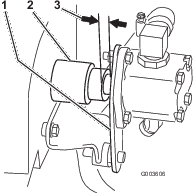
Apply removable thread-locking compound to the 2 setscrews (5/16 x 3/4 inch) and install them into the hub assembly to secure the hydraulic pump shaft (Figure 21).
Parts needed for this procedure:
| Hydraulic line number 3 | 1 |
| Hydraulic line number 4 | 1 |
Note: Install all hydraulic lines loosely first and then tighten them when all everything is installed.
Use Figure 23 as a key for identifying the correct hydraulic lines.
Install the existing hoses back onto the hydraulic tank.
Install the hydraulic tank to the frame and secure it with the 3 brackets previously removed and loosened (Figure 24).
Install hydraulic line number 4 to the tee fitting assembled to the side of the valve (Figure 25).
Position hydraulic line number 3 into the machine as shown in Figure 26.
Install hydraulic line number 3 to the large 90-degree elbow installed to the strainer and hydraulic tank (Figure 26 and Figure 31).
Parts needed for this procedure:
| Large hydraulic hose | 1 |
| Hydraulic hose with fittings | 1 |
| Large hose clamp | 2 |
| Small hose clamp | 2 |
| Small molded hydraulic hose | 1 |
| R-clamp | 1 |
| Bolt (5/16 x 7/8 inch) | 1 |
| Flange nut (5/16 inch) | 1 |
Note: Make sure that nothing rubs against any hoses.
Slide the 2 large hose clamps onto the large hydraulic hose.
Install the large hydraulic hose to the 90-degree elbow installed to the side of the hydraulic pump (Figure 27 and Figure 31).
Tighten a hose clamp around the hose and elbow (Figure 27).
Install the large hydraulic hose to hydraulic line number 3 (Figure 27).
Tighten the hose clamp around the hose and hydraulic line number 3 (Figure 27).
Install an R-clamp onto the large hydraulic hose as shown in Figure 28.
Install the R-clamp to the retainer bracket with a bolt (5/16 x 7/8 inch) and a nut (5/16 inch); refer to Figure 28.
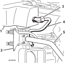
Install the hydraulic hose with fittings to the fitting on hydraulic line number 2 as shown in Figure 29.
Install the hydraulic hose with fittings to the 45-degree elbow attached to the hydraulic pump (Figure 30 and Figure 31).
Note: It will be below the hydraulic cylinder.
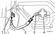
Refer to Figure 31 for the correct locations of the hoses and hydraulic lines to the hydraulic pump.
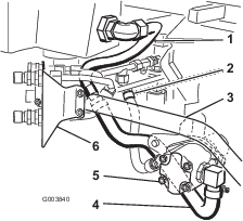
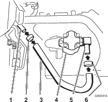
Slide the 2 small hose clamps onto the small molded hydraulic hose (Figure 32).
Install the long leg of the molded hose onto the 90-degree tee in the hydraulic tank (Figure 32).
Install the short leg of the molded hose onto the barb end of hydraulic line number 4 (Figure 32).
Tighten the two small hose clamps on each end of the molded hose.
Loosely install the hydraulic line (hose) number 5 to the small 90-degree tee (Figure 32).
Note: Make sure that the hoses and hydraulic lines are routed away from and to do not rub against any sharp, hot, or moving components.
When all hydraulic lines and hoses are installed, tighten all of the connections.
Note: Use a backup wrench on all tank fittings.
Position the coupler bracket as close to the left tire as possible and tighten the clamps.
Parts needed for this procedure:
| Harness | 1 |
| Switch | 1 |
| Fuse | 1 |
Remove the control panel from the machine.
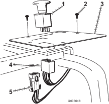
Remove the plastic plug from the panel and install the switch to the panel (Figure 35).
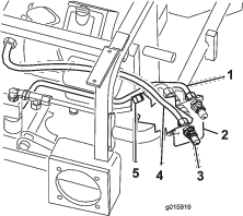
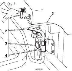
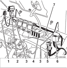
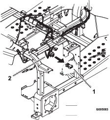
Route the harness along the seat hinge from the switch and to the relay previously installed to the valve (Figure 33).
Install the harness to the switch in the control panel (Figure 35).
Remove the jumper wire from the main harness under the control panel (Figure 34).
Install the main harness connector to the main harness (Figure 35).
Install the control panel to the machine.
Install the fuse into right slot in the fuse block (Figure 33).
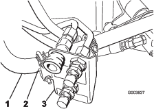
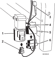
Install the square connector to the relay installed next with the valve (Figure 36).
Install the small connector to the valve (Figure 36).
Fasten the wire harness to the valve with a cable tie.
Parts needed for this procedure:
| Dipstick | 1 |
| Hydraulic fluid | 25.5 L (6-3/4 US gallons) |
The hydraulic system capacity is now 25.5 L (6-3/4 US gallons).
Refer to the Operator's Manual for the correct fluid to use.
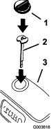
Remove the old dipstick from the hydraulic tank and discard.
Slowly pour approximately 80% of the specified fluid into the tank.
Insert the new dipstick and check the level of the hydraulic fluid (Figure 37).
Slowly add the additional fluid to bring it to the Full mark.
Start the machine and let it run for 5 minutes.
Check for any leaks in the system with a piece of cardboard.
Hydraulic fluid escaping under pressure can penetrate skin and cause injury.
If hydraulic fluid is injected into the skin it must be surgically removed within a few hours by a doctor familiar with this type of injury. Gangrene may result if this is not done.
Keep body and hands away from pin-hole leaks or nozzles that eject high-pressure hydraulic fluid.
Use cardboard or paper to find hydraulic leaks.
Safely relieve all pressure in the hydraulic system before performing any work on the hydraulic system.
Make sure that all hydraulic-fluid hoses and lines are in good condition and that all hydraulic connections and fittings are tight before applying pressure to the hydraulic system.
Install the left front screen to the frame.
Install the front shroud to the frame with 4 flange-head screws.
Install the 4 flange-head screws securing the left wheel shroud to the frame (Figure 38).
Install the left rear tire (Figure 38).
Lower the machine onto the ground.
Install the rear hitch shield.
Install the air-cleaner assembly.