CALIFORNIA
Proposition 65 Warning
Note: Determine the left and right sides of the machine from the normal operating position.
Park the machine on a level surface.
Engage the parking brake.
Shut off the engine and remove the key.
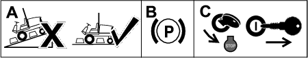
Open the hood.
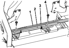
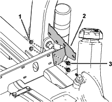
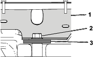
Behind the seat, cut the cable ties securing the hose to the heat shield and remove the 2 bolts (1/4 x 1/2 inch) as shown in Figure 2. Remove the heat shield and retain the bolts.
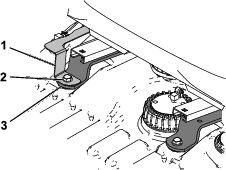
Remove and retain the 2 front seat bolts and washers, unplug the wire harness under the seat, and remove the seat (Figure 3).
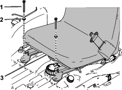
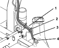
Remove the vent strap and retain the bolt (Figure 4).
Disconnect the left fuel hose from the fitting near the filler neck and tee fitting (Figure 4).
Note: If fuel comes out when you disconnect the hose, connect it, drain the fuel tank, and disconnect the hose again.
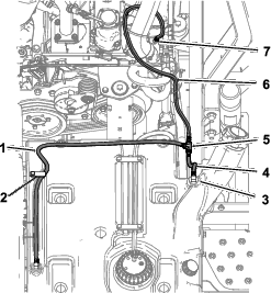
Disconnect the rear fuel hose from the engine manifold port and tee fitting (Figure 4).
Disconnect the right fuel hose from the front fitting on the right side of the fuel tank and the tee fitting (Figure 4).
Parts needed for this procedure:
| Fuel vent tube | 1 |
| Heat shield | 1 |
| Fuel-line bracket | 1 |
| Tee fitting | 1 |
| Straight fitting | 2 |
| 90-degree fitting | 1 |
| Hose (1/4 x 3 inches) | 1 |
| Small bracket | 1 |
| Right hose (1/4 x 54-1/4 inches) | 1 |
| Left hose (1/4 x 19 inches) | 1 |
| Rear hose (3/16 x 53 inches) | 1 |
| Hose clamp (13/32 inch) | 1 |
| Hose clamp (1/2 inch) | 7 |
| Large R-clamp | 1 |
| Small R-clamp | 1 |
| Cable tie | 14 |
| Bolt (1/4 x 1/2 inch) | 2 |
| Nut (1/4 inch) | 2 |
| Clip | 1 |
| Bolt (1/4 x 5/8 inch) | 2 |
Loosely install the fuel-line bracket using 1 bolt (3/8 x 3 inches), 1 washer, and 1 bolt (1/4 x 1/2 inch) that you removed previously (Figure 5).
Note: You will also use the hardware to install the seat later.
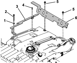
Loosely install the heat shield using 2 bolts (3/8 x 1 inch) that you removed previously (Figure 5).
Install the small bracket to the heat shield using 2 bolts (1/4 x 1/2 inch) and 2 nuts (1/4 inch) as shown in Figure 6. Torque the bolts to 1017 to 1243 N∙cm (90 to 110 in-lb).
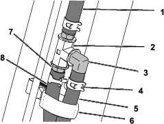
Install the fuel vent tube to the left side of the roll bar using the small R-clamp and bolt (1/4 x 5/8 inch) as shown in Figure 7. Torque the bolt to 1017 to 1243 N∙cm (90 to 110 in-lb).
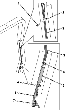
Install a hose (3 inch) to the fuel vent tube using a hose clamp (1/2 inch) as shown in (Figure 7.
Connect the hose to the tee fitting using a straight fitting and hose clamp (1/2 inch) as shown in Figure 7.
Loosely install the clip, large R-clamp, and bolt (1/4 x 5/8 inch) as shown in Figure 8.
Connect the left hose (1/4 x 54-1/4 inches) to the front fitting using a hose clamp (1/2 inch) as shown in Figure 9.
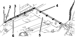
Route the hose along the fuel-line bracket and along the rear of the heat shield (Figure 9).
Route the hose through the large R-clamp and connect it to the tee fitting using a straight fitting and a hose clamp (1/2 inch) as shown in Figure 10.
Secure the hose to the brackets using 8 cable ties (3 on the fuel-line bracket and 5 on the heat shield) as shown in Figure 9.
Note: Keep the hose as close to the brackets as possible so that there is no slack for fuel to become trapped in the hose.
Connect the left hose (1/4 x 19 inches) to the fitting near the filler neck using a hose clamp (1/2 inch) as shown in Figure 11.
Route the hose along the small bracket, up the roll bar, through the large R-clamp, and to the tee fitting. Connect the hose to the tee fitting using a 90-degree fitting and hose clamp (1/2 inch) as shown in Figure 10.
Torque the bolt securing the large R-clamp (Figure 10) to 1017 to 1243 N∙cm (90 to 110 in-lb).
Secure the hose to the small bracket using 2 cable ties (Figure 11).
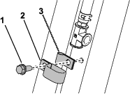
Connect the rear hose (3/16 x 53 inches) to the fuel vent line using a hose clamp (1/2 inch) as shown in Figure 12.
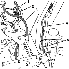
Route the hose down the roll bar, then up to the engine manifold port. Connect it to the port using a hose clamp (13/16 inch) as shown in Figure 12.
Secure the hose to engine hoses using 2 cable ties (Figure 12).
Secure all 3 hoses to the small bracket using 2 cable ties (Figure 12).
Remove the 2 bolts from the heat shield and the front bolt and washer from the fuel-line bracket (Figure 5).
Torque the rear bolt (1/4 x 1/2 inch) on the fuel-line bracket (Figure 5) to 1017 to 1243 N∙cm (90 to 110 in-lb).
Place the seat on the fuel tank so that the seat brackets are between the kit brackets and the fuel tank (Figure 11 and Figure 12). Connect the wire harness to the seat.
Secure the front of the seat brackets using 2 bolts (3/8 x 3 inches) and 2 washers (Figure 13).
Secure the rear of the seat brackets using 2 bolts (3/8 x 1 inch) as shown in Figure 14.
Torque the 4 bolts to 37 to 45 N∙m (27 to 33 ft-lb).
Close the hood.