Safety
Warning
CALIFORNIA
Proposition 65 Warning
Use of this product may cause exposure to chemicals known to the State of California to cause cancer, birth defects, or other reproductive harm.
Rollover Protection System (ROPS) Safety
-
Do not remove the ROPS from the machine.
-
Ensure that the seat belt is attached and that you can release it quickly in an emergency.
-
Check carefully for overhead obstructions and do not contact them.
-
Keep the ROPS in safe operating condition by thoroughly inspecting it periodically for damage and keeping all the mounting fasteners tight.
-
Replace a damaged ROPS. Do not repair or alter it.
-
The ROPS is an integral safety device.
-
Always wear your seat belt.
Safety and Instructional Decals
 |
Safety decals and instructions are easily visible to the operator and are located near any area of potential danger. Replace any decal that is damaged or missing. |

Installation
Preparing the Machine
-
Park the machine on a level surface.
-
Engage the parking brake.
-
Shut off the engine and remove the key.

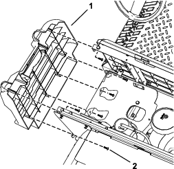
Removing the Seat Assembly
-
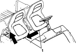
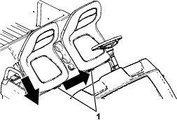
Push the seat assembly forward to the raised position.
-
Slide the seat assembly to the side out of the pins, and lift the seat assembly upward (Figure 2).
Removing the Handholds
Removing the Side Panels
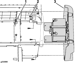
For Electric Machines
-
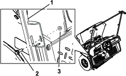
Remove the charger and the charger cable from the charger bracket (Figure 5).
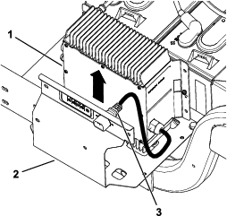
-
Use a T30 socket wrench to remove the 4 torx-head screws (M6.0 x 22 mm) securing the charger bracket to the left side panel (Figure 6).
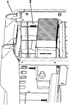
-
Use a T30 socket wrench to remove the 4 torx-head screws (M6.0 x 22 mm) from the left side panel and remove it (Figure 7).
-
Repeat step 3 on the right side.
-
Disconnect the batteries; refer to your machine Operator’s Manual.
Note: Correctly follow the procedure for disconnecting the batteries. Disconnect the main-negative battery cable (black), then disconnect the main positive-battery cable (red).
For Gasoline Machines
-
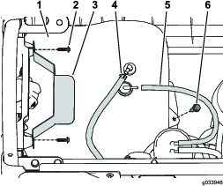
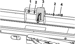
Disconnect the vent tube and fuel line from the fuel tank (Figure 8).
Danger
In certain conditions, fuel is extremely flammable and highly explosive. A fire or explosion from fuel can burn you and others and can damage property.
-
Drain fuel from the fuel tank when the engine is cold. Do this outdoors and in an open area. Wipe up any fuel that spills.
-
Never smoke when handling fuel, and stay away from an open flame or where fuel fumes may be ignited by a spark.
-
-
Remove the 2 screws securing the hold-down to the left side panel, and remove the hold-down (Figure 8).
-
Remove flange bolt securing the fuel tank to the fuel-tank tray and remove the fuel tank (Figure 8).
-
Use a T30 socket wrench to remove the 6 torx-head screws (M6.0 x 22 mm) from the left side panel and remove the side panel (Figure 9).
-
Disconnect the negative (–) battery cable from the battery and then the positive (+) battery cable as shown in Figure 10.
-
Remove the 2 flange-head bolts (5/16 x 3/4 inch) that secure the battery tray to the frame and use a T30 socket wrench to remove the 4 torx-head screws (M6.0 x 22 mm) that secure the right side panel, and remove the right side panel (Figure 11).
Note: The battery comes off with the right side panel as shown in Figure 11.
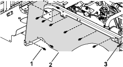
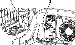
Removing the Rubber Covers
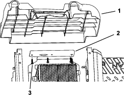
Remove the 10 plastic rivets and the cable tie from each rubber cover and remove the rubber covers (Figure 12).
Drilling the Holes for the ROPS Brackets
-
Align a ROPS bracket with the 2 holes behind the seat base and the hole toward the front of the frame rail as shown in Figure 13.
-
Using a clamp, secure the ROPS bracket in place.
-
Mark the hole locations on the ROPS bracket (Figure 13).
-
Using a ROPS bracket as a guide, drill 3 holes (13.5 mm or 17/32 inch) into the frame (Figure 14).
Caution
Use caution when drilling the holes into the right side of the frame on an electric machine.
If you drill too far, you could damage the batteries or other components.
-
Repeat this procedure on the other side.
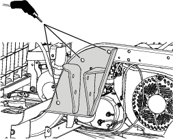
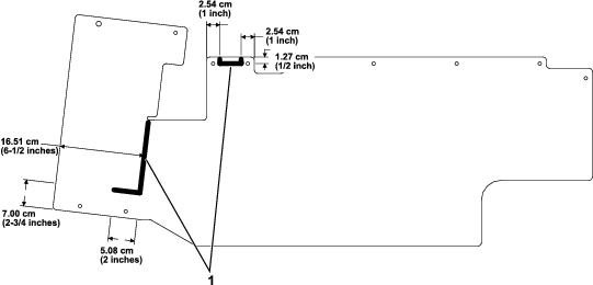
Cutting the Rubber Covers
Cut the rubber covers using the measurements shown in Figure 15.
Note: The cuts in the rubber cover allow for space to install the ROPS brackets.
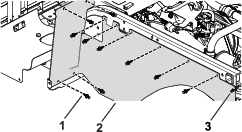
Installing the Rubber Covers
Parts needed for this procedure:
| Cable tie | 2 |
| Plastic rivets | 4 |
Install each rubber cover using the previously removed 10 plastic rivets and a cable tie (Figure 16).
If the previously removed rivets are damaged or missing, replace them with the rivets provided in this kit.
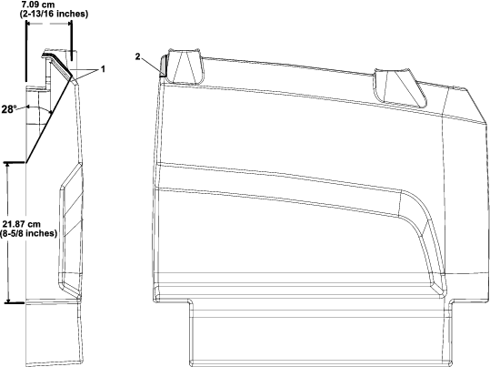
Trimming the Side Panels
Trim the side panels using the measurements shown in Figure 17.
Installing the ROPS Brackets
Parts needed for this procedure:
| Left ROPS bracket | 1 |
| Right ROPS bracket | 1 |
| Flange-head bolt (1/2 x 3 inches) | 6 |
| Flat washer (1/2 inch) | 10 |
| Locknut (1/2 inch) | 6 |
-
Install a ROPS bracket using 3 flange-head bolts (1/2 x 3 inches), 5 flat washers (1/2 inch), and 3 locknuts (1/2 inch) as shown in Figure 18.
Note: Ensure that you install the 2 flat washers (1/2 inch) on the outside as shown in Figure 18.
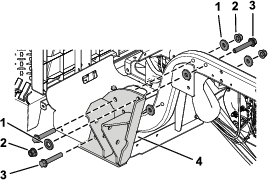
-
Torque the 3 flange-head bolts (1/2 x 3 inches) to 94 to 108 N∙m (70 to 80 ft-lb).
-
Repeat this procedure on the other side.
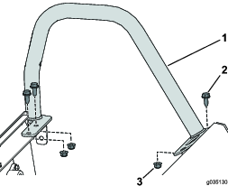
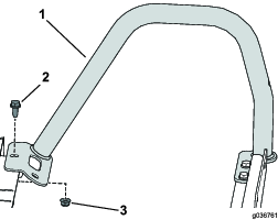
Installing the Roll Bar
Parts needed for this procedure:
| Roll bar | 1 |
| Flange-head bolt (1/2 x 3-1/2 inches) | 4 |
| Locknut (1/2 inch) | 4 |
Note: Have an assistant help you to raise the roll bar into position.
-
Secure 1 side of the roll bar to a ROPS bracket using 2 flange-head bolts (1/2 x 3-1/2 inches) and 2 locknuts (1/2 inch) as shown in Figure 19.
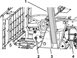
-
Torque the 2 flange-head bolts (1/2 x 3-1/2 inches) to 94 to 108 N∙m (70 to 80 ft-lb).
-
Repeat this procedure on the other side.
Installing the Side Panels
For Electric Machines
-
Install the left side panel using the previously removed 4 torx-head screws (M6.0 x 22 mm) as shown in Figure 7.
-
Secure the charge bracket to the left side panel using the previously removed 4 torx-head screws (M6.0 x 22 mm) as shown in Figure 6.
-
Secure the charger and the charger cable to the charger bracket (Figure 5).
-
Repeat step 1 on the right side.
-
Connect the battery; refer to your machine Operator's Manual.
Note: Correctly follow the procedure for connecting the batteries. Connect the main positive-battery cable (red), then connect the main negative-battery cable (black).
For Gasoline Machines
-
Install each side panel using the previously removed torx-head screws (M6.0 x 22 mm) as shown in Figure 9 and Figure 11.
-
Secure the battery base on the right side using the previously removed 2 flange-head bolts (5/16 x 3/4 inch) as shown in Figure 11.
-
Connect the positive (+) battery cable to the battery using the bolt and nut (Figure 10).
-
Connect the negative (–) battery cable to the battery using the bolt and nut (Figure 10).
-
Secure the fuel tank to the fuel-tank tray using the previously removed flange bolt (Figure 8).
-
Secure the hold-down to the left side panel using the previously removed 2 screws (Figure 8).
-
Connect the vent tube and fuel line to the fuel tank (Figure 8).
Installing the Handholds
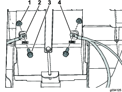
Installing the Seat Belts
Parts needed for this procedure:
| Seat belt | 2 |
| Seat latch | 2 |
| Hex-head bolt (7/16 x 1 inch) | 4 |
| Flat washer (7/16 inch) | 8 |
| Locknut (7/16 inch) | 4 |
-
Install a seat latch using a hex-head bolt (7/16 x 1 inch), 2 flat washers (7/16 inch), and a locknut (7/16 inch) as shown in Figure 20.
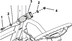
-
Torque the hex-head bolt (7/16 x 1 inch) to 68 to 81 N∙m (50 to 60 ft-lb).
-
Repeat steps 1 and 2 to install the other seat latch.
-
Install a seat belt using a hex-head bolt (7/16 x 1 inch), 2 flat washers (7/16 inch), and a locknut (7/16 inch) as shown in Figure 21.
-
Torque the hex-head bolt (7/16 x 1 inch) to 68 to 81 N∙m (50 to 60 ft-lb).
-
Repeat steps 4 and 5 to install the other seat belt.
Installing the Seat Assembly
Slide the seat assembly onto the pins and lower the seat assembly (Figure 22).
Installing the ROPS Extension
Parts needed for this procedure:
| Left windshield support | 1 |
| Right windshield support | 1 |
| Front support | 1 |
| Rear canopy support | 1 |
| Left, front mount bracket | 1 |
| Right, front mount bracket | 1 |
| Left, rear mount bracket | 1 |
| Right, rear mount bracket | 1 |
| Left, rear corner gusset | 1 |
| Right, rear corner gusset | 1 |
| Left, front corner gusset | 1 |
| Right, front corner gusset | 1 |
| Front crosslink | 1 |
| Crosslink tube | 2 |
| Flange nut (5/16 inch) | 28 |
| Nut (1/4 inch) | 2 |
| Hex-head flange bolt (1/4 x 1-1/2 inches) | 2 |
| Carriage bolt (5/16 x 1-3/4 inches) | 16 |
| Hex-flange bolt (5/16 x 1 inch) | 2 |
| Carriage bolt (5/16 x 2-3/4 inches) | 6 |
| Carriage bolt (5/16 x 1 inch) | 4 |
Note: Do not tighten any fasteners except when instructed.
-
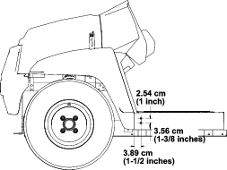
Using the dimensions shown in Figure 23, drill 2 holes (5/16 inch) into the outside of the floor plate on the left and right sides of the machine.
-
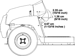
Using the dimensions shown in Figure 24, drill 1 hole (5/16 inch) into the outside of the footboard on the left and right sides of the machine.
-
Secure the middle bracket of the left and right windshield supports to the machine using 2 hex-flange bolts (5/16 x 1 inch) and 2 nuts (5/16 inch) in the holes you drilled (Figure 25).
-
Secure the lower bracket of the left and right windshield supports to the machine using 4 carriage bolts (5/16 x 1 inch) and 4 flange nuts (5/16 inch) in the holes you drilled in step 1 (Figure 26).
-
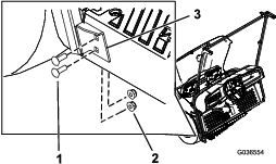
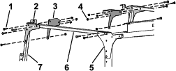
Use 2 carriage bolts (5/16 x 2-3/4 inches) and 2 flange nuts (5/16 inch) to secure the rear canopy support and the rear screen to the roll bar (Figure 27).
-
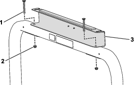
Use 4 carriage bolts (5/16 x 2-3/4 inches) and 4 nuts (5/16 inch) to secure the rear mount brackets and the rear corner gussets to the roll bar (Figure 28).
-
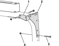
Loosely install the crosslink tubes to the rear mount brackets and rear corner gussets using 4 carriage bolts (5/16 x 1-3/4 inches) and 4 flange nuts (5/16 inch) as shown in Figure 29.
-
Loosely install the front mount brackets and front corner gussets to the crosslink tubes and the windshield supports using 8 carriage bolts (5/16 x 1-3/4 inches) and 8 flange nuts (5/16 inch) as shown in Figure 29.
-
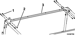
Loosely install the front crosslink to the front mount brackets and corner gussets using 4 carriage bolts (5/16 x 1-3/4 inches) and 4 flange nuts (5/16 inch) as shown in Figure 30.
-
Use 2 hex-head flange bolts (1/4 x 1-1/2 inches) and 2 nuts (1/4 inch) to secure the front support to the front crosslink (Figure 31).
-
Tighten all loose fasteners.
Installing the Canopy
Parts needed for this procedure:
| Sunshade | 1 |
| Clip | 2 |
| Sealing washer | 4 |
| Hex-flange bolt (1/4 x 1 inch) | 4 |
| Friction washer | 2 |
| Plastic washer | 4 |
| Flange bushing | 2 |
-
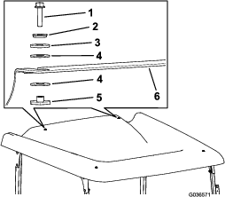
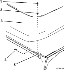
Install the sunshade to the front plates using 2 clips, 2 sealing washers, and 2 hex-flange bolts (1/4 x 1 inch) as shown in Figure 32.
Important: Apply thread-locking compound to the hex-flange bolts before installing.
-
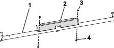
Install the sunshade to the rear crosslink using 2 hex-flange bolts (1/4 x 1 inch), 2 sealing washers, 2 friction washers, 4 plastic washers, and 2 flange bushings (Figure 33).
Important: Apply thread-locking compound to the hex-flange bolts before installing.
Important: Ensure that the plastic washers are installed onto the top and bottom of the sunshade, as this prevents damaging the sunshade.