CALIFORNIA
Proposition 65 Warning
Refer to your machine Operator’s Manual for maintenance safety information.
Move the machine to a level surface.
Release the blade-brake bail.
Disconnect the spark-plug wire from the spark plug.
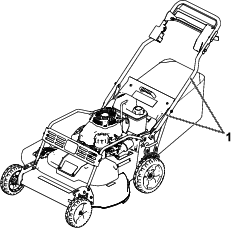
Remove the blade-drive system cover from the machine.
Tip the machine onto its side, with the air filter facing upward, until the upper handle rests on the ground.
Tipping the machine may cause the fuel to leak. Fuel is flammable and explosive, and can cause personal injury.
Run the engine dry or remove the fuel with a hand pump; never siphon the fuel.
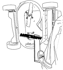
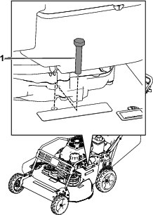
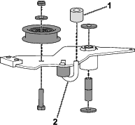
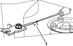
Use a block of wood to hold each blade steady (Figure 1).
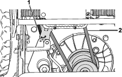
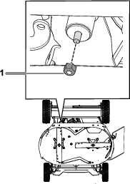
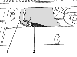
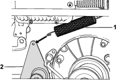
Remove the transmission belt and the transmission tension spring from the machine (Figure 2).
Note: Removing the transmission belt and the transmission tension spring allows access to the brake arm.
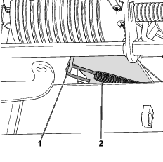
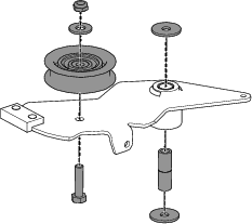
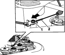
Remove the brake-extension spring from the brake arm (Figure 3).

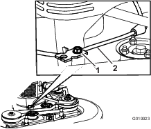
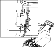
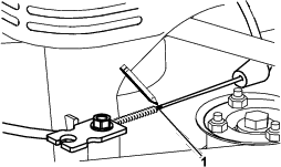
Remove the brake cable from the brake-arm hook (Figure 4).
Loosen the cable-clamp screw and slide the cable out from under the engine (Figure 5).
Remove the bolt and the nut that secures the brake arm onto the machine; retain and set the bolt and the nut aside (Figure 6 and Figure 7).
Remove the hardware from the brake arm (Figure 8).
Retain all hardware for use in Installing the Brake Arm and Brake Cable
Cut and remove the existing cable ties.
Disconnect the brake cable from the handle bracket (Figure 9).
Parts needed for this procedure:
| Brake arm | 1 |
| Brake cable | 1 |
| Rubber spacer | 1 |
| Cable tie | 2 |
Install the rubber spacer and the hardware from the old brake arm onto the new brake arm (Figure 10).
Important: Inspect the hardware for excessive wear. Replace the hardware if necessary.
Guide the rubber spacer along the hook until it is flush with the plate (Figure 10).
Torque the bolt that you previously removed in step 4 to 10 to 13 N∙m (85 to 115 in-lb).
Use the bolt and the nut that you previously removed in step to install the brake arm onto the machine (Figure 11 and Figure 12).
Torque the nut to 10 to 13 N∙m (85 to 115 in-lb).
Note: The brake arm should have a full range of motion.
Attach the brake cable to the handle bracket (Figure 13).
Route the brake cable through the insert below the cable clamp.
Attach the brake cable to the brake-arm hook (Figure 14).
Pull the cable jacket to remove slack (Figure 15).
Note: Do not put tension on the spring.
Mark the brake cable (Figure 16), then adjust the jacket until there is approximately 3 mm (1/8 inch) of slack (Figure 17).
Torque the cable-clamp screw to 11 to 14 N∙m (99 to 121 in-lb) to lock the adjustment in place.
Attach 2 cable ties at the indicated locations shown in Figure 18.
Attach the brake-extension arm to the brake arm (Figure 19).
Install the transmission belt and the transmission tension spring (Figure 20).
Install the blade-drive system cover.
Connect the spark-plug wire to the spark plug.