


Maintenance
Note: Determine the left and right sides of the machine from the normal operating position.
Important: When using the machine in conjunction with the Trans Pro 80, always use the stops on the trailer when servicing the machine. Overtipping can result in fuel spills. The stop on the Rail Ramp Kit requires inserting a broom handle or similar item through the holes behind the wheels.
Recommended Maintenance Schedule(s)
| Maintenance Service Interval | Maintenance Procedure |
|---|---|
| Before each use or daily |
|
| Every 50 hours |
|
| Every 100 hours |
|
| Every 500 hours |
|
| Every 1,000 hours |
|
| Before storage |
|
Important: Refer to your engine owner's manual for additional maintenance procedures.
Engine Maintenance
Servicing the Engine Oil
Fill the crankcase with approximately 0.6 L (20 fl oz) of the proper viscosity oil before starting. The engine uses any high-quality oil having the American Petroleum Institute (API) service classification SE or higher. Select the proper oil viscosity (weight) based on the ambient temperature. Figure 33 illustrates the temperature/viscosity recommendations.
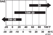
Note: Using multi-grade oils (5W-20, 10W-30 and 10W-40) will increase oil consumption. Check the oil level more frequently when using them.
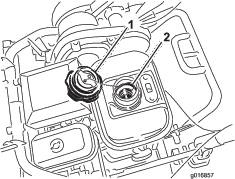
Checking the Engine-Oil Level
Note: The best time to check the engine oil is when the engine is cool, before it has been started for the day. If it has already been run, allow the oil to drain back down to the sump for at least 10 minutes before checking. If the oil level is at or below the L mark on the dipstick, add oil to bring the oil level to the H mark. Do not overfill. If the oil level is between the H and L marks, no oil addition is required.
-
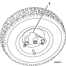
Remove the transport wheels (if installed).
-
Position the machine so that the engine is level.
-
Clean around the oil-level gauge (Figure 34)
-
Remove the oil-level gauge by rotating it counterclockwise (Figure 34).
-
Wipe the oil-level gauge clean and insert it into the filler port. Do not screw the gauge into the port. Then remove it and check the level of the oil. If the level is low, add only enough oil to raise the level until it is between the H and L marks on the gauge (Figure 35). Check the level of the oil. Do not overfill.

-
Install the oil-level gauge and wipe up any spilled oil.
Changing the Engine Oil
-
Start and run the engine for a few minutes to warm the engine oil.
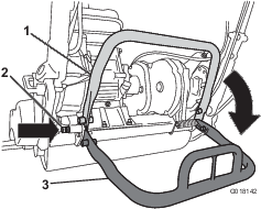
-
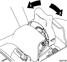
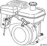
At the rear of the machine, place a drain pan under the drain plug (Figure 34). Loosen the drain plug.
-
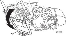
Push down on the handle to tip the machine and engine backward, allowing all the oil to run into the drain pan.
-
Install the drain plug and refill the crankcase with the specified oil.
-
Wipe up any spilled oil.
-
Dispose of the used oil properly. Recycle as per local codes.
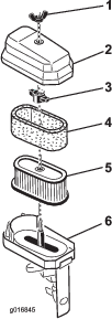
Servicing the Air Cleaner
-
Make sure that the wire is off the spark plug.
-
Remove the wing nut securing the air-cleaner cover to the air cleaner and remove the cover. Clean the cover thoroughly (Figure 36 and Figure 37).
-
If the foam element is dirty, remove it from the paper element (Figure 37). Clean it thoroughly.
-
Wash the foam element in a solution of liquid soap and warm water. Squeeze it to remove the dirt, but do not twist it because the foam may tear.
-
Dry by wrapping in a clean rag. Squeeze the rag and foam element to dry, but do not twist because the foam may tear.
-
Saturate the element with clean engine oil. Squeeze the element to remove the excess oil and to distribute the oil thoroughly.
Note: An oil damp element is desirable.
-
-
When servicing the foam element, check the condition of the paper element. Replace as required.
Note: Do not use compressed air to clean the paper element.
-
Install the foam element, paper element, and air-cleaner cover.
Important: Do not operate the engine without the air cleaner element because extreme engine wear and damage will result.
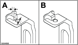
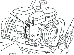
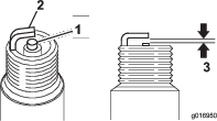
Servicing the Spark Plug
Use an NGK BR6HS spark plug or equivalent. The correct air gap is 0.6 to 0.7 mm (0.024 to 0.028 inch).
-
Pull the molded wire off the spark plug (Figure 38).
-
Clean around the spark plug and remove the plug from the cylinder head.
Important: Replace a cracked, fouled, or dirty spark plug. Do not sand blast, scrape, or clean the electrodes because engine damage could result from grit entering the cylinder.
-
Set the air gap at 0.6 to 0.7 mm (0.024 to 0.028 inch) as shown in Figure 39. Install the correctly gapped spark plug and tighten it firmly to 23 N∙m (17ft-lb).
Fuel System Maintenance
Cleaning the Fuel-Tank Screen
-
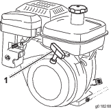
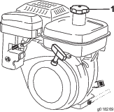
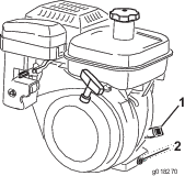
Unscrew and remove the fuel-tank cap from the fuel tank (Figure 40).
-
Remove the fuel-tank screen from inside the fuel tank.
-
Clean the screen in clean fuel and install it in the tank.
-
Install the fuel-tank cap to the fuel tank.
Replacing the Fuel Line
If fuel leaks from the fuel line, replace the line immediately.
Close sectionElectrical System Maintenance
Servicing the Traction Interlock Switch
Use the following procedure if the switch needs adjustment or replacement.
-
Make sure that the engine is off.
-
Remove the control panel.
-
Engage the traction lever.
-
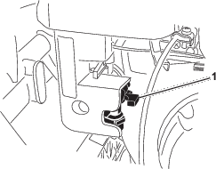
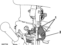
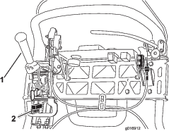
Loosen the interlock switch mounting fasteners (Figure 41).
-
Place a 1.6 mm (0.062 inch) thick shim between the traction lever and the interlock switch (Figure 41).
-
Tighten the interlock switch mounting fasteners.
-
Engage the traction lever and check the gap. The normal operating range is between 0.76 to 3.05 mm (0.03 to 0.12 inch). With the traction lever engaged, verify that the switch loses continuity. Replace the switch if required.
Servicing the Brake-Interlock Switch
-
Make sure that the engine is off.
-
Remove the control panel.
-
Engage the service-brake lever and engage the parking-brake latch.
-
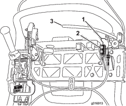
Loosen the interlock switch mounting fasteners (Figure 42).
-
Place a 1.6 mm (0.062 inch) thick shim between the parking-brake latch and the interlock switch (Figure 42).
-
Tighten interlock switch mounting fasteners. Check the gap. The latch must not contact the switch.
-
Engage the brake lever and rotate the latch. Verify that the switch loses continuity. Replace the switch if required.
Brake Maintenance
Adjusting the Service/Parking Brake
If the service/parking brake slips when operated, adjust the cable as follows:
-
Move the service/parking brake lever to the OFF position.
-
Remove the control panel.
-
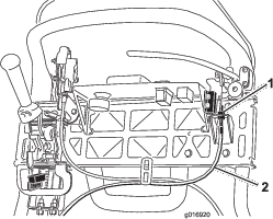
To increase the cable tension, loosen the upper cable jam nut and tighten the lower cable jam nut (Figure 43) until a force of 156 N (35 lb) applied to the brake lever handle is required to release the parking-brake latch. Do not over adjust it or the brake band may drag.
Belt Maintenance
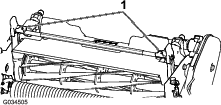
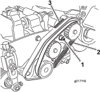
Inspecting the Reel-Drive Belt
-
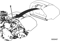
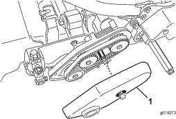
Loosen the flange bolt securing the belt cover and remove the belt cover to expose the belt (Figure 44).
-
To adjust the belt tension:
-
Loosen the bearing housing mounting nut (Figure 45).
-
Using a 16 mm (5/8 inch) wrench, rotate the bearing housing to make sure that it operates freely.
-
Clean any debris from inside the belt compartment and from around the compression spring (Figure 45).
-
Make sure that the compression spring is applying the proper tension on the belt.
-
Tighten the bearing housing mounting nut.
-
Install the belt cover.
-
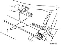
Visually Inspecting the Reel Clutch
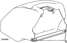
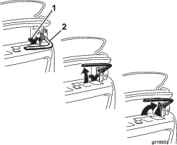
Remove the rubber plug (Figure 46) from the hole in the front of the transmission to visually inspect the reel clutch when making adjustments.
Important: Replace the plug when finished to prevent water and debris from contaminating the clutch.
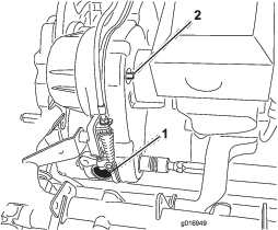
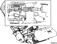
Engaging/Disengaging the Transmission-Belt Tensioner
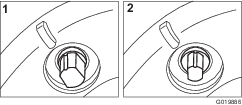
The transmission belt is tensioned by a spring loaded idler pulley. If the belt tension has to be engaged/disengaged, use a 3/8 inch wrench to rotate the engage/disengage shaft (Figure 46) to the desired position. Rotating the shaft 1/4 turn clockwise disengages the idler from the belt (Figure 47).
Note: The belt tension must be disengaged prior to removing the transmission cover.
Controls System Maintenance
Adjusting the Traction Control
If the traction control does not engage or slips during operation, the traction control may need adjusting.
-
Move the traction control to the ENGAGED position.
-
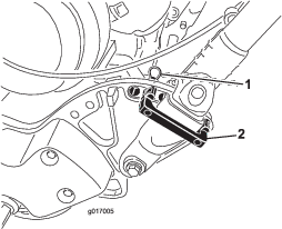
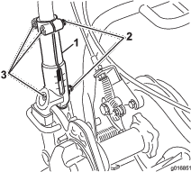
Measure the distance from the pin on either end of the traction-control spring (Figure 48); if it is not within 7.3 to 7.6 cm (2-7/8 to 3 inches), adjust the clutch according to the steps below.
-
Disengage the traction-control lever.
-
Loosen the jam nut on the turnbuckle and remove the clevis pin, disconnecting the spring from the turnbuckle (Figure 48).
-
Turn the turnbuckle in or out to adjust the length as needed.
-
Install the turnbuckle to the spring using the clevis pin.
-
Move the traction control to the ENGAGED position.
-
Measure the distance from the pin on either end of the traction-control spring (Figure 48); repeat steps 1 through 6 until it is within 7.3 to 7.6 cm (2-7/8 to 3 inches).
-
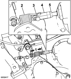
Adjusting the Reel Control
If the reel control does not properly engage, an adjustment is required.
-
Ensure that the reel control is disengaged.
-
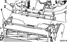
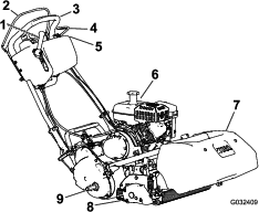
At the transmission bulkhead, adjust the reel-control cable (Figure 49) to attain a spring length of 70.6 to 72.4 mm (2.78 to 2.85 inches).
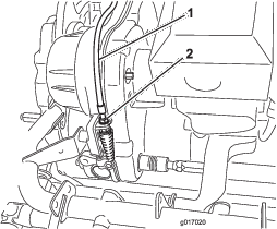
-
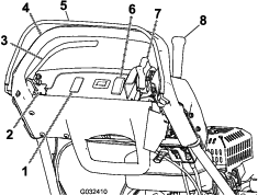
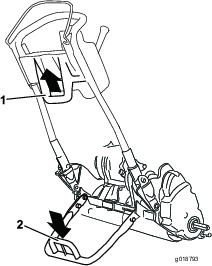
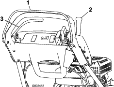
At the control handle bulkhead, loosen the reel-control cable until there is slack in the cable (Figure 50).
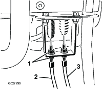
-
At the control handle bulkhead, tighten the reel-control cable enough to remove the slack from the cable without extending the spring.
-
Check the operation as follows:
-
Verify that the reel clutch teeth disengage when the clutch is released and the reel clutch teeth do not bottom out when engaged.
Note: Remove the rubber plug (Figure 46) from the hole in the front of the transmission to view reel clutch.
-
The reel stopping time must be less than 7 seconds with the reel to bedknife backed off.
-
Refer to the Service Manual or contact your authorized Toro distributor for further assistance.
-