| Maintenance Service Interval | Maintenance Procedure |
|---|---|
| Before each use or daily |
|
Introduction
This machine is a walk-behind, reel-blade lawn mower intended to be used by professional, hired operators in commercial applications. It is primarily designed for cutting grass on well-maintained lawns in parks, golf courses, sports fields, and on commercial grounds. It is not designed for cutting brush, mowing grass and other growth alongside highways, or for agricultural uses.
Read this information carefully to learn how to operate and maintain your product properly and to avoid injury and product damage. You are responsible for operating the product properly and safely.
You may contact Toro directly at www.Toro.com for product safety and operation training materials, accessory information, help finding a dealer, or to register your product.
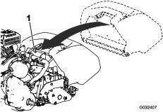
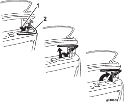
Whenever you need service, genuine Toro parts, or additional information, contact an Authorized Service Dealer or Toro Customer Service and have the model and serial numbers of your product ready. Figure 1 identifies the location of the model and serial numbers on the product. Write the numbers in the space provided.
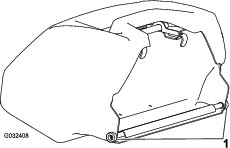
This manual identifies potential hazards and has safety messages identified by the safety-alert symbol (Figure 2), which signals a hazard that may cause serious injury or death if you do not follow the recommended precautions.

This manual uses 2 words to highlight information. Important calls attention to special mechanical information and Note emphasizes general information worthy of special attention.
This product complies with all relevant European directives; for details, please see the separate product specific Declaration of Conformity (DOC) sheet.
Warning
CALIFORNIA
Proposition 65 Warning
The engine exhaust from this product contains chemicals known to the State of California to cause cancer, birth defects, or other reproductive harm.
It is a violation of California Public Resource Code Section 4442 or 4443 to use or operate the engine on any forest-covered, brush-covered, or grass-covered land unless the engine is equipped with a spark arrester, as defined in Section 4442, maintained in effective working order or the engine is constructed, equipped, and maintained for the prevention of fire.
This spark ignition system complies with Canadian ICES-002.
Operating this machine between 1,524 to 2,438 m (5,000 to 8,000 ft) above sea level requires the high-altitude kit. See your Authorized Toro Dealer.
Safety
This machine has been designed in accordance with EN ISO 5395:2013 and ANSI B71.4-2012.
Improper use or maintenance by the operator or owner can result
in injury. To reduce the potential for injury, comply with these safety
instructions and always pay attention to the safety-alert symbol, which
means Caution, Warning, or Danger—personal safety instruction.
Failure to comply with the instruction may result in personal injury
or death.
Hazard control and accident prevention are dependent upon the awareness, concern, and proper training of the personnel involved in the operation, transport, maintenance, and storage of the machine. Improper use or maintenance of the machine can result in injury or death. To reduce the potential for injury or death, comply with the following safety instructions.
Safe Operating Practices
Training
-
Read the Operator's Manual and other training material carefully. Be familiar with the controls, safety signs, and the proper use of the equipment.
-
Never allow children or people unfamiliar with these instructions to use or service the machine. Local regulations may restrict the age of the operator.
-
Never mow while people, especially children, or pets are nearby.
-
Keep in mind that the operator or user is responsible for accidents or hazards occurring to other people or their property.
-
The owner/user can prevent and is responsible for accidents or injuries occurring to people, or damage to property.
Preparation
-
While mowing, always wear substantial, slip-resistant footwear, long trousers, safety glasses, and ear protection. Tie back long hair. Do not wear jewelry.
-
Thoroughly inspect the area where the equipment is to be used and remove all objects which the machine may throw.
-
Warning—Fuel is highly flammable. Take the following precautions:
-
Store fuel in containers specifically designed for this purpose.
-
Refuel outdoors only and do not smoke while refuelling.
-
Add fuel before starting the engine. Never remove the cap of the fuel tank or add fuel while the engine is running or when the engine is hot.
-
If you spill fuel, do not attempt to start the engine but move the machine away from the spill and avoid creating any source of ignition until the fuel vapors have dissipated.
-
Replace all fuel tanks and container caps securely.
-
-
Replace faulty silencers.
-
Evaluate the terrain to determine what accessories and attachments are needed to properly and safely perform the job. Use only accessories and attachments approved by the manufacturer.
-
Check that operator's presence controls, safety switches and shields are attached and functioning properly. Do not operate the machine unless they are functioning properly.
Operation
-
Do not operate the engine in a confined space where dangerous carbon monoxide and other exhaust gasses can collect.
-
Mow only in daylight or in good artificial light.
-
Before attempting to start the engine, disengage all blade attachment clutches, shift into neutral, and engage the parking brake.
-
Stay alert for holes in the terrain and other hidden hazards.
-
Watch out for traffic when crossing or near roadways.
-
Stop the blades rotating before crossing surfaces other than grass.
-
When using any attachments, never direct discharge of material toward bystanders nor allow anyone near the machine while in operation.
-
Never operate the machine with damaged guards, shields, or without safety protective devices in place. Be sure all interlocks are attached, adjusted properly, and functioning properly.
-
Do not change the engine governor settings or overspeed the engine. Operating the engine at excessive speed may increase the hazard of personal injury.
-
Shut off the engine and disengage the drive to the attachment:
-
Before leaving the operator’s position
-
Before refuelling
-
Before removing the grass basket
-
Before making height adjustment unless adjustment can be made from the operator's position
-
Before clearing blockages
-
Before checking, cleaning, or working on the machine
-
After striking a foreign object or if an abnormal vibration occurs. Inspect the machine for damage and make repairs before restarting and operating the equipment.
Disengage drive to attachments when transporting or not in use.
-
-
Reduce the throttle setting before stopping engine and, if the engine is provided with a fuel shut-off valve, turn the valve off at the conclusion of mowing.
-
Keep hands and feet away from the cutting unit.
-
Slow down and use caution when making turns and crossing roads and sidewalks. Stop reels if not mowing.
-
Do not operate the machine if you are ill, tired, or under the influence of alcohol or drugs
-
Lightning can cause severe injury or death. If lightning is seen or thunder is heard in the area, do not operate the machine; seek shelter.
-
Use care when loading or unloading the machine into a trailer or truck
-
Use care when approaching blind corners, shrubs, trees, or other objects that may obscure vision.
Maintenance and Storage
-
Keep all nuts, bolts and screws tight to be sure the equipment is in safe working condition.
-
Never store the equipment with fuel in the tank inside a building where fumes may reach an open flame or spark.
-
Allow the engine to cool before storing in any enclosure.
-
To reduce the fire hazard, keep the engine, silencer, battery compartment, and fuel storage area free of grass, leaves, or excessive grease.
-
Check the grass basket frequently for wear or deterioration.
-
Keep all parts in good working condition and all hardware and hydraulic fittings tightened. Replace all worn or damaged parts and decals.
-
If the fuel tank has to be drained, do this outdoors.
-
Be careful during adjustment of the machine to prevent entrapment of the fingers between moving blades and fixed parts of the machine.
-
Disengage drives, disengage the cutting unit, set the parking brake, shut off the engine, and disconnect the spark-plug wire. Wait for all movement to stop before adjusting, cleaning, or repairing.
-
Clean grass and debris from the cutting unit, drives, mufflers, and the engine to help prevent fires. Clean up oil or fuel spillage.
-
Carefully release pressure from components with stored energy.
-
Disconnect the battery and remove the spark-plug wire before making any repairs. Disconnect the negative terminal first and the positive last. Reconnect the positive first and negative last.
-
Use care when checking the reel. Wear gloves and use caution when servicing them.
-
Keep hands and feet away from moving parts. If possible, do not make adjustments with the engine running.
Hauling
-
Use care when loading or unloading the machine into a trailer or truck.
-
Use full width ramps for loading machine into trailer or truck.
-
Tie the machine down securely using straps, chains, cable, or ropes. Both front and rear straps should be directed down and outward from the machine.
Toro Mower Safety
The following list contains safety information specific to Toro products or other safety information that you must know that is not included in the CEN, ISO, or ANSI standard.
This product is capable of amputating hands and feet and throwing objects. Always follow all safety instructions to avoid serious injury or death.
Use of this product for purposes other than its intended use could prove dangerous to user and bystanders.
-
Know how to shut off the engine quickly.
-
Handle gasoline carefully. Wipe up any spills.
-
Check the safety interlock switches daily for proper operation. If a switch should fail, replace the switch before operating the machine.
-
Always stand behind the handle when starting and operating the machine.
-
When near or crossing roads, always yield the right-of-way.
-
The grass basket must be in place, during the mowing operation, for maximum safety. Shut the engine off before emptying the basket.
-
Do not touch the engine, muffler, or exhaust pipe while the engine is running or soon after it has shut off because these areas could be hot enough to cause burns.
-
When a person or pet appears unexpectedly in or near the mowing area, stop mowing. Careless operation, combined with terrain angles, ricochets, or improperly positioned guards can lead to thrown object injuries. Do not resume mowing until the area is cleared.
Maintenance and Storage
-
Check all fuel lines for tightness and wear on a regular basis. Tighten or repair them as needed.
-
If the engine must be running to perform a maintenance adjustment, keep hands, feet, clothing, and any parts of the body away from the cutting unit, attachments and any moving parts. Keep everyone away.
-
To ensure safety and accuracy, have an Authorized Toro Distributor check the maximum engine speed with a tachometer. The maximum governed engine speed should be between 3,190 and 3,340 rpm.
-
If major repairs are ever needed or if assistance is desired, contact an Authorized Toro Distributor.
-
To ensure optimum performance and continued safety certification of the machine, use only genuine Toro replacement parts and accessories. Replacement parts and accessories made by other manufacturers could be dangerous, and such use could void the product warranty.
Sound Power Level
Caution
This machine produces sound levels that can cause hearing loss through extended periods of exposure.
Wear hearing protection when operating this machine.
-
Model 04044
This unit has a guaranteed sound power level of 96 dBA, which includes an Uncertainty Value (K) of 1 dBA.
Sound power level was determined according to the procedures outlined in EN 11094.
-
Model 04045
This unit has a guaranteed sound power level of 95 dBA, which includes an Uncertainty Value (K) of 1 dBA.
Sound power level was determined according to the procedures outlined in EN 11094.
Sound Pressure Level
-
Model 04044
This unit has a sound pressure level at the operator’s ear of 84 dBA, which includes an Uncertainty Value (K) of 1 dBA.
Sound pressure level was determined according to the procedures outlined in EN ISO 5395:2013.
-
Model 04045
This unit has a sound pressure level at the operator’s ear of 87 dBA, which includes an Uncertainty Value (K) of 1 dBA.
Sound pressure level was determined according to the procedures outlined in EN ISO 5395:2013.
Vibration Level
Hand-Arm
-
Model 04044
Measured vibration level for right hand = 2.86 m/s2
Measured vibration level for left hand = 3.24 m/s2
Uncertainty Value (K) = 1.6 m/s2
-
Model 04045
Measured vibration level for right hand = 3.16 m/s2
Measured vibration level for left hand = 2.73 m/s2
Uncertainty Value (K) = 1.6 m/s2
Measured values were determined according to the procedures outlined in EN ISO 5395:2013.
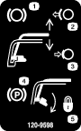
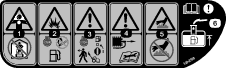
Safety and Instructional Decals
 |
Safety decals and instructions are easily visible to the operator and are located near any area of potential danger. Replace any decal that is damaged or missing. |


Setup
Note: Determine the left and right sides of the machine from the normal operating position.
Preparing the Traction Unit
Optional
If you are installing cutting unit 04251, 02452, 04253, or 04254 on this traction unit, complete the following steps:
Installing the Cutting Unit to the Traction Unit
Parts needed for this procedure:
| Bolt, 3/8 x 3/4 inch | 2 |
-
Place the machine on its drums on a level surface.
-
Lower the kick stand and push in the locking pin to lock the kick stand in the service position (Figure 5). Allow the machine to rest on the locking pin.
-
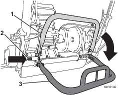
Push the cutting unit under the traction unit and to the left to engage the transmission coupling (Figure 6).
-
Maneuver the traction unit frame (Figure 7) forward until it engages the cutting unit pivot arms.
-
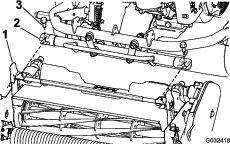
Secure the traction unit frame to the cutting unit pivot arms with 2 bolts (3/8 x 3/4 inch) (Figure 7).
Note: To remove the cutting unit, just loosen the 2 bolts (3/8 x 3/4 inch) approximately 1-1/2 turns and rotate the pivot arms out.
-
Push down on the kick stand to release the spring-loaded locking pin and allow the kick stand to rotate up to the storage position.
Installing the Handle Retainers
Parts needed for this procedure:
| Handle retainer | 2 |
| Hairpin cotter | 2 |
-
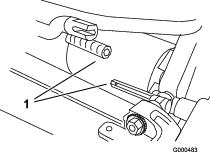
While supporting the handle, remove the cable ties securing the handle clamps to the side plates (Figure 8).
-
Pivot the handle to the desired operating position, insert a handle retainer over the handle clamp and into the matching holes in the side plate (Figure 8).
-
Secure the clamp in position with a hairpin cotter (Figure 8).
-
Repeat the procedure on the opposite side of the handle.
-
Adjust the handle height to the desired position; refer to Adjusting the Handle Height.
Note: The machine is shipped with the handle adjusted to the lowest position. The machine is traditionally operated with the handle telescoped out to its maximum height.
Installing the Transport Wheels
Parts needed for this procedure:
| Transport wheels (Optional Transport Wheel Kit, Model 04123) | 2 |
-
Push the kickstand down with your foot in the center of the kickstand and pull up on the lower center machine handle until the kickstand has rotated forward, over center (Figure 9).
-
Press the wheel locking clip toward the center of wheel and slide the wheel onto the hex shaft (Figure 10).
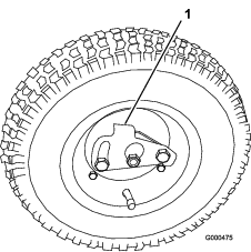
-
Rotate the wheel back and forth until it slides completely onto the axle and the locking clip is secured in the groove on the axle shaft.
-
Repeat the procedure on the opposite side of the machine.
-
Inflate the tires to 83 to 103 kPa (12 to 15 psi).
-
Carefully lower the machine off the kick stand by pushing forward slowly or by lifting the lower center handle support, allowing the kickstand to spring back to its normal position.
Checking the Engine-Oil Level
Check the engine-oil level, refer to Checking the Engine-Oil Level.
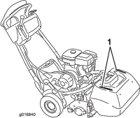
Installing the Grass Basket
Parts needed for this procedure:
| Grass basket | 1 |
-
Grasp the basket by the handle (Figure 11).
-
Guide the basket lip between the cutting unit side plates and over the front roller (Figure 11).
-
Install the basket hooks over the frame loop (Figure 11).
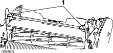
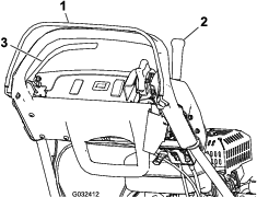
Important: If you ever drop the basket, examine the pitch arm contact points near the lower lip of the basket for damage (Figure 12). Straighten them before using the basket. Using the basket with bent pitch arm contact points may cause contact between the basket and reel causing undesired noise and/or damage to the basket and reel.
Product Overview
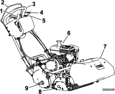
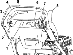
Throttle Control
Traction and Reel-Drive Engagement Lever
The traction and reel-drive engagement lever (Figure 16) is located on the front right side of the control panel. For transport operation, the lever has 2 positions: NEUTRAL and FORWARD. Pushing the lever forward engages the traction drive.
Note: To move the lever you must first engage the operator-presence control.
For reel operation, the lever has 2 positions: ENGAGE and DISENGAGE. Move the top of the lever to the left then forward to engage the reel and begin mowing. Push the lever to the right to disengage the reel and continue forward motion or pull back on it to disengage both the reel and the traction drive.
Note: If you release the operator-presence control, the lever returns to neutral and the machine stops.
Service Brake
The service brake (Figure 17) is located on the left front side of the handle. Pulling the lever back will apply the service brake. You must release the brake before you engage the traction drive.
Parking-Brake Latch
The parking-brake latch (Figure 17) is used with the service brake. With the service brake engaged, rotate the parking-brake latch toward the brake handle and release the service brake onto the latch to hold the service brake in place. Pull the brake lever to release it.
On/Off Switch
The on/off switch (Figure 14) is located on top of the control panel. Move the switch to the ON position to start the engine and OFF to shut off the engine.
Operator-Presence Control (OPC)
The operator-presence control (Figure 14) must be engaged before engaging the traction lever. Releasing the OPC during operation returns the machine to neutral but does not shut off the engine.
Choke Lever
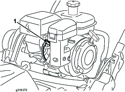
The choke lever (Figure 18) is located on the engine. The lever has 2 positions: RUN and CHOKE. Move the choke lever to the half-open position when starting a cold engine. After the engine starts, move the lever to the RUN position.
Fuel-Shutoff Valve
The fuel-shutoff valve (Figure 19) is located on the engine. The valve has 2 positions: CLOSED and OPEN. Move the lever to the CLOSED position when storing or transporting machine. Open the valve before starting the engine. The fuel cup is located below the shutoff valve.
Recoil-Starter Handle
Pull the recoil-starter handle (Figure 20) to start the engine.
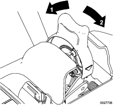
Kickstand
The kickstand (Figure 22) is mounted to the rear of the machine and is used to raise the rear of the machine for installing or removing the transport wheels and for preventing the machine for falling onto the handle when you remove the reel.
-
To use the kickstand to install the transport wheels, lower it to the ground and step down on the kickstand loop while pulling up and back on the lower center machine handle (Figure 21).
Caution
The machine is heavy and can cause back strain if lifted improperly.
Put foot pressure down only on the kickstand loop and only use the lower center machine handle to raise the unit. Attempting to raise the unit onto the kickstand any other way can cause injury.
-
To prevent the unit from tipping backward when removing the reel, lower the kickstand and push in the locking pin to lock it in the SERVICE position (Figure 23).
| Width | 82.5 cm (32-1/2 inches) |
| Height | 104.8 cm (41–1/4 inches) |
| Length with basket | 152.4 cm (60 inches) |
| Net Weight (with 11 blade cutting unit and grass basket installed) | 117 kg (258 lb) |
| Width of cut | 46 cm (18 inches) |
| Height of cut | 1.5 to 7.5 mm (1/16 to 19/64 inches) with Micro-Cut bedknife |
| Clip frequency | Adjustable (refer to Cutting Unit Operator’s Manual) |
| Width | 90.1 cm (35-1/2 inches) |
| Height | 104.8 cm (41–1/4 inches) |
| Length with basket | 152.4 cm (60 inches) |
| Net Weight (with 11 blade cutting unit and grass basket installed) | 117.9 kg (260 lb) |
| Width of cut | 53.3 cm (21 inches) |
| Height of cut | 1.5 to 7.5 mm (1/16 to 19/64 inches) with Micro-Cut bedknife |
| Clip frequency | Adjustable (refer to Cutting Unit Operator’s Manual) |
Attachments/Accessories
A selection of Toro approved attachments and accessories is available for use with the machine to enhance and expand its capabilities. Contact your Authorized Service Dealer or Distributor or go to www.Toro.com for a list of all approved attachments and accessories.
To best protect your investment and maintain optimal performance of your Toro equipment, count on Toro genuine parts. When it comes to reliability, Toro delivers replacement parts designed to the exact engineering specification of our equipment. For peace of mind, insist on Toro genuine parts.
Operation
Note: Determine the left and right sides of the machine from the normal operating position.
Think Safety First
Carefully read all safety instructions and symbols in the safety section. Knowing this information could help you or bystanders avoid injury.
Caution
This machine produces sound levels that can cause hearing loss through extended periods of exposure.
Wear hearing protection when operating this machine.

Checking the Engine-Oil Level
Check the engine-oil level before each use or every 8 operating hours, refer to Checking the Engine-Oil Level.
Filling the Fuel Tank
The fuel tank capacity is 3.0L (0.79 gallons).
-
For best results, use only clean, fresh (less than 30 days old), unleaded gasoline with an octane rating of 87 or higher ((R+M)/2 rating method).
-
Ethanol: Gasoline with up to 10% ethanol (gasohol) or 15% MTBE (methyl tertiary butyl ether) by volume is acceptable. Ethanol and MTBE are not the same. Gasoline with 15% ethanol (E15) by volume is not approved for use. Never use gasoline that contains more than 10% ethanol by volume, such as E15 (contains 15% ethanol), E20 (contains 20% ethanol), or E85 (contains up to 85% ethanol). Using unapproved gasoline may cause performance problems and/or engine damage which may not be covered under warranty.
-
Do not use gasoline containing methanol.
-
Do not store fuel either in the fuel tank or fuel containers over the winter unless a fuel stabilizer is used.
-
Do not add oil to gasoline.
Danger
In certain conditions, gasoline is extremely flammable and highly explosive. A fire or explosion from gasoline can burn you and others and can damage property.
-
Fill the fuel tank outdoors, in an open area, when the engine is cold. Wipe up any gasoline that spills.
-
Never fill the fuel tank inside an enclosed trailer.
-
Do not fill the fuel tank completely full. Add gasoline to the fuel tank until the level is 6 to 13 mm (1/4 to 1/2 inch) below the bottom of the filler neck. This empty space in the tank allows gasoline to expand.
-
Never smoke when handling gasoline, and stay away from an open flame or where gasoline fumes may be ignited by a spark.
-
Store gasoline in an approved container and keep it out of the reach of children. Never buy more than a 30-day supply of gasoline.
-
Do not operate without entire exhaust system in place and in proper working condition.
Danger
In certain conditions during fueling, static electricity can be released causing a spark which can ignite the gasoline vapors. A fire or explosion from gasoline can burn you and others and can damage property.
-
Always place gasoline containers on the ground away from your vehicle before filling.
-
Do not fill gasoline containers inside a vehicle or on a truck or trailer bed because interior carpets or plastic truck bed liners may insulate the container and slow the loss of any static charge.
-
When practical, remove gas-powered equipment from the truck or trailer and refuel the equipment with its wheels on the ground.
-
If this is not possible, then refuel such equipment on a truck or trailer from a portable container, rather than from a gasoline dispenser nozzle.
-
If a gasoline dispenser nozzle must be used, keep the nozzle in contact with the rim of the fuel tank or container opening at all times until fueling is complete.
Warning
Gasoline is harmful or fatal if swallowed. Long-term exposure to vapors can cause serious injury and illness.
-
Avoid prolonged breathing of vapors.
-
Keep face away from nozzle and gas tank or conditioner bottle opening.
-
Avoid contact with skin; wash off spillage with soap and water.
-
Clean around the fuel-tank cap and remove the cap from the tank (Figure 25). Using unleaded gasoline, fill the fuel tank no higher than to the bottom of the filter screen. Do not overfill.
-
Install the fuel-tank cap and wipe up any spilled gasoline.
Adjusting the Handle Height
Note: The machine is shipped with the handle adjusted to the lowest position. The machine is traditionally operated with the handle telescoped out to its maximum height.
-
Loosen the 3 carriage bolts and nuts securing each side of the handle in the handle clamps (Figure 26).
-
Pull up on the handle slowly and evenly on each side until it is in the desired operating position.
-
Tighten the carriage bolts and nuts to lock the adjustment.
Adjusting the Handle Angle
Adjusting the Throttle Control
-
Remove the console cover.
-
Loosen the 2 fasteners securing the throttle control (Figure 28).
-
Adjust the throttle control to the desired position.
-
Tighten the throttle-control fasteners.
-
Install the previously removed console cover.
Starting and Shutting Off the Engine
Note: For illustrations and descriptions of the controls referenced in this section, refer to Controls.
Starting the Engine
Note: Ensure that the spark-plug wire is installed on the spark plug.
-
Ensure that the traction and reel-drive levers are in the Disengaged position.
Note: The engine will not start if the traction lever is in the engaged position.
-
Move the on/off switch to the ON position.
-
Move the throttle control to the FAST position.
-
Open the fuel-shutoff valve on the engine.
-
Move the choke lever to the half-open position when starting a cold engine. The choke may not be required when starting a warm engine.
-
Pull the recoil starter handle out until positive engagement results, then pull it vigorously to start the engine. Open the choke as the engine warms up.
Important: Do not pull the recoil rope to its limit or let go of the starter handle when the rope is pulled out because the rope may break or the recoil assembly may be damaged.
Shutting Off the Engine
-
Move the traction and reel drive controls to the DISENGAGED position, the throttle control to SLOW, and the on/off switch to OFF.
-
Pull the molded spark-plug wire off of the spark plug to prevent the possibility of accidental starting before storing the machine.
-
Close the fuel-shutoff valve before storing or transporting the machine in a vehicle.
Transporting the Machine
Note: Do not run the engine while transporting it in a transport trailer because damage can occur to the machine.
If the optional transport wheels are not going to be installed, proceed to step 4.
-
Push the kick stand down with your foot and pull up on the handle support until the kickstand has rotated forward, over center.
-
Install the transport wheels.
-
To release the kickstand, pull up on the handle and lower the rear of the machine onto the transport wheels.
-
Ensure that the traction and reel drive controls are in the DISENGAGED position and start the engine.
-
Set the throttle control to SLOW, tip the front of the machine up, gradually engage the traction drive, and slowly increase the engine speed.
-
Adjust the throttle to operate the machine at the desired ground speed and transport the machine to the desired destination.
Preparing to Mow
-
Return the traction control lever to the DISENGAGED position, the throttle to the SLOW position, and shut off the engine.
-
Push the kick stand down with your foot and pull up on the handle support until the kickstand has rotated forward, over center.
-
Remove the transport wheels.
-
Carefully lower the machine off the kickstand.
Ensure that the machine is carefully adjusted and that it is set evenly on both sides of the reel. Improper machine adjustment is magnified in the appearance of the clipped turf. Remove all foreign objects from the turf prior to mowing. Make sure that everyone, especially children and pets, are clear of the work area.
Mowing Tips
Important: Grass clippings act as a lubricant when mowing. Excessive operation of the cutting unit with the absence of grass clippings can damage the cutting unit.
-
The greens should be mowed in a straight back and forth direction across the green.
-
Avoid circular mowing or turning the machine on the greens areas to prevent scuffing.
-
Turning the machine should be done off the green by raising the cutting reel (pushing the handle down) and turning on the traction drum.
-
Mowing should be done at a normal walking pace. Fast speeds saves very little time and results in an inferior mowing job.
-
To assist in maintaining a straight line across the green and to keep the machine an equal distance from the edge of the previous cut, use the alignment stripes on the basket (Figure 29).
Operating the Machine in Low Light Conditions
When operating the machine in low light conditions, use the optional LED Light Kit, available from your Authorized Toro Distributor.
Important: Do not use other light systems with this machine as they will not operate properly with the engine AC output.
Operating the Controls while Mowing
-
Start the engine, set the throttle to a reduced speed, push down on the handle to raise the cutting unit, press the operator-presence control, move the traction lever to the ENGAGED position and transport the machine onto the collar of the green (Figure 30).
-
Move the traction lever to the DISENGAGED position and engage the reel-drive lever (Figure 30).
-
Move the traction lever to the ENGAGED position, increase the throttle speed until the machine is traveling at the desired ground speed, drive the machine out onto the green area, lower the front of the machine down, and commence operation (Figure 30).
Operating the Controls after Mowing
-
Drive off the green, move the reel drive and traction control levers to the DISENGAGED position, and shut off the engine.
-
Empty the grass basket of clippings, install the grass basket on the machine, and commence the transport operation.
Checking the Operation of the Interlock Switches
Caution
If the safety interlock switches are disconnected or damaged, the machine could operate unexpectedly, causing personal injury.
-
Do not tamper with the interlock switches.
-
Check the operation of the interlock switches daily and replace any damaged switches before operating the machine.
Checking the Operator-Presence Control (OPC) Interlock Switch
-
Push the kick stand down with your foot and pull up on the handle support until the kickstand has rotated forward, over center.
-
Start the engine.
-
With the OPC released, attempt to engage the traction lever (Figure 31). The traction lever should not engage. If the traction lever engages, the interlock system needs service. Correct the problem before operating; refer to Servicing the Traction Interlock Switch .
-
With the OPC pressed and the traction lever engaged, release the OPC (Figure 31). The traction lever should disengage. If the traction lever does not disengage, the interlock system needs service. Correct the problem before operating; refer to Servicing the Traction Interlock Switch .
-
With the OPC pressed and the shift lever moved to the left, engage the traction and reel drive, release the OPC (Figure 31). The traction lever should disengage. If the traction lever does not disengage, the interlock system needs service. Correct the problem before operating.; refer to Servicing the Traction Interlock Switch or Adjusting the Reel Control.
-
With the OPC pressed and the shift lever moved to the left to engage the traction and reel drive, move the shift lever to the right to disengage the reel drive (Figure 31). The reel drive should disengage. If the reel drive does not disengage, the interlock system needs service. Correct the problem before operating.; refer to Adjusting the Reel Control.
-
Carefully lower the machine off the kickstand.
Checking the Traction Interlock Switch
-
Push the kickstand down with your foot and pull up on the handle support until the kickstand has rotated forward, over center.
-
With the OPC pressed, the traction lever engaged, and the engine controls in the starting position (Figure 31). Attempt to start the engine. The engine should not start. If the engine starts, the interlock switch needs service. Correct the problem before operating. Refer to Servicing the Traction Interlock Switch .
-
Carefully lower the machine off the kickstand.
Checking the Brake-Interlock Switch
-
Push the kickstand down with your foot and pull up on the handle support until the kickstand has rotated forward, over center.
-
With the traction lever disengaged, the service brake engaged, and the engine controls in the starting position (Figure 31), attempt to start the engine. The engine should start. If the engine does not start, the interlock switch needs service. Correct the problem before operating the machine; refer to Servicing the Brake-Interlock Switch.
-
With the engine running, engage the service brake (not the parking brake), press the OPC, and engage the traction lever (Figure 31). The engine should labor to overcome the brake but should not shut off. If the engine shuts off immediately, the interlock switch needs service. Correct the problem before operating the machine; refer to Servicing the Brake-Interlock Switch.
-
With the engine running, engage the parking-brake latch, press the OPC, and engage the traction lever (Figure 31). The engine should shut off. If the engine does not shut off, the interlock switch needs service. Correct the problem before operating; refer to Servicing the Brake-Interlock Switch.
-
Carefully lower the machine off the kickstand.
Releasing the Transmission
If the machine becomes disabled, you can disengage the drum from the transmission to allow the machine to be maneuvered.
-
On the right rear corner of the machine, locate the traction engage/disengage lever next to the drive housing drum (Figure 32).
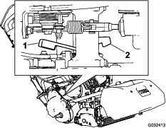
-
Rotate the lever rearward to disengage the transmission from the drum.
Caution
Not carefully rotating the lever may cause the spring-loaded lever to strike your hand.
Carefully rotate the lever.
-
Move the machine as needed.
Important: If possible, do not tow the machine. If it is absolutely necessary, do not tow at any speed greater than 4.8 kph (3 mph); always disengage the transmission from the drum. Failing to do so will likely damage the machine.
-
When finished, rotate the lever forward to engage the transmission to the drum.
Note: The brake is still operational with the transmission disengaged from the drum.
Setting the Machine to Match Turf Conditions
Use the following table to set the machine to match turf conditions.
| Bedbars: Standard and Optional (Flex/eFlex 2120 Machines) | |||
| Part Number | Description | Aggressiveness | Comments |
| 106-2468-01 | Non-Aggressive | Less | Red, Standard |
| 99-3794-03 | Aggressive | More | Black |
| Bedbars: Standard and Optional (Flex/eFlex 1820 Mowers) | |||
| 110-2282-01 | Non-Aggressive | Less | Red, Standard |
| 110-2281-03 | Aggressive | More | Black |
| Bedknives: Standard and Optional (Flex/eFlex 2120 Machines) | |||
| Part Number | Description | Height-of-cut Range | Comments |
| 115-1880 | Microcut-EdgeMax | 1.6 to 3.2 mm (0.062 to 0.125 inch) | Standard |
| 93-4262 | Microcut | 1.6 to 3.2 mm (0.062 to 0.125 inch) | |
| 108-4303 | Extended Microcut | 1.6 to 3.2 mm (0.062 to 0.125 inch) | Less aggressive |
| 115-1881 | Tournament- EdgeMax | 3.2 to 6.4 mm (0.125 to 0.25 inch) | |
| 93-4263 | Tournament | 3.2 to 6.4 mm (0.125 to 0.25 inch) | |
| 108-4302 | Extended Tournament | 3.2 to 6.4 mm (0.125 to 0.25 inch) | Less aggressive |
| 93-4264 | Low Cut | 6.4 mm (0.25 inch) and up | |
| Bedknives: Standard and Optional (Flex/eFlex 1820 Machines) | |||
| 117-1530 | Microcut-EdgeMax | 1.6 to 3.2 mm (0.062 to 0.125 inch) | Standard |
| 98-7261 | Microcut | 1.6 to 3.2 mm (0.062 to 0.125 inch) | |
| 110-2300 | Extended Microcut | 1.6 to 3.2 mm (0.062 to 0.125 inch) | Less aggressive |
| 98-7260 | Tournament | 3.2 to 6.4 mm (0.125 to 0.25 inch) | |
| 117-1532 | Tournament- EdgeMax | 3.2 to 6.4 mm (0.125 to 0.25 inch) | |
| 110-2301 | Low Cut | 6.4 mm (0.25 inch) and up | |
| Rollers (Flex/eFlex 2120 Machines) | |||
| Part Number | Description | Diameter/Material | Comments |
| 04255 | Narrow Wiehle | 6.4 cm (2.5 inches)/Aluminum | Narrow spaced grooves |
| 04256 | Wide Wiehle | 6.4 cm (2.5 inches)/Aluminum | More penetration, wide spaced grooves |
| 04257 | Full Roller | 6.4 cm (2.5 inches)/Steel | Least penetration |
| 04258 | Narrow Wiehle—Long | 6.4 cm (2.5 inches)/Aluminum | More edge support; 4.3 cm (1.7 inches) longer |
| 04267 | Paspalum | 6.4 cm (2.5 inches)/Aluminum | Less penetration, softened narrow spaced grooves |
| 115-7356 | Rear Roller | 5.1 cm (2.0 inches)/Aluminum | Standard rear |
| 120-9595 | Rear Roller | 5.1 cm (2.0 inches)/Steel | Steel rear |
| Rollers (Flex/eFlex 1820 Machines) | |||
| 120-9607 | Narrow Wiehle | 6.4 cm (2.5 inches)/Aluminum | Narrow spaced grooves |
| 120-9609 | Wide Wiehle | 6.4 cm (2.5 inches)/Aluminum | More penetration, wide spaced grooves |
| 120-9611 | Full Roller | 6.4 cm (2.5 inches)/Steel | Least penetration |
| 121-4681 | Narrow Wiehle—Long | 6.4 cm (2.5 inches)/Aluminum | More edge support; 4.3 cm (1.7 inches) longer |
| 120-9605 | Rear Roller | 5.1 cm (2.0 inches)/Aluminum | Standard rear |
Maintenance
Note: Determine the left and right sides of the machine from the normal operating position.
Important: When using the machine in conjunction with the Trans Pro 80, always use the stops on the trailer when servicing the machine. Overtipping can result in fuel spillage. The stop on the Rail Ramp Kit requires a broom handle or similar item to be inserted through the holes behind the wheels.
Recommended Maintenance Schedule(s)
| Maintenance Service Interval | Maintenance Procedure |
|---|---|
| After the first 20 hours |
|
| Before each use or daily |
|
| Every 50 hours |
|
| Every 100 hours |
|
| Every 500 hours |
|
| Every 1,000 hours |
|
| Before storage |
|
Important: Refer to your engine owner's manual for additional maintenance procedures.
Engine Maintenance
Servicing the Engine Oil
Fill the crankcase with approximately 0.6 L (20 fl oz) of the proper viscosity oil before starting. Use a high-quality oil having the American Petroleum Institute (API) service classification SE or higher. Select the proper oil viscosity (weight) based on the ambient temperature. Figure 33 illustrates the temperature/viscosity recommendations.
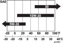
Note: Using multi-grade oils (5W-20, 10W-30 and 10W-40) will increase oil consumption. Check the oil level more frequently when using them.
Checking the Engine-Oil Level
| Maintenance Service Interval | Maintenance Procedure |
|---|---|
| Before each use or daily |
|
Note: The best time to check the engine oil is when the engine is cool, before it has been started for the day. If it has already been run, allow the oil to drain back down to the sump for at least 10 minutes before checking. If the oil level is at or below the L mark on the dipstick, add oil to bring the oil level to the H mark. Do not overfill. If the oil level is between the H and L marks, do not add oil.
-
Remove the transport wheels (if installed).
-
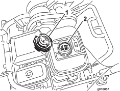
Position the machine so that the engine is level and clean around the oil-level gauge (Figure 34).
-
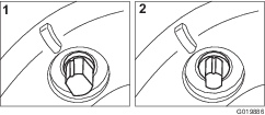
Remove the oil-level gauge by rotating it counterclockwise (Figure 34).
-
Wipe the oil-level gauge clean and insert it into the filler port. Do not screw the gauge into the port. Then remove it and check the level of the oil. If the level is low, add only enough oil to raise the level until it is between the H and L marks on the gauge (Figure 35). Check the level of the oil. Do not overfill.

-
Install the oil-level gauge and wipe up any spilled oil.
Changing the Engine Oil
| Maintenance Service Interval | Maintenance Procedure |
|---|---|
| After the first 20 hours |
|
| Every 50 hours |
|
-
Start and run the engine for a few minutes to warm the engine oil.
-
At the rear of the machine, place a drain pan under the drain plug (Figure 34). Loosen the drain plug.
-
Push down on the handle to tip the machine and engine backward, allowing all the oil to run into the drain pan.
-
Install the drain plug and refill the crankcase with the specified oil.
-
Wipe up any spilled oil.
-
Dispose of the used oil properly. Recycle according to local codes.
Servicing the Air Cleaner
| Maintenance Service Interval | Maintenance Procedure |
|---|---|
| Every 50 hours |
|
| Every 100 hours |
|
-
Disconnect the wire from the spark plug.
-
Remove the wing nut securing the air-cleaner cover to the air cleaner and remove the cover. Clean the cover thoroughly (Figure 36 and Figure 37).
-
If the foam element is dirty, remove it from the paper element (Figure 37). Clean it thoroughly.
-
Wash the foam element in a solution of liquid soap and warm water. Squeeze it to remove the dirt, but do not twist it because the foam may tear.
-
Dry by wrapping in a clean rag. Squeeze the rag and foam element to dry, but do not twist because the foam may tear.
-
Saturate the element with clean engine oil. Squeeze the element to remove the excess oil and to distribute the oil thoroughly.
Note: An element damp with oil is desirable.
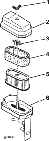
-
-
When servicing the foam element, check the condition of the paper element. Replace as required.
Note: Do not use compressed air to clean the paper element.
-
Install the foam element, paper element, and air-cleaner cover.
Important: Do not operate the engine without the air-cleaner element because extreme engine wear and damage will result.
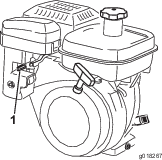
Servicing the Spark Plug
| Maintenance Service Interval | Maintenance Procedure |
|---|---|
| Every 100 hours |
|
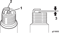
Use an NGK BR6HS spark plug or equivalent. The correct air gap is 0.6 to 0.7 mm (0.024 to 0.028 inch).
-
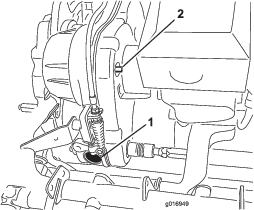
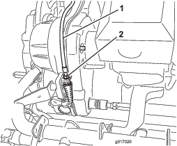
Pull the molded wire off the spark plug (Figure 38).
-
Clean around the spark plug and remove the plug from the cylinder head.
Important: Replace a cracked, fouled, or dirty spark plug. Do not sand blast, scrape, or clean the electrodes because engine damage could result from grit entering the cylinder.
-
Set the air gap at 0.6 to 0.7 mm (0.024 to 0.028 inch) as shown in Figure 39. Install the correctly gapped spark plug and tighten it firmly to 23 N∙m (17 ft-lb).
Fuel System Maintenance
Cleaning the Fuel Cup and Fuel-Tank Screen
| Maintenance Service Interval | Maintenance Procedure |
|---|---|
| After the first 20 hours |
|
| Every 100 hours |
|
-
Close the fuel shut off valve and unscrew the fuel cup from the filter body (Figure 40).
Note: A 17 mm, 12 point socket fits over the body of the fuel cup and aids in the removal.
-
Clean the fuel cup in clean fuel and install it.
-
Unscrew and remove the fuel-tank cap from the fuel tank (Figure 41).
-
Remove the fuel-tank screen from inside the fuel tank.
-
Clean the screen in clean fuel and install it in the tank.
-
Install the fuel-tank cap to the fuel tank.
Replacing the Fuel Line
| Maintenance Service Interval | Maintenance Procedure |
|---|---|
| Every 1,000 hours |
|
If fuel leaks from the line, replace it immediately.
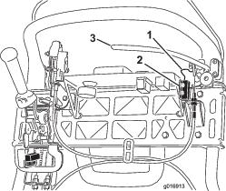
Electrical System Maintenance
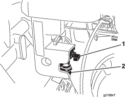
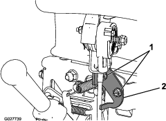
Servicing the Traction Interlock Switch
Use the following procedure if the switch needs adjustment or replacement.
-
Make sure that the engine is off.
-
Remove the control panel.
-
Engage the traction lever.
-
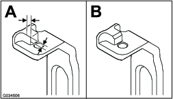
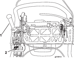
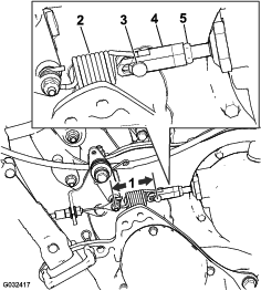
Loosen the interlock switch mounting fasteners (Figure 42).
-
Place a 1.6 mm (0.062 inch) thick shim between the traction lever and the interlock switch (Figure 42).
-
Tighten the interlock switch mounting fasteners.
-
Engage the traction lever and check the gap. The normal operating range is between 0.76 to 3.05 mm (0.03 to 0.12 inch). With the traction lever engaged, verify that the switch loses continuity. Replace the switch if required.
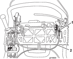
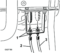
Servicing the Brake-Interlock Switch
-
Make sure that the engine is off.
-
Remove the control panel.
-
Engage the service-brake lever and engage the parking-brake latch.
-
Loosen the interlock switch mounting fasteners (Figure 43).
-
Place a 1.6 mm (0.062 inch) thick shim between the parking-brake latch and the interlock switch (Figure 43 ).
-
Tighten interlock switch mounting fasteners. Check the gap. The latch must not contact the switch.
-
Engage the brake lever and rotate the latch. Verify that the switch loses continuity. Replace the switch if required.
Brake Maintenance
Adjusting the Service/Parking Brake
If the service/parking brake slips when operated, adjust the cable as follows:
-
Move the service/parking brake lever to the OFF position.
-
Remove the control panel.
-
To increase the cable tension, loosen the upper cable jam nut and tighten the lower cable jam nut (Figure 44) until a force of 156 N (35 lb) applied to the brake lever handle is required to release the parking-brake latch. Do not over adjust it or the brake band may drag.
Belt Maintenance
Inspecting the Reel-Drive Belt
| Maintenance Service Interval | Maintenance Procedure |
|---|---|
| Every 1,000 hours |
|
-
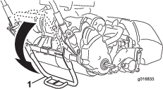
Loosen the flange bolt securing the belt cover and remove the belt cover to expose the belt (Figure 45).
-
To adjust the belt tension:
-
Loosen the bearing housing mounting nut (Figure 46).
-
Using a 16 mm (5/8 inch) wrench, rotate the bearing housing to make sure that it operates freely.
-
Clean any debris from inside the belt compartment and from around the compression spring (Figure 46).
-
Make sure that the compression spring is applying the proper tension on the belt.
-
Tighten the bearing housing mounting nut.
-
Install the belt cover.
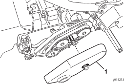
-
Visually Inspecting the Reel Clutch
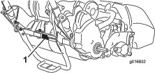
Remove the rubber plug (Figure 47) from the hole in the front of the transmission to visually inspect the reel clutch when making adjustments.
Important: Replace the plug when finished to prevent water and debris from contaminating the clutch.
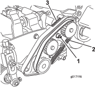
Engaging/Disengaging the Transmission-Belt Tensioner
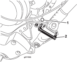
The transmission belt is tensioned by a spring loaded idler pulley. If you must engage or disengage the belt tension, use a 3/8 inch wrench to rotate the engage/disengage shaft (Figure 47) to the desired position. Rotating the shaft 1/4 turn clockwise disengages the idler from the belt (Figure 48).
Note: The belt tension must be disengaged prior to removing the transmission cover.
Controls System Maintenance
Adjusting the Traction Control
| Maintenance Service Interval | Maintenance Procedure |
|---|---|
| Every 500 hours |
|
If the traction control does not engage or slips during operation, the traction control may need adjusting.
-
Move the traction control to the ENGAGED position.
-
Measure the distance from the pin on either end of the traction-control spring (Figure 49); if it is not within 7.3 to 7.6 cm (2-7/8 to 3 inches), adjust the clutch according to the steps below.
-
Disengage the traction-control lever.
-
Loosen the jam nut on the turnbuckle and remove the clevis pin, disconnecting the spring from the turnbuckle (Figure 49).
-
Turn the turnbuckle in or out to adjust the length as needed.
-
Install the turnbuckle to the spring using the clevis pin.
-
Move the traction control to the ENGAGED position.
-
Measure the distance from the pin on either end of the traction-control spring (Figure 49); repeat steps 1 through 6 until it is within 7.3 to 7.6 cm (2-7/8 to 3 inches).
-
Adjusting the Reel Control
If the reel control does not properly engage, an adjustment is required.
-
Ensure that the reel control is disengaged.
-
At the transmission bulkhead, adjust the reel-control cable (Figure 50) to attain a spring length of 70.6 to 72.4 mm (2.78 to 2.85 inches).
-
At the control handle bulkhead, loosen the reel-control cable until there is slack in the cable (Figure 51).
-
At the control handle bulkhead, tighten the reel-control cable enough to remove the slack from the cable without extending the spring.
-
Check the operation as follows:
-
Verify that the reel clutch teeth disengage when the clutch is released and the reel clutch teeth do not bottom out when engaged.
Note: Remove the rubber plug (Figure 47) from the hole in the front of the transmission to view reel clutch.
-
The reel stopping time must be less than 7 seconds with the reel to bedknife backed off.
-
Refer to the Service Manual or contact your authorized Toro distributor for further assistance.
-
Storage
-
Remove any grass clippings, dirt, and grime from the external parts of the entire machine, especially the engine. Clean the dirt and chaff from the outside of the engine cylinder-head fins and the blower housing.
Important: You can wash the machine with mild detergent and water. Do not pressure wash the machine. Avoid excessive use of water, especially near the shift lever plate, and the engine.
-
For long-term storage (more than 30 days) add stabilizer/conditioner additive to the fuel in the tank.
-
Run the engine to distribute conditioned fuel through the fuel system (5 minutes).
-
Either shut off the engine, allow it to cool, and drain the fuel tank, or operate the engine until it shuts off.
-
Start the engine and run it until it shuts off. Repeat, on CHOKE, until the engine no longer starts.
-
Dispose of fuel properly. Recycle according to local codes.
Note: Do not store stabilizer/conditioned fuel over 90 days.
-
-
Check and tighten all bolts, nuts, and screws. Repair or replace any part that is worn or damaged.
-
Paint all scratched or bare metal surfaces. Paint is available from your authorized Toro distributor.
-
Store the machine in a clean, dry garage or storage area. Cover the machine to protect it and keep it clean.