CALIFORNIA
Proposition 65 Warning
Park the machine on a level surface.
Engage the parking brake.
Shut off the engine and remove the key.

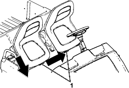
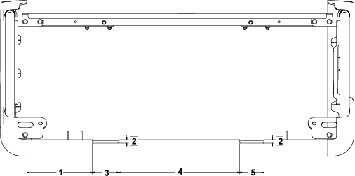
Remove the 3 flange bolts (5/16 x 3/4 inch) and 3 flange nuts (5/16 inch) from the right handhold, and remove the right handhold (Figure 2).
Note: Retain the handhold and fasteners.
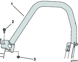
Remove front flange bolt (5/16 x 3/4 inch) and flange nut (5/16 inch) from the left handhold, but do not remove the left handhold.
Remove the 3 screws (#10 x 1/2 inch), 2 bolts with washer assemblies (1/4 x 1/2 inch), and 2 torx-head screws securing the existing seat support (Figure 3).
Note: Retain the fasteners.
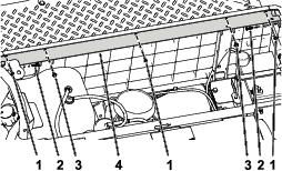
Remove the existing seat support (Figure 3).
Note: Discard the seat support.
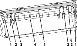
Remove the 4 torx-head screws from the seat-retainer brackets, and the 2 flange-head bolts and 2 washers closest to each bracket (Figure 4).
Note: Retain the fasteners.
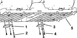
Remove the 2 seat-retainer brackets from the seat-base assembly (Figure 4).
Note: Discard the seat-retainer brackets.
Using a utility knife improperly could cause personal injury.
When cutting, keep your body away from the path of the blade.
Use a sharp blade.
Measuring left to right, measure 22.1 cm (8-11/16 inches) from the edge of the seat-base panel, and mark this spot (Figure 5).
Measure 11.7 mm (7/16 inch) from the top edge of the seat-base panel (toward you), and mark this spot (Figure 5).
Measure 8.9 cm (3-1/2 inches) from the marked spot, and mark this spot (Figure 5).
Measure 11.7 mm (7/16 inch) from the top edge of the seat-base panel (toward you), and mark this spot (Figure 5).
Cut out the opening for the first seat-hinge bracket.
Measure 40.8 cm (16-1/16 inches) from the opening, and marking this spot (Figure 5).
Measure 11.7 mm (7/16 inch) from the top edge of the seat-base panel (toward you), and mark this spot (Figure 5).
Measure 8.25 cm (3-1/4 inches) from the marked spot, and mark this spot (Figure 5).
Measure 11.7 mm (7/16 inch) from the top edge of the seat-base panel (toward you), and mark this spot (Figure 5).
Cut out the opening for the second seat-hinge bracket.
Parts needed for this procedure:
| Seat support | 1 |
Install the new seat support using the previously removed 3 screws (#10 x 1/2 inch), 2 bolt with washer assemblies (1/4 x 1/2 inch), and 2 torx-head screws (Figure 6).
Install the previously removed right handhold using the previously removed 3 flange bolts (5/16 x 3/4 inch) and 3 flange nuts (5/16 inch) as shown in Figure 7.
Torque the 3 flange nuts (5/16 inch) to 23 to 26 N∙m (200 to 230 in-lb).
Secure the front of the left handhold using the previously removed flange bolt (5/16 x 3/4 inch) and flange nut (5/16 inch).
Torque the flange nut (5/16 inch) to 23 to 26 N∙m (200 to 230 in-lb).
Parts needed for this procedure:
| Seat-hinge bracket | 2 |
| Screw (1/4 x 1 inch)—for bench seats only | 4 |
Important: If necessary, use the supplied 4 screws (1/4 x 1 inch) on a bench seat only.
Install the 2 seat-hinge brackets onto the seat-base assembly using the previously removed 4 torx-head screws, 2 flange-head bolts, and 2 washers (Figure 8).

Torque the flange-head bolts to 10 to 12 N∙m (90 to 110 in-lb).
Torque the torx-head screws to 203 to 249 N∙cm (18 to 22 in-lb).