Introduction

Read this information carefully to learn how to operate and maintain your product properly and to avoid injury and product damage. You are responsible for operating the product properly and safely.

You may contact Toro directly at www.Toro.com for product safety and operation training materials, accessory information, help finding a dealer, or to register your product.

Whenever you need service, genuine Toro parts, or additional information, contact an Authorized Service Dealer or Toro Customer Service and have the model and serial numbers of your product ready. Figure 1 identifies the location of the model and serial numbers on the product. Write the numbers in the space provided.

g016942

This manual identifies potential hazards and has safety messages identified by the safety-alert symbol (Figure 2), which signals a hazard that may cause serious injury or death if you do not follow the recommended precautions.

g000502

This manual uses 2 words to highlight information. Important calls attention to special mechanical information and Note emphasizes general information worthy of special attention.

Warning

CALIFORNIA

Proposition 65 Warning

Close section

Safety

Hazard control and accident prevention are dependent upon the awareness, concern, and proper training of the personnel involved in the operation, transport, maintenance, and storage of the machine. Improper use or maintenance of the machine can result in injury or death. To reduce the potential for injury or death, comply with the following safety instructions.

  • Read, understand, and follow all instructions in the traction unit and cutting unit operator’s manuals before operating the cutting unit.

  • Keep children out of the operating area. Never allow children to operate the machine.

  • Never operate the cutting units while ill, tired, or under the influence of drugs or alcohol.

  • Do not operate the machine without all guards and other safety protective devices in place and working on the machine.

  • Wear appropriate clothing, including eye protection, slip resistant, substantial footwear, and hearing protection. Tie back long hair and do not wear jewelry.

  • Remove all debris or other objects that the cutting-unit blades might pick up and throw. Keep all bystanders away from the working area.

  • If the cutting blades strike a solid object or the unit vibrates abnormally, stop and shut off the engine. Check the cutting unit for damaged parts. Repair any damage before starting the cutting unit.

  • Keep all nuts, bolts, and screws tight to be sure the equipment is in safe working condition.

  • Remove the key from ignition switch to prevent accidental starting of the engine when servicing, adjusting, or storing the machine.

  • If major repairs are ever needed or if assistance is desired, contact an authorized Toro distributor.

  • To ensure optimum performance and continued safety certification of the machine, use only genuine Toro replacement parts and accessories. Replacement parts and accessories made by other manufacturers could be dangerous, and such use could void the product warranty.

Safety and Instructional Decals

Graphic

Safety decals and instructions are easily visible to the operator and are located near any area of potential danger. Replace any decal that is damaged or missing.

decal104-7729
decal120-9570
decal131-1820
Close section
Close section

Setup

Installing the Front Roller

The cutting unit is shipped without a front roller. Install the roller using the loose parts supplied with the cutting unit and installation instructions included with the roller.

Close section

Using the Cutting-Unit Prop

Whenever you tip the cutting unit to expose the bedknife/reel, prop up the rear of the cutting unit to ensure that the nuts on the back end of the bedbar-adjusting screws are not resting on the work surface (Figure 3).

g016943
Close section

Adjusting the Bedknife to the Reel

Note: Use this procedure after grinding, backlapping, or disassembling the reel This is not a daily adjustment.

Note: For eFlex cutting units, the reel-to-bedknife contact has significant impact on energy consumption. Very light contact is recommended for optimum cutting performance and minimum battery consumption.

  1. Position the cutting unit on a flat, level work surface.

  2. Tip the cutting unit to expose the bedknife and reel.

    Note: Ensure that the nuts or back of the bedbar adjusting screws are not resting on the work surface (Figure 3).

  3. Rotate the reel so that 1 of the blades crosses the bedknife edge between the first and second bedknife screw heads located on the right side of the cutting unit.

  4. Make and identifying mark on the blade where it crosses the bedknife edge.

    Note: This will make later adjustments easier.

  5. Insert a 0.05 mm (0.002 inch) shim between the blade and the bedknife edge at the point marked in step 4.

  6. Turn the right bedbar adjusting screw (Figure 4) until you feel light pressure on the shim when sliding it side-to-side. Remove the shim.

    g014595
  7. For the left side of the cutting unit, slowly rotate the reel so that the closest blade crosses the bedknife edge between the first and second screw heads.

  8. Repeat steps 4 through 6 for the left side of the cutting unit and left bedbar adjusting screw.

  9. Repeat steps 5 and 6 until there is light pressure at the contact points on both the left and right sides of the cutting unit.

  10. To obtain light contact between the reel and bedknife, turn each bedbar adjusting screw clockwise 3 click.

    Note: Each click on the bedbar adjusting screw moves the bedknife 0.018 mm (0.0007 inch). Do not overtighten the adjusting screws.Turning the adjusting screw clockwise moves the bedknife edge closer to the reel. Turning the adjusting screw counterclockwise moves the bedknife edge away from the reel.

  11. Test the cutting performance by inserting a long strip of cutting performance paper between the reel and bedknife, perpendicular to the reel and bedknife (Figure 5). Slowly rotate the reel forward to cut the paper.

    g014411
Close section

Adjusting the Rear Roller

Depending on your desired height-of-cut range you need to adjust the rear roller brackets (Figure 6 or Figure 7) to the low or high position:

  • Position the spacer above the sideplate mounting flange (factory setting) when the height-of-cut settings range from 1.5 mm to 6 mm (1/16 inch to 1/4 inch) as shown in Figure 6.

    g014404
  • Position the spacer below the sideplate mounting flange when the height of cut settings range from 3 mm to 25 mm (1/8 inch to 1 inch) as shown in Figure 7.

    g014405
  1. Raise the rear of the cutting unit and place a block under the bedknife.

  2. Remove the 2 nuts securing each roller bracket and spacer to each sideplate mounting flange.

  3. Lower the roller and screws from the sideplate mounting flanges and spacers.

  4. Place the spacers onto the screws above of below the roller brackets, as required (Figure 6 or Figure 7).

  5. Secure the roller bracket and spacers to the underside of the mounting flanges with the nuts previously removed.

  6. Verify that the bedknife to reel contact is correct. Tip the machine to expose the front and rear rollers and the bedknife.

    Note: The position of the rear roller to the reel is controlled by the machining tolerances of the assembled components and paralleling is not required. A limited amount of adjustment is possible by setting the cutting unit on a surface plate and loosening the sideplate mounting bolts (Figure 8). Adjust and tighten bolts when finished.

    g016944

    Important: Whenever the cutting unit has to be tipped to expose bedknife/reel, prop up rear of cutting unit to ensure nuts on the back end of bedbar adjusting screws are not resting on the work surface (Figure 3).

Close section

Adjusting the Height of Cut

Note: This cutting unit comes standard with the Edgemax Micro-cut bedknife and standard bedbar. The effective height of cut is dependent on previous mower configurations and turf conditions (i.e., roller type, bedknife behind center distance, soft or firm greens, season conditions). Set initial height-of-cut to 0.25 mm to 0.38 mm (0.010 to 0.015 inch) higher than previous setup and adjust to match conditions.

Note: For heights of cut greater than 13 mm (0.500 inch), install the high height-of-cut kit.

Note: Use the following chart to determine which bedknife is best suited for the desired height of cut.

Recommended Bedknife/Height of Cut Chart
BedknifePart NumberHeight of Cut
Edgemax Micro-cut (Standard)115-1880 (2100)117-1530 (1800)1.5–4.7 mm (0.062–0.188 inch)
Edgemax Tournament (Optional)115-1881 (2100)117-1532 (1800)3.1–12.7 mm (0.125–0.500 inch)
Micro-cut (Optional)93-4262 (2100)98-7261 (1800)1.5–4.7 mm (0.062–0.188 inch)
Tournament (Optional)93-4263 (2100)98-7260 (1800)3.1–12.7 mm (0.125–0.500 inch)
Extended Micro-cut (Optional)108-4303 (2100)110-2300 (1800)1.5–4.7 mm (0.062–0.188 inch)
Extended Tournament (Optional)108-4302 (2100)3.1–12.7 mm (0.125–0.500 inch)
Low-cut (Optional)93-4264 (2100)110-2301 (1800)4.7–25.4 mm (0.188–1.00 inch)
  1. Loosen the locknuts securing the height-of-cut arms to the cutting unit side plates (Figure 9).

    g014407
  2. Loosen the nut on the gauge bar and set the adjusting screw to the desired height of cut (Figure 10).

    Note: The distance between the bottom of the screw head and the face of bar is the height of cut.

    g000489
  3. Hook the screw head onto the cutting edge of the bedknife and rest the rear end of the bar onto the rear of the roller (Figure 11).

    g016945
  4. Rotate the adjusting screw until the roller contacts the front of the gauge bar.

  5. Adjust both ends of the roller until the entire roller is parallel to the bedknife.

    Important: When set properly, the rear and front rollers contact the gauge bar and the screw is snug against the bedknife. This ensures that the height-of-cut is identical at both ends of the bedknife.

  6. Tighten the nuts to secure the adjustment enough to remove the play from the washer.

Close section

Adjusting the Cut-off Bar

Adjust the cut-off bar to ensure that the clippings are cleanly discharged from the reel area as follows.

  1. Loosen the screws securing the top bar (Figure 12) to the cutting unit.

    g014643
  2. Insert a 1.5 mm (0.060 inch) feeler gauge between the top of the reel and the bar and tighten the screws.

    Important: Ensure that the bar and reel are equal distance apart across the complete reel.

    Note: You can adjust the bar to compensate for changes in turf conditions. Adjust the bar should closer to the reel when the turf is extremely dry. By contrast, adjust the bar further away from the reel when the turf conditions are wet. The bar should be parallel to the reel to ensure optimum performance, and you should be adjust it whenever you sharpen the reel on a reel grinder.

Close section

Preparing the Cutting Unit for Use on an eFlex Machine

Parts needed for this procedure:

Target plate1
Weight rod (supplied with your traction unit)1
Flange-head bolt (supplied with your traction unit)1

Installing the Target Plate

  • If you will be using the cutting unit on an eFlex traction unit, install the provided target plate, then adjust the machine sensors as described in the eFlex traction unit Operator’s Manual.

  • If you will be using the cutting unit on gasoline-powered machines, you do not need the target plate.

  • If you will be using the cutting unit on both gasoline units and the eFlex machines, you can install the target plate and leave it installed regardless of which machine you use it on.

  1. Setup and prepare the cutting unit as described in the cutting unit Operator’s Manual.

  2. Remove the center, grass-shield bolt (Figure 13).

  3. Install the target plate to the top of the cutting unit (under the plastic cowling) using the bolt you removed previously (Figure 13).

    g017294
Close section

Installing the Weight Rod

  1. Enlarge the lower hole on the right side of the cutting unit using a 9 mm (23/64 inch) drill bit (Figure 14).

    g026123
  2. Lubricate the O-ring on the weight rod.

  3. Insert the O-ring end of the weight rod into the previously drilled hole.

  4. Secure the threaded end of the weight rod to the frame using a flange-head bolt (Figure 15).

    g026124
Close section
Close section
Close section

Product Overview

TractorsThese cutting units mount on the appropriate size Flex and eFlex Traction Units.
Height-of-cutThe cutting height is adjusted on the front roller by 2 vertical screws and held by 2 locking cap screws
Height-of-cut rangeStandard bench height of cut range is 1.6 mm (0.062 inch) to 12.7 mm (0.500 inch). The bench height-of-cut range with the High Height of Cut Kit installed is 7 mm (0.285 inch) to 25 mm (1.00 inch). Effective HOC may vary depending on turf conditions, type of bedknife, rollers and attachments installed.
Reel bearingsThere are 2 sealed stainless steel, deep groove ball bearings.
RollersThe front roller is 6.3 cm (2.5 inches) in diameter with a variety of configurations selected by the customer. The rear roller is a 5.1 cm (2 inch) diameter aluminum full roller.
BedknifeThe replaceable single edged, high-carbon steel bedknife is fastened to a machined cast iron bedbar with 13 screws (2100) or 11 screws (1800).
Bedknife adjustmentThere is a dual screw adjustment to the reel; detents corresponding to 0.018 mm (0.0007 inch) bedknife movement for each indexed position.
Grass shieldThe non-adjustable shield with adjustable cut-off bar improves grass discharge from the reel in wet conditions.
CounterweightA cast iron weight mounted opposite to the drive line balances the cutting unit.
Net Weight, 2100 (without front roller)11-Blade—32.2 kg (71 lb); 14-Blade—33.5 kg (74 lb)
Net Weight, 1800 (without front roller)11-Blade—30.8 kg (68 lb); 14-Blade—32.2 kg (71 lb)

Attachments/Accessories

A selection of Toro approved attachments and accessories is available for use with the machine to enhance and expand its capabilities. Contact your Authorized Service Dealer or Distributor or go to www.Toro.com for a list of all approved attachments and accessories.

Close section
Close section

Operation

Note: Determine the left and right sides of the machine from the normal operating position.

The dual point bedknife-to-reel adjustment system incorporated in this cutting unit simplifies the adjustment procedure needed to deliver optimum mowing performance. The precise adjustment possible with the dual point/bedbar design gives the necessary control to provide a continual self-sharpening action-thus maintaining sharp cutting edges, ensuring good quality-of-cut, and greatly reducing the need for routine backlapping.

Adjusting the Cutting Unit Daily

Prior to mowing each day, or as required, check each cutting unit to verify proper bedknife-to-reel contact. You must rerform this procedure even though the quality of cut is acceptable.

  1. Lower the cutting units onto a hard surface, shut off the engine, and remove the ignition key.

  2. Shut off the machine as follows:

    • Gasoline units: Shut off the engine and disconnect the spark-plug wire.

    • Electric units: Turn off the machine and disconnect the battery connector (T-handle).

  3. Slowly rotate the reel in a reverse direction, listening for reel-to-bedknife contact. If no contact is evident, turn the bedknife adjusting knobs clockwise, 1 click at a time, until you feel and hear light contact.

    Note: The adjustment knobs have detents corresponding to 0.018 mm (0.0007 inch) bedknife movement for each indexed position.

  4. If you feel excessive contact, turn the bedknife adjusting knobs counterclockwise, 1 click at a time until no contact is evident. Then turn the bedknife adjusting knobs 1 click at a time clockwise, until you feel light contact.

    Important: Light contact is preferred at all times. If light contact is not maintained, the bedknife/reel edges will not sufficiently self-sharpen and dull cutting edges will result after a period of operation. If excessive contact is maintained, bedknife/reel wear will be accelerated, uneven wear can result, and quality of cut may be adversely affected.

    Note: For eFlex cutting units, the reel-to-bedknife contact has a significant impact on energy consumption. Very light contact is recommended for optimum cutting performance and battery consumption.

    Note: As the reel blades continue to run against the bedknife, a slight burr will appear on the front cutting edge surface along the full length of the bedknife. If you occasionally run a file across the front edge to remove this burr, this will improve the cutting performance.After extended running, a ridge will eventually develop at both ends of the bedknife. Round off these notches or file them flush with the cutting edge of the bedknife to ensure smooth operation.

Close section

Adjusting the Clip Setting

There are 6 clip settings on the cutting unit that you can set to match your turf conditions. Start out setting the clip to match the height of cut, but should then test the cutting unit and adjust the clip to obtain the quality of cut that you desire.

  1. Shut off the machine as follows:

    • Gasoline units: Shut off the engine and disconnect the spark-plug wire.

    • Electric units: Turn off the machine and disconnect the battery connector (T-handle).

  2. Loosen the flange bolt securing the belt cover and remove the belt cover to expose the belt (Figure 16).

    g016915
  3. Loosen the bearing-housing nut (Figure 17).

    g017116
  4. Using a 16 mm (5/8 inch) wrench, rotate the bearing housing to make sure it operates freely.

  5. Remove the belt (Figure 17).

  6. Using the chart shown on the decal in Figure 18, determine the clip setting you want and which pulleys you will need to move.

    Note: Each pulley is numbered (22, 24, and 25). Move the pulleys to the positions indicated in the chart for your clip setting.

    decal131-1820
  7. Loosen the 2 set screws on each pulley you need to move using a hex wrench.

  8. Remove each pulley.

  9. Install each pulley in the new configuration as indicated on the decal (Figure 18).

    Note: Ensure that the setscrews on each pulley are positioned to align with the key and flat area on the shaft.

  10. Torque the setscrews to 8.3 to 8.9 N-m (74 to 79 in-lb).

  11. Install the belt.

  12. Ensure that the compression spring is applying tension to the belt (Figure 17).

  13. Tighten the bearing-housing nut.

  14. Install the belt cover.

Close section
Close section

Maintenance

Note: Determine the left and right sides of the machine from the normal operating position.

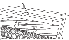
Servicing the Bedbar

Removing the Bedbar

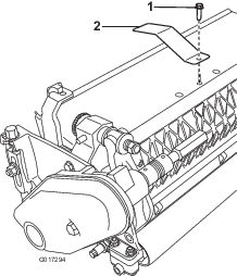
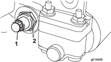
  1. Turn the bedbar-adjusting screw, counterclockwise, to back the bedknife away from the reel (Figure 19).

    g014641
  2. Back out the spring-tension nut until the washer is no longer tensioned against the bedbar (Figure 19).

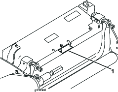
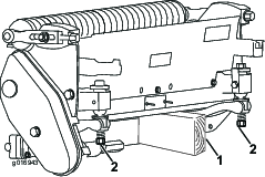
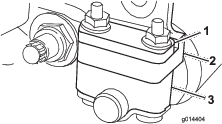
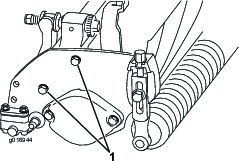
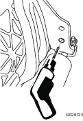
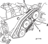
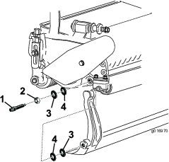
  3. On each side of the machine, loosen the locknut securing the bedbar bolt (Figure 20).

    g014409
  4. Remove each bedbar bolt allowing the bedbar to be pulled downward and removed from the machine bolt (Figure 20).

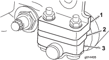
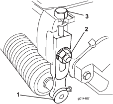
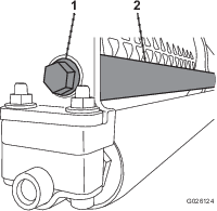
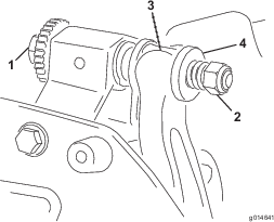
    Account for the 2 nylon and 2 stamped steel washers on each end of the bedbar (Figure 21).

    g016970
Close section

Assembling the Bedbar

  1. Install the bedbar, positioning the mounting ears between the washer and bedbar adjuster.

  2. Secure the bedbar to each side plate with the bedbar bolts (nuts on bolts) and 4 washers (8 total).

  3. Position a nylon washer on each side of the side plate boss. Place a steel washer outside each of the nylon washers (Figure 21).

  4. Torque the bedbar bolts to 27 to 36 N-m (240 to 320 inch-lb). Tighten the locknuts by hand until the outside steel washer stops rotating and there is no end play. The washers on the inside may have a gap.

    Important: Do not overtighten the locknuts or they will deflect the side plates.

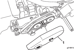
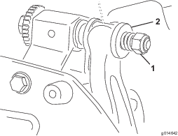
  5. Tighten the spring tension nut until the spring is collapsed, then back it off 1/2 turn (Figure 22).

    g014642
Close section
Close section

Backlapping the Reel

Danger

Contact with the reel or other moving parts can result in personal injury.

Keep your fingers, hands, and clothing away from the reels or other moving parts.

  • Stay away from the reel while backlapping.

  • Never use a short handled paint brush for backlapping. Handle assembly parts are available from your local authorized Toro distributor.

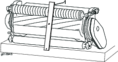
You can backlap the reels either by leaving the cutting unit on the traction unit or removing the cutting unit completely from the traction unit. If the cutting unit is left on the traction unit, move the hex coupler between the main drive and cutting unit drive to the decoupled position to prevent excessive wear to the reel brake.

  1. Position the machine on a clean, level surface.

  2. Shut off the machine as follows:

    • Gasoline units: shut off the engine and disconnect the spark-plug wire.

    • Electric units: turn off the machine and disconnect the battery connector (T-handle).

  3. Engage the parking brake.

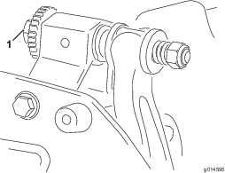
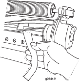
  4. Connect the backlapping machine to the cutting unit by connecting a 1/2 inch hex socket to the reel pulley output shaft on the left side of the cutting unit.

    Note: Additional instructions and procedures on Backlapping are available in the Toro Sharpening Reel and Rotary Mowers Manual (Form No. 80-300PT).

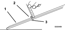
    Note: For a better cutting edge, run a file across the front face of the bedknife when the lapping operation is completed. This removes any burrs or rough edges that may have built up on the cutting edge. A very light file touch may be necessary on the top edge to break the burr off completely from the cutting edge.

    Note: If the cutting unit was left attached to the machine during backlapping, couple the hex shaft of the machine back to the cutting unit.

Close section
Close section