| Maintenance Service Interval | Maintenance Procedure |
|---|---|
| Before each use or daily |
|
Introduction
This rotary-blade, stand-on lawn mower is intended to be used by professional, hired operators or residential homeowners. It is designed primarily for cutting grass on well-maintained lawns on residential or commercial properties. It is not designed for cutting brush or for agricultural uses.
Read this information carefully to learn how to operate and maintain your product properly and to avoid injury and product damage. You are responsible for operating the product properly and safely.
You may contact Toro directly at www.Toro.com for product safety and operation training materials, accessory information, help finding a dealer, or to register your product.
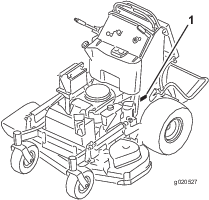
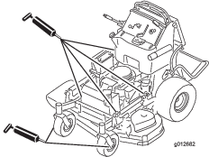
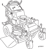
Whenever you need service, genuine Toro parts, or additional information, contact an Authorized Service Dealer or Toro Customer Service and have the model and serial numbers of your product ready. Figure 1 identifies the location of the model and serial numbers on the product. Write the numbers in the space provided.
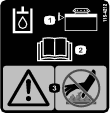
This manual identifies potential hazards and has safety messages identified by the safety-alert symbol (Figure 2), which signals a hazard that may cause serious injury or death if you do not follow the recommended precautions.

This manual uses 2 words to highlight information. Important calls attention to special mechanical information and Note emphasizes general information worthy of special attention.
Warning
CALIFORNIA
Proposition 65 Warning
The engine exhaust from this product contains chemicals known to the State of California to cause cancer, birth defects, or other reproductive harm.
This product complies with all relevant European directives; for details, please see the separate product specific Declaration of Conformity (DOC) sheet.
This spark ignition system complies with Canadian ICES-002
It is a violation of California Public Resource Code Section 4442 or 4443 to use or operate the engine on any forest-covered, brush-covered, or grass-covered land unless the engine is equipped with a spark arrester, as defined in Section 4442, maintained in effective working order or the engine is constructed, equipped, and maintained for the prevention of fire.
Safety
This machine has been designed in accordance with EN ISO 5395:2013.
Improper use or maintenance by the operator or owner can result in injury. To reduce the potential for injury, comply with these safety instructions and always pay attention to the safety alert symbol, which means Caution, Warning, or Danger—personal safety instruction. Failure to comply with the instruction may result in personal injury or death.
Safe Operating Practices
Training
-
Read the Operator's Manual and other training material.
-
If the operator(s) or mechanic(s) cannot read the manual language, it is the owner's responsibility to explain this material to them.
-
Become familiar with the safe operation of the equipment, operator controls, and safety signs.
-
All operators and mechanics should be trained. The owner is responsible for training the users.
-
Never let children or untrained people operate or service the equipment. Local regulations may restrict the age of the operator.
-
The owner/user can prevent and is responsible for accidents or injuries occurring to people, or damage to property.
Preparation
-
Evaluate the terrain to determine what accessories and attachments are needed to properly and safely perform the job. Only use accessories and attachments approved by the manufacturer.
-
Wear appropriate clothing; including safety glasses, long pants, substantial, slip-resistant footwear, gloves, and hearing protection. Tie back long hair and do not wear jewelry.
-
Inspect the area where the equipment is used, and remove all objects that can be thrown by the machine.
-
Use extra care when handling fuels. They are flammable and vapors are explosive.
-
Use only an approved container.
-
Do not remove the fuel cap or add fuel with the engine running. Allow the engine to cool before refueling. Do not smoke near the machine when the engine is running.
-
Do not refuel or drain the machine indoors.
-
-
Check that the operator's presence controls, safety switches, and shields are attached and functioning properly. Do not operate the machine unless they are functioning properly.
Operation
-
Lightning can cause severe injury or death. If lightning is seen, or thunder is heard in the area, do not operate the machine; seek shelter.
-
Do not run an engine in an enclosed area.
-
Operate only in well-lit areas, keeping away from holes and hidden hazards.
-
Ensure that all drives are in neutral and that the parking brake is engaged before starting engine. Start the engine only from the operator’s position.
-
Make sure that you have good footing while using this machine, especially when backing up. Reduced footing could cause slipping.
-
Slow down and use extra care on hillsides. Be sure to travel side to side on hillsides. Turf conditions can affect the stability of the machine. Use caution while operating near drop-offs.
-
Slow down and use caution when making turns and when changing directions on slopes.
-
Do not raise the mower deck with the blades running.
-
Do not operate the machine without the PTO shield or other guards securely in place. Be sure that all interlocks are attached, adjusted properly, and functioning properly.
-
Do not operate with the discharge deflector raised, removed or altered, unless you are using a grass catcher.
-
Do not change the engine governor setting or overspeed the engine.
-
Stop on level ground, disengage drives, engage the parking brake (if provided), shut off the engine before leaving the operator's position for any reason, including emptying the catchers or unclogging the chute.
-
Stop equipment and inspect the blades after striking objects or if an abnormal vibration occurs. Make the necessary repairs before resuming operations.
-
Keep your hands and feet away from the cutting unit.
-
Look behind and down before backing up to ensure a clear path.
-
Keep pets and bystanders away from an operating machine.
-
Slow down and use caution when making turns and crossing roads and sidewalks. Stop the blades if you are not mowing.
-
Be aware of the mower-discharge direction and do not point it at anyone.
-
Do not operate the mower under the influence of alcohol or drugs.
-
Use care when loading or unloading the machine into or from a trailer or truck.
-
Use care when approaching blind corners, shrubs, trees, or other objects that may obscure vision.
Safe Handling of Fuels
-
To avoid personal injury or property damage, use extreme care in handling gasoline. Gasoline is extremely flammable and the vapors are explosive.
-
Extinguish all cigarettes, cigars, pipes, and other sources of ignition.
-
Use only an approved fuel container.
-
Do not remove the fuel cap or add fuel with the engine running.
-
Allow the engine to cool before fueling.
-
Do not fuel the machine indoors.
-
Do not store the machine or fuel container where there is an open flame, spark, or pilot light, such as on a water heater or on other appliances.
-
Do not fill containers inside a vehicle, on a truck, or on a trailer bed with a plastic liner. Always place containers on the ground away from your vehicle before filling.
-
Remove equipment from the truck or trailer and fuel it on the ground. If this is not possible, then add fuel with such equipment as a portable container rather than from a fuel-dispenser nozzle.
-
Keep the nozzle in contact with the rim of the fuel tank or container opening at all times until fueling is complete.
-
Do not use a nozzle lock-open device.
-
If you spill fuel on clothing, change your clothing immediately.
-
Do not overfill the fuel tank. Replace the fuel cap and tighten securely.
Maintenance and Storage
-
Disengage drives, set the parking brake, stop the engine, and remove the key or disconnect spark-plug wire. Wait for all movement to stop before adjusting, cleaning, or repairing.
-
Park the machine on a level surface.
-
Clean grass and debris from the cutting unit, drives, mufflers, and engine to help prevent fires.
-
Clean up oil or fuel spills.
-
Let the engine cool before storing the machine.
-
Do not store fuel near flames or drain fuel indoors.
-
Do not allow untrained personnel to service the machine.
-
Use jack stands to support components when required.
-
Carefully release pressure from components with stored energy.
-
Disconnect the battery or remove the spark-plug wire before making any repairs. Disconnect the negative terminal first and the positive terminal last. Connect the positive terminal first and negative last.
-
Use care when checking the blades. Wrap the blade(s) or wear thickly padded gloves, and use caution when servicing them. Only replace blades; do not straighten or weld them.
-
Keep hands and feet away from moving parts. If possible, do not make adjustments with the engine running.
-
Keep all parts in good working condition and all hardware tightened. Replace all worn or damaged decals.
Hauling
-
Use care when loading or unloading the machine into a trailer or a truck.
-
Use full-width ramps for loading machine into a trailer or a truck.
-
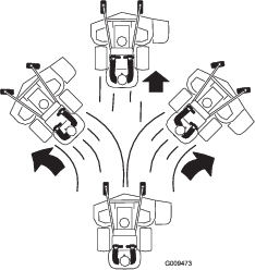
Tie the machine down securely using straps, chains, cable, or ropes. Both front and rear straps should be directed down and outward from the machine.
Toro Mower Safety
The following list contains safety information specific to Toro products and other safety information you must know.
This product is capable of amputating hands and feet, and throwing objects. Always follow all safety instructions to avoid serious injury or death.
This product is designed for cutting and recycling grass, or, when equipped with a grass bagger, for catching cut grass. Any use for purposes other than these could prove dangerous to the user and bystanders.
General Operation
-
Be sure that the area is clear of bystanders before mowing. Stop the machine if anyone enters the area.
-
Do not touch equipment or attachment parts which may be hot from operation. Allow all of the parts to cool before attempting to maintain, adjust, or service the machine.
-
Use only Toro-approved attachments. Warranty may be voided if used with any unapproved attachments.
-
Check carefully for overhead clearances (i.e. branches, doorways, electrical wires, etc.) before operating under any objects, and do not contact them.
-
Slow down before making turns and use extra caution.
-
Use caution when riding the platform over curbs, rocks, roots, or other obstructions.
-
Look behind and down before backing up to ensure a clear path. Use extra care when operating in reverse.
-
Do not jerk the controls; use a steady motion.
-
When loading or unloading the machine, use one full-width ramp that is wide enough to extend beyond the width of the machine.
-
Do not carry passengers.
-
Do not carry equipment on the machine.
Slope Operation
All slopes and ramps require extra caution. If you feel uneasy on a slope, do not mow it.
-
Remove obstacles such as rocks, tree limbs, etc. from the mowing area.
-
Watch for holes, ruts or bumps. Tall grass can hide obstacles.
-
Use caution near drop-offs, ditches, or embankments. The machine could suddenly turn over if a wheel goes over the edge of a cliff or ditch, or if an edge caves in.
-
Use extra care with grass catchers or other attachments. These can change the stability of the machine.
-
Keep all movement on slopes slow and gradual.
-
Do not make sudden changes in speed or direction.
-
Mow slopes side to side.
-
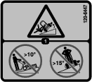
Do not mow slopes greater than 15 degrees.
Service
-
Do not store the machine or a fuel container inside where there is an open flame, such as near a water heater or furnace.
-
Keep the nuts and bolts tight, especially the blade-attachment bolts.
-
Never remove or tamper with safety devices. Check their proper operation regularly. Never do anything to interfere with the intended function of a safety device or to reduce the protection provided by a safety device.
-
To best protect your investment and maintain optimal performance of your Toro equipment, count on Toro genuine parts. When it comes to reliability, Toro delivers replacement parts designed to the exact engineering specifications of our equipment. For peace of mind, insist on Toro genuine parts.
-
Check brake operation frequently. Adjust and service as required.
Sound Pressure
Model 74534TE has a sound pressure level at the operator’s ear of 88 dBA, which includes an Uncertainty Value (K) of 1 dBA.
Model 74536TE has a sound pressure level at the operator’s ear of 86 dBA, which includes an Uncertainty Value (K) of 1 dBA.
The sound pressure level was determined according to the procedures outlined in EN ISO 5395:2013.
Sound Power
Model 74534TE has a guaranteed sound power level of 100 dBA, which includes an Uncertainty Value (K) of 1 dBA.
Model 74536TE has a guaranteed sound power level of 100 dBA, which includes an Uncertainty Value (K) of 1 dBA.
The sound power level was determined according to the procedures outlined in ISO 11094.
Vibration Level for Model 74534TE
Hand-Arm
Measured vibration level for right hand = 0.8 m/s2
Measured vibration level for left hand = 0.6 m/s2
Uncertainty Value (K) = 0.4 m/s2
Measured values were determined according to the procedures outlined in EN ISO 5395:2013.
Whole Body
Measured vibration level = 0.79 m/s2
Uncertainty Value (K) = 0.39 m/s2
Measured values were determined according to the procedures outlined in EN ISO 5395:2013.
Vibration Level for Model 74536TE
Hand-Arm
Measured vibration level for right hand = 1.1 m/s2
Measured vibration level for left hand = 1.1 m/s2
Uncertainty Value (K) = 0.6 m/s2
Measured values were determined according to the procedures outlined in EN ISO 5395:2013.
Whole Body
Measured vibration level = 0.79 m/s2
Uncertainty Value (K) = 0.39 m/s2
Measured values were determined according to the procedures outlined in EN ISO 5395:2013.
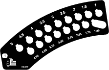
Slope Indicator
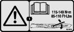
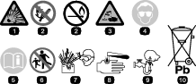
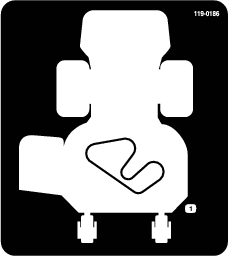
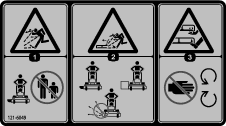
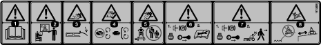
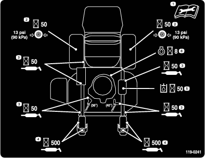
Safety and Instructional Decals
 |
Safety decals and instructions are easily visible to the operator and are located near any area of potential danger. Replace any decal that is damaged or lost. |


Product Overview
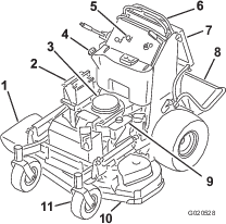
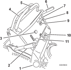
Become familiar with all the controls (Figure 5) before you start the engine and operate the machine.
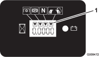
Hour Meter
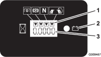
The hour meter records the number of hours the engine has operated. It operates when the engine is running. Use these times for scheduling regular maintenance (Figure 6).
Fuel Gauge
The fuel gauge is located on the top, middle of the tank (Figure 5).
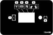
Safety-interlock Indicators
There are symbols on the hour meter and indicate with a black triangle that the interlock component is in the correct position (Figure 6).
Battery-indicator Light
If the ignition key is turned to the ON position for a few seconds, the battery voltage be displays in the area where the hours are normally displayed.
The battery light turns on when the ignition is turned on and when the charge is below the correct operating level (Figure 6).
Throttle Control
The throttle control is variable between the FAST and SLOW positions.
Choke
Use the choke to start a cold engine.
Blade-Control Switch (PTO)
Use the blade-control switch (PTO) to engage the electric clutch to drive the mower blades with either motion-control lever in the center, unlocked position (Figure 5). Pull the switch up to engage the blades and release. To disengage the blades, push the blade-control switch (PTO) down, or move or release the motion-control levers into the NEUTRAL-LOCK position.
Ignition Switch
Use the ignition switch to start the mower engine (Figure 5). The switch has 3 positions: OFF, RUN, and START.
Motion-control Levers
The motion-control levers are used to drive the machine forward, reverse, and turn either direction.
Fuel-Shutoff Valve
Close the fuel-shutoff valve (located behind the operator cushion on the right hand side of fuel tank) when transporting or storing the mower.
Attachments/Accessories
A selection of Toro approved attachments and accessories is available for use with the machine to enhance and expand its capabilities. Contact your Authorized Service Dealer or Distributor or go to www.Toro.com for a list of all approved attachments and accessories.
Note: Specifications and design are subject to change without notice.
| Cutting width | 91 cm (36 inches) |
| Width with deflector down | 131 cm (52 inches) |
| Length with platform down | 188 cm (74 inches) |
| Length with platform up | 155 cm (61 inches) |
| Height | 122 cm (48 inches) |
| Weight | 343 kg (756 lb) |
| Cutting width | 102 cm (40 inches) |
| Width with deflector down | 142 cm (56 inches) |
| Length with platform down | 178 cm (70 inches) |
| Length with platform up | 145 cm (57 inches) |
| Height | 122 cm (48 inches) |
| Weight | 351 kg (773 lb) |
Operation
Think Safety First
Carefully read all the safety instructions and decals in the safety section. Knowing this information could help you or bystanders avoid injury.
Caution
This machine produces sound levels in excess of 85 dBA at the operator's ear and can cause hearing loss from extended periods of exposure.
Wear hearing protection when operating this machine.
Use protective equipment for your eyes, ears, and feet.

Adding Fuel
-
For best results, use only clean, fresh (less than 30 days old), unleaded gasoline with an octane rating of 87 or higher ((R+M)/2 rating method).
-
Ethanol: Gasoline with up to 10% ethanol (gasohol) or 15% MTBE (methyl tertiary butyl ether) by volume is acceptable. Ethanol and MTBE are not the same. Gasoline with 15% ethanol (E15) by volume is not approved for use. Never use gasoline that contains more than 10% ethanol by volume, such as E15 (contains 15% ethanol), E20 (contains 20% ethanol), or E85 (contains up to 85% ethanol). Using unapproved gasoline may cause performance problems and/or engine damage which may not be covered under warranty.
-
Do not use gasoline containing methanol.
-
Do not store fuel either in the fuel tank or fuel containers over the winter unless you use a fuel stabilizer.
-
Do not add oil to gasoline.
Danger
In certain conditions, gasoline is extremely flammable and highly explosive. A fire or explosion from gasoline can burn you and others and can damage property.
-
Fill the fuel tank outdoors, in an open area, when the engine is cold. Wipe up any gasoline that spills.
-
Never fill the fuel tank inside an enclosed trailer.
-
Do not fill the fuel tank completely full. Add gasoline to the fuel tank until the level is 6 to 13 mm (1/4 to 1/2 inch) below the bottom of the filler neck. This empty space in the tank allows gasoline to expand.
-
Never smoke when handling gasoline, and stay away from an open flame or where gasoline fumes may be ignited by a spark.
-
Store gasoline in an approved container and keep it out of the reach of children. Never buy more than a 30-day supply of gasoline.
-
Do not operate without entire exhaust system in place and in proper working condition.
Danger
In certain conditions during fueling, static electricity can be released causing a spark, which can ignite the gasoline vapors. A fire or explosion from gasoline can burn you and others and can damage property.
-
Always place gasoline containers on the ground away from your vehicle before filling.
-
Do not fill gasoline containers inside a vehicle or on a truck or trailer bed because interior carpets or plastic truck bed liners may insulate the container and slow the loss of any static charge.
-
When practical, remove gas-powered equipment from the truck or trailer and refuel the equipment with its wheels on the ground.
-
If this is not possible, then refuel such equipment on a truck or trailer from a portable container rather than from a gasoline-dispenser nozzle.
-
If you must use a gasoline-dispenser nozzle must be used, keep the nozzle in contact with the rim of the fuel tank or container opening at all times until fueling is complete.
Warning
Gasoline is harmful or fatal if swallowed. Long-term exposure to vapors can cause serious injury and illness.
-
Avoid prolonged breathing of vapors.
-
Keep face away from nozzle and gas tank or conditioner bottle opening.
-
Avoid contact with skin; wash off spills with soap and water.
Using Stabilizer/Conditioner
Use a fuel stabilizer/conditioner in the machine to provide the following benefits:
-
Keeps gasoline fresh during storage of 90 days or less. For longer storage, drain the fuel tank.
-
Cleans the engine while it runs
-
Eliminates gum-like varnish buildup in the fuel system, which causes hard starting
Important: Do not use fuel additives containing methanol or ethanol.
Add the correct amount of gas stabilizer/conditioner to the gas.
Note: A fuel stabilizer/conditioner is most effective when mixed with fresh gasoline. To minimize the chance of varnish deposits in the fuel system, use fuel stabilizer at all times.
Filling the Fuel Tank
-
Park the machine on level ground.
-
Shut the engine off and set the parking brake.
-
Clean around the fuel-tank cap and remove the cap.
-
Fill the fuel tank to the bottom of the filler neck.
Note: Do not fill the fuel tank completely full. The empty space in the tank allows the gasoline to expand.
-
Install the fuel-tank cap securely. Wipe up any gasoline that may have spilled.
Checking the Engine-Oil Level
Before you start the engine and use the machine, check the oil level in the engine crankcase; refer to Checking the Engine-Oil Level.
Breaking in a New Machine
New engines take time to develop full power. Mower decks and drive systems have higher friction when new, placing additional load on the engine. Allow 40 to 50 hours of break-in time for new machines to develop full power and best performance.
Operating the Parking Brake
Always set the parking brake when you stop the machine or leave it unattended. Before each use, check the parking brake for proper operation.
If the parking brake does not hold securely, adjust it; refer to Adjusting the Brakes.
Caution
Children or bystanders may be injured if they move or attempt to operate the machine while it is unattended.
Always remove the ignition key and set the parking brake when leaving the machine unattended.
Setting the Parking Brake
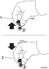
Pull the parking-brake lever rearward into the ENGAGED position (Figure 8).
Releasing the Parking Brake
Push the parking-brake lever forward (Figure 8).
Operating the Mower-Blade-Control Switch (PTO)
The blade-control switch (PTO) is used in conjunction with the right motion-control lever to engage and disengage the mower blades.
Engaging the Mower Blades (PTO)
-
To engage the mower blades, move the right motion-control lever to the center, unlocked position.
-
Pull the blade-control switch (PTO) up and release it while holding down the right motion-control lever in the center, unlocked position.

Operating the Throttle
The throttle control moves between FAST and SLOW positions (Figure 12).
Always use the FAST position when engaging the mower blades with the blade-control switch (PTO).

Operating the Choke
Operating the Ignition Switch
Important: Do not engage the starter for more than 5 seconds at a time. If the engine fails to start, wait 15 seconds between attempts. Failure to follow these instructions can burn out the starter motor.
Note: You may need to repeat the cycle for starting the engine when you start it for the first time after you have filled a completely empty fuel system with fuel.
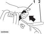
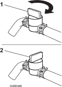
Using the Fuel-Shutoff Valve
The fuel-shutoff valve is located behind the right side of the operator cushion.
Close the fuel-shutoff valve for transport, maintenance, and storage (Figure 16).
Ensure that the fuel-shutoff valve is open when starting the engine.
Starting and Stopping the Engine
Starting the Engine
Important: Do not engage the starter for more than 5 seconds at a time. If the engine fails to start, wait 15 seconds between attempts. Failure to follow these instructions can burn out the starter motor.
Note: A warm or hot engine may not require choking.
Note: You may need to repeat the cycle for starting the engine when you start it for the first time after you have filled a completely empty fuel system with fuel.
Stopping the Engine
Caution
Children or bystanders may be injured if they move or attempt to operate the tractor while it is unattended.
Always remove the ignition key and set the parking brake when leaving the machine unattended, even if just for a few minutes.
Important: Make sure that the fuel-shutoff valve is closed before transporting or storing the machine, as fuel leakage may occur. Before storing the machine, pull wire off spark plug(s) to prevent possibility of accidental starting.
Using the Safety-Interlock System
Caution
If the safety-interlock switches are disconnected or damaged, the machine could operate unexpectedly, causing personal injury.
-
Do not tamper with the interlock switches.
-
Check the operation of the interlock switches daily and replace any damaged switches before operating the machine.
Understanding the Safety-Interlock System
The safety-interlock system is designed to prevent the mower blades from rotating unless 1 of the following occur:
-
You move the right motion-control lever to the center, unlocked position.
-
The blade-control switch (PTO) is engaged.
The safety-interlock system is designed to stop the mower blades if you move or release the right motion-control lever into the NEUTRAL-LOCK position.
The hour meter has symbols to notify you when the interlock component is in the correct position. When the component is in the correct position, a triangle lights up in the corresponding square.
Testing the Safety-Interlock System
Test the safety-interlock system before you use the machine each time.
Note: If the safety system does not operate as described below, have an Authorized Service Dealer repair the safety system immediately.
-
Start the engine; refer to Starting the Engine.
-
Set the parking brake.
-
Move the right motion-control lever to the center, unlocked position.
Note: The blades should not rotate.
-
Move the motion-control levers forward.
Note: The engine should stop running.
-
Start the engine and release the parking brake.
-
Move the right motion-control lever to the center, unlocked position.
-
Continue holding the right motion-control lever in the center, unlocked position, pull up the blade-control switch (PTO), and release.
Note: The clutch should engage and the mower blades should rotate.
-
Move or release the right motion-control lever into the neutral-lock position.
Note: The blades should stop rotating and the engine should continue to run.
-
Push the blade-control switch down and move the right motion-control lever to the center, unlocked position.
-
Continue holding the right motion-control lever in the center, unlocked position, pull up on the blade-control switch (PTO), and release.
Note: The clutch should engage and the mower blades shouldrotate.
-
Push the blade-control switch (PTO) down to the OFF position.
Note: The blades should stop rotating.
-
With the engine running, pull up the blade-control switch (PTO) and release it without holding right motion-control lever to the center, unlocked position.
Note: The blades should not rotate.
Warning
The operator platform is heavy and may cause injury when lowering and raising the operator platform. Carefully lower or raise the operator platform, as suddenly dropping it could injure you.
-
Do not put your hands or fingers in the platform-pivot area when lowering or raising the operator platform.
-
Make sure that the platform is supported when you pull the latch pin out.
-
Make sure that the latch secures the platform when folding it up. Push it tight against the cushion for the latch pin to lock into place.
-
Keep bystanders away when raising or lowering the platform.
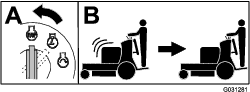
Operating the Platform
You can use the machine with the platform in the up or down position. It is your preference on which position to use.
Operating the Machine with the Platform Up
Operate the machine with the platform up for the following conditions:
-
Mowing near drop-offs
-
Mowing small areas where the machine is too large
-
Areas with low, over-hanging branches or obstacles
-
Loading the machine for transport
-
Driving up slopes
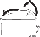
To raise the platform, pull the back of the platform up so that the latch pin and knob lock it into place. Push it tight against the cushion for the latch pin to lock it into place.
Operating the Machine with the Platform Down
Operate the machine with the platform down for the following conditions:
-
Mowing most areas
-
Driving across slopes
-
Driving down slopes
To lower the platform, push the platform forward against the cushion to release pressure on the latch pin, pull the knob out, and lower the platform (Figure 20).
Driving Forward or Backward
The throttle control regulates the engine speed as measured in rpm (revolutions per minute). Place the throttle control in the FAST position for best performance. Always operate in the full-throttle position when mowing.
Caution
The machine can spin very rapidly, and you may lose control of machine, causing personal injury to you and damage to machine.
Slow the machine down before making sharp turns.
Driving Forward
-
Release the parking brake; refer to Releasing the Parking Brake.
-
Move the right motion-control lever to the center, unlocked position.
-
To go forward, move the speed-control lever to the desired speed.
-
Slowly push the motion-control levers forward (Figure 22).
Note: The engine stops if you move a motion-control lever with the parking brake engaged.
Note: The farther you move the motion-control levers in either direction, the faster the machine moves in that direction.
Note: To stop, pull the motion-control levers back to the NEUTRAL position.
Driving Backward
-
Move the right motion-control lever to the center, unlocked position.
-
Slowly pull the motion-control levers rearward (Figure 23).

Stopping the Machine
To stop the machine, move the motion-control levers to NEUTRAL, move the right motion-control lever into the NEUTRAL-LOCK position, disengage the power takeoff (PTO), and turn the ignition key to the OFF position.
Set the parking brake when you leave the machine; refer to Setting the Parking Brake. Remove the key from the ignition switch.
Caution
Children or bystanders may be injured if they move or attempt to operate the machine.
Always remove the ignition key and set the parking brake when leaving the machine unattended.
Pushing the Machine by Hand
The bypass valves allow the machine to be pushed by hand without the engine running.
Important: Always push the machine by hand. Never tow the machine, because hydraulic damage may occur.
-
Disengage the PTO, move the motion-control levers to the NEUTRAL-LOCKED position, and set the parking brake.
-
Lower the mower deck to the lowest height of cut (HOC).
Note: This allows access to the bypass valves.
-
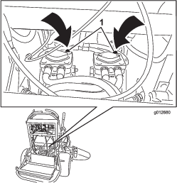
Open the bypass valve on both pumps by turning them counterclockwise 1 to 2 turns (Figure 24).
Note: This allows hydraulic fluid to bypass the pumps and the wheels to turn.
Note: Rotate the bypass valves a maximum of 2 turns so that the valve does not come out of the body, causing fluid to run out.
-
Release the parking brake.
-
Push the machine to the desired location.
-
Set the parking brake.
-
Close the bypass valves but do not overtighten them.
-
Torque the valves to 12 to 15 N∙m (110 to 130 in-lb).
Important: Do not start or operate the machine with the bypass valves open. Damage to system may occur.
Transporting the Machine
Use a heavy-duty trailer or truck to transport the machine. Ensure that the trailer or truck has all necessary brakes, lighting, and marking as required by law. Please carefully read all the safety instructions.
-
Raise the platform of the machine before driving up onto the trailer or truck.
-
If using a trailer, connect it to the towing vehicle and connect the safety chains.
-
If applicable, connect the trailer brakes.
-
Load the machine onto the trailer or truck.
-
Shut off the engine, remove the key, set the brake, and close the fuel valve.
-
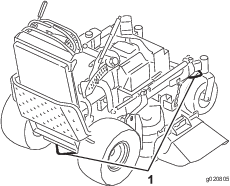
Use the metal tie-down loops on the machine to securely fasten the machine to the trailer or truck with straps, chains, cable, or ropes (Figure 25).
Loading the Machine
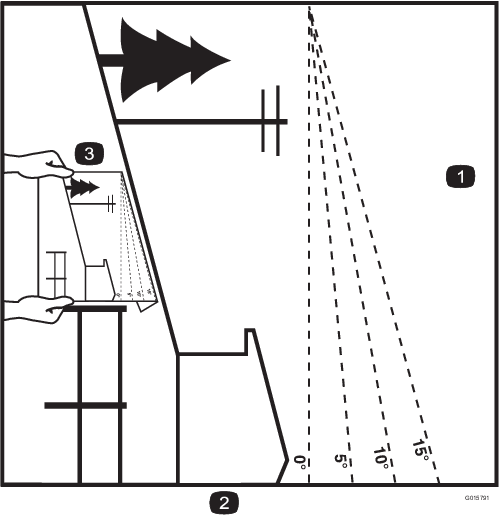
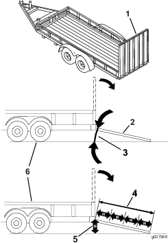
Use extreme caution when loading or unloading machines onto a trailer or a truck. Use a full-width ramp that is wider than the machine for this procedure. Back the machine up the ramp and walk it forward down the ramp (Figure 26).

Important: Do not use narrow individual ramps for each side of the machine.
Ensure that the ramp is long enough so that the angle with the ground does not exceed 15 degrees (Figure 27). On flat ground, this requires a ramp to be at least 4 times as long as the height of the trailer or truck bed to the ground. A steeper angle may cause mower components to get caught as the machine moves from the ramp to the trailer or truck. Steeper angles may also cause the machine to tip or lose control. If you are loading the machine on or near a slope, position the trailer or truck so that it is on the down side of the slope and the ramp extends up the slope. This minimizes the ramp angle.
Warning
Loading a machine onto a trailer or truck increases the possibility of tip-over and could cause serious injury or death.
-
Use extreme caution when operating a machine on a ramp.
-
Use only a full-width ramp; do not use individual ramps for each side of the machine.
-
Do not exceed a 15-degree angle between the ramp and the ground or between the ramp and the trailer or truck.
-
Ensure the length of ramp is at least 4 times as long as the height of the trailer or truck bed to the ground. This will ensure that ramp angle does not exceed 15 degrees on flat ground.
-
Back the machine up ramps and walk it forward down ramps.
-
Avoid sudden acceleration or deceleration while driving the machine on a ramp, as this could cause a loss of control or a tip-over situation.
Side Discharging or Mulching the Grass
This mower has a hinged grass deflector that disperses clippings to the side and down toward the turf.
Danger
Without the grass deflector, discharge cover, or complete grass catcher assembly mounted in place, you and others are exposed to blade contact and thrown debris. Contact with rotating mower blade(s) and thrown debris cause injury or death.
-
Do not remove the grass deflector from the mower, because the grass deflector routes material down toward the turf. If the grass deflector is ever damaged, replace it immediately.
-
Never put your hands or feet under the mower.
-
Never try to clear the discharge area or mower blades unless you release the bail and the power takeoff (PTO) is off. Rotate the ignition key to the OFF position. Also remove the key and disconnect the wire(s) off the spark plug(s).
Adjusting the Height of Cut
The height of cut can be adjusted from 25 to 127 mm (1 to 5 inches) in 6 mm (1/4 inch) increments.
-
Move the height-of-cut lever to the transport position (all the way up).
-
Rotate the pin 90 degrees and remove it from the height-of-cut bracket.
-
Select a hole in the height-of-cut bracket corresponding to the height-of-cut desired and insert the pin (Figure 28).
-
Push the button on top and lower the height-of-cut lever to the pin (Figure 28).
Adjusting the Flow Baffle
You can adjust the mower-discharge flow for different types of mowing conditions. Position the cam lock and baffle to provide the best quality of cut.
-
Disengage the PTO, move the motion-control levers to the NEUTRAL-LOCK position, and set the parking brake.
-
Shut off the engine, remove the key, and wait for all moving parts to stop before leaving the operating position.
-
To adjust the baffle, loosen the nut (Figure 29).
-
Adjust the baffle and nut in the slot to the desired discharge flow and tighten the nut.
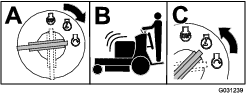
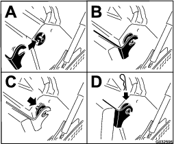
Positioning the Flow Baffle
The following figures are only for recommended use. Adjustments vary by grass type, moisture content, and the height of the grass.
Note: If the engine power draws down, and the mower ground speed is the same, open up the baffle.
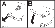
Position A
This is the full, rear position (see Figure 30). Use this position for the following:
-
In short, light grass mowing conditions
-
In dry conditions
-
Smaller grass clippings
-
Propels grass clippings farther away from the mower
Position B
Use this position when bagging (Figure 31).
Position C
This is the full, open position (Figure 32). Use for this position for the following:
-
In tall, dense grass mowing conditions
-
In wet conditions
-
Lowers the engine-power consumption
-
Allows increased ground speed in heavy conditions
Using Counterweights
-
Install weights to improve handling, balance and improve performance.
-
You can add or remove weights to create optimized performance under different mowing conditions and for your preference.
-
Add or remove 1 at a time until you achieve the desired handing and balance.
Note: Contact an Authorized Service Dealer to order a Weight Kit.
Warning
Excessive weight changes can affect the handling and operation of the machine. This could cause serious injury to you or bystanders.
-
Make weight changes in small increments only.
-
Evaluate the mower after each weight change to ensure the machine can be operated safely.
Maintenance
Note: Determine the left and right sides of the machine from the normal operating position.
Recommended Maintenance Schedule(s)
| Maintenance Service Interval | Maintenance Procedure |
|---|---|
| After the first 8 hours |
|
| Before each use or daily |
|
| Every 25 hours |
|
| Every 50 hours |
|
| Every 100 hours |
|
| Every 200 hours |
|
| Every 250 hours |
|
| Every 300 hours |
|
| Every 500 hours |
|
| Before storage |
|
| Yearly |
|
Important: Refer to your engine owner’s manual for additional maintenance procedures.
Caution
If you leave the key in the ignition switch, someone could accidently start the engine and seriously injure you or other bystanders.
Remove the key from the ignition and disconnect the spark-plug wires from the spark plugs before you do any maintenance. Set the wires aside so that they do not accidentally contact the spark plugs.
Pre-Maintenance Procedures
Raising the Mower for Access
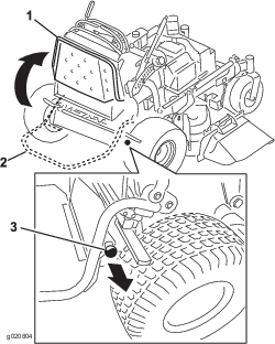
You can raise the front of the mower and support it on its back for access under the machine for maintenance.
-
Raise the platform; refer to Operating the Platform.
-
Remove the battery; refer to Removing the Battery.
-
Drain the fuel from the fuel tank; refer to Draining the Fuel Tank.
-
Remove the cap of the hydraulic tank and place a piece of plastic over the opening and install the hydraulic cap.
Note: This seals the hydraulic tank and prevents it from leaking out.
-
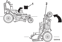
With 2 people, raise the front of the mower so that it rests on the drive tires and the platform in the up position.
-
Perform any maintenance on the machine.
-
With 2 people, lower the front of the mower to the ground.
-
Remove the plastic under the hydraulic-tank cap.
-
Install the battery for the machine.
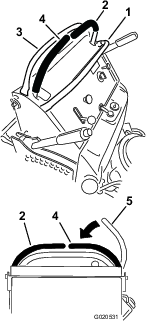
Releasing the Cushion for Rear Access
You can release the cushion for rear access to the machine for maintenance or adjustment.
-
Lower the platform.
-
Remove the hairpin cotters on each side of the cushion.
-
Slide the large washers with plastic bushings to the inside.
-
Remove the cushion and lower it to the platform.
-
Perform any maintenance or adjustment on the machine.
-
Raise the cushion and slide it onto the pins on both sides of the machine (Figure 36).
-
Slide the large washers with plastic bushings into the cushion bracket and secure them with a hairpin-cotter pin (Figure 36).
Lubrication
Grease with No. 2 lithium or molybdenum grease.
Lubricating the Machine
| Maintenance Service Interval | Maintenance Procedure |
|---|---|
| Every 50 hours |
|
-
Disengage the PTO and set the parking brake.
-
Shut off the engine, remove the key, and wait for all moving parts to stop before leaving the operating position.
-
Clean the grease fittings with a rag.
Note: Make sure to scrape any paint off the front of the fitting(s).
-
Connect a grease gun to the fitting.
-
Pump grease into the fittings until grease begins to ooze out of the bearings.
-
Wipe up any excess grease.
Use the following graphics for locating the grease points.
Greasing the Front Caster Pivots
| Maintenance Service Interval | Maintenance Procedure |
|---|---|
| Yearly |
|
-
Remove the dust cap and adjust the caster pivots; refer to Adjusting the Caster-Pivot Bearing.
Note: Keep the dust cap off until greasing is done.
-
Remove the hex plug.
-
Thread a grease fitting into the hole.
-
Pump grease into the fitting until it oozes out around the top bearing.
-
Remove the grease fitting in the hole.
-
Install the hex plug and cap.
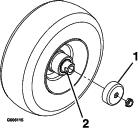
Lubricating the Caster-Wheel Hubs
| Maintenance Service Interval | Maintenance Procedure |
|---|---|
| Yearly |
|
-
Shut off the engine, wait for all moving parts to stop, engage the parking brake, and remove the key.
-
Remove the caster wheel from the caster forks.
-
Remove the seal guards from the wheel hub.
-
Remove a spacer nut from the axle assembly in the caster wheel.
Note: Thread-locking adhesive has been applied to lock the spacer nuts to the axle. Remove the axle (with the other spacer nut still assembled to it) from the wheel assembly.
-
Pry out the seals and inspect bearings for wear or damage, and replace if necessary.
-
Pack the bearings with a general-purpose grease.
-
Insert 1 bearing and 1 seal into the wheel.
Note: Replace the seals.
-
If the axle assembly has had both spacer nuts removed (or broken loose), apply a thread-locking adhesive to 1 spacer nut and thread it onto the axle with the wrench flats facing outward.
Note: Do not thread the spacer nut all the way onto the end of the axle. Leave approximately 3 mm (1/8 inch) from the outer surface of the spacer nut to the end of the axle inside the nut.
-
Insert the assembled nut and axle into the wheel on the side of the wheel with the new seal and bearing.
-
With the open end of the wheel facing up, fill the area inside the wheel around the axle full of general-purpose grease.
-
Insert the second bearing and the new seal into the wheel.
-
Apply a thread-locking adhesive to the second spacer nut and thread it onto the axle with the wrench flats facing outward.
-
Torque the nut to 8 to 9 N∙m (71 to 80 in-lb), loosen it, then torque it to 2 to 3 N∙m (20 to 25 in-lb).
Note: Make sure that the axle does not extend beyond either nut.
-
Install the seal guards over the wheel hub and insert the wheel into the caster fork.
-
Install the caster bolt and tighten the nut fully.
Important: To prevent seal and bearing damage, check the bearing adjustment often by spinning the caster tire. The tire should not spin freely (more than 1 or 2 revolutions) or have any side play. If the wheel spins freely, adjust the torque on the spacer nut until there is a slight amount of drag and apply thread-locking adhesive.
Engine Maintenance
Servicing the Air Cleaner
| Maintenance Service Interval | Maintenance Procedure |
|---|---|
| Every 300 hours |
|
Service Interval/Specification
Inspect the foam and paper elements and replace them if they are damaged or excessively dirty.
Note: Service the air cleaner more frequently (every few operating hours) if the operating conditions are extremely dusty or sandy.
Important: Do not oil the foam or paper element.
Removing the Foam and Paper Elements
-
Disengage the PTO and set the parking brake.
-
Shut off the engine, remove the key, and wait for all moving parts to stop before leaving the operating position.
-
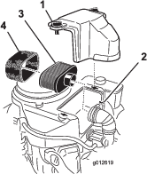
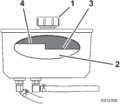
Clean around the air cleaner to prevent dirt from getting into the engine and causing damage (Figure 41).
-
Loosen the cover knobs and remove the air-cleaner cover (Figure 41).
-
Loosen the hose clamp and remove the air-cleaner assembly (Figure 41).
-
Carefully pull the foam element off the paper element (Figure 41).
Cleaning the Foam Air-Cleaner Element
| Maintenance Service Interval | Maintenance Procedure |
|---|---|
| Every 25 hours |
|
-
Wash the foam element in liquid soap and warm water. When the element is clean, rinse it thoroughly.
-
Dry the element by squeezing it in a clean cloth.
Important: Replace the foam element if it is torn or worn.
Servicing the Paper Air-Cleaner Element
| Maintenance Service Interval | Maintenance Procedure |
|---|---|
| Every 50 hours |
|
| Every 200 hours |
|
-
Clean the paper element by tapping gently to remove dust.
Note: If it is very dirty, replace the paper element with a new one (Figure 41).
-
Inspect the element for tears, an oily film, or damage to the rubber seal.
Installing the Foam and Paper Elements
Important: To prevent engine damage, always operate the engine with the complete foam and paper air-cleaner assembly installed.
Servicing the Engine Oil
| Maintenance Service Interval | Maintenance Procedure |
|---|---|
| After the first 8 hours |
|
| Before each use or daily |
|
| Every 100 hours |
|
| Every 200 hours |
|
Note: There are different oil capacities for the different models listed in this manual. Ensure that the correct amount of oil is used.
Important: Add 80% of the oil and then gradually fill it to the Full mark on the dipstick.
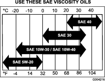
Oil Type: Detergent oil (API service SF, SG, SH, SJ or SL)
Engine Oil Capacity: 1.7 L (58 oz) with the filter removed; 1.5 L (51 oz) without the filter removed
Viscosity: Refer to the table below:
Checking the Engine-Oil Level
Note: Check the oil when the engine is cold.
Warning
Contact with hot surfaces may cause personal injury.
Keep hands, feet, face, clothing and other body parts away the muffler and other hot surfaces.
Important: Do not overfill the crankcase with oil because damage to the engine may result. Do not run engine with oil below the low mark because the engine may be damaged.
-
Disengage the PTO, move the motion-control levers to the NEUTRAL-LOCK position, and set the parking brake.
-
Shut off the engine, remove the key, and wait for all moving parts to stop before leaving the operating position (Figure 43).

Changing the Engine Oil
Note: Dispose of the used oil at a recycling center.
-
Park the machine so that the drain side is slightly lower than the opposite side to assure the oil drains completely.
-
Disengage the PTO, move the motion-control levers to the NEUTRAL-LOCK position and set the parking brake.
-
Shut off the engine, remove the key, and wait for all moving parts to stop before leaving the operating position (Figure 44).
-
Change the engine oil as shown in Figure 44.
-
Slowly pour approximately 80% of the specified oil into the filler tube and slowly add the additional oil to bring it to the Full mark (Figure 45).
Changing the Engine-Oil Filter
Note: Change the engine-oil filter more frequently when operating conditions are extremely dusty or sandy.
-
Drain the oil from the engine; refer to Changing the Engine Oil.
-
Place a rag under the oil filter to soak up any spilled oil.
Important: Spilled oil may drain under the engine and onto the clutch. Oil spilled on the clutch may damage the clutch, cause the blades to stop slowly when the clutch is in the OFF position, and cause the clutch to slip when the clutch is switched to the ON position. Wipe up any spilled oil.
-
Change the engine-oil filter (Figure 46).
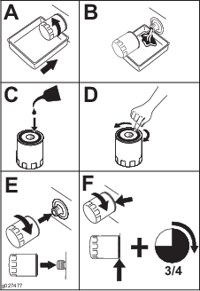
Note: Ensure that the oil-filter gasket touches the engine and then an extra 3/4 turn is completed.
-
Fill the crankcase with the proper type of new oil; refer to Changing the Engine Oil.
Servicing the Spark Plug
| Maintenance Service Interval | Maintenance Procedure |
|---|---|
| Every 100 hours |
|
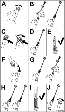
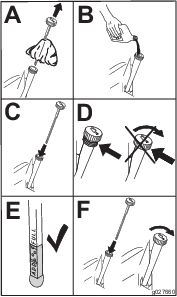
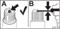
Make sure that the air gap between the center and side electrodes is correct before installing the spark plug.
Use a spark plug wrench for removing and installing the spark plug(s) and a gapping tool/feeler gauge to check and adjust the air gap. Install a new spark plug(s) if necessary.
Type for all Engines: NGK® BPR4ES or equivalent
Air Gap: 0.75 mm (0.03 inch)
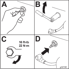
Removing the Spark Plug
-
Disengage the PTO, move the motion-control levers to the NEUTRAL-LOCK position, and set the parking brake.
-
Shut off the engine, remove the key, and wait for all moving parts to stop before leaving the operating position.
-
Remove the spark plug as shown in Figure 47.

Checking the Spark Plug
Important: Do not clean the spark plug(s). Always replace the spark plug(s) when it has a black coating, worn electrodes, an oily film, or cracks.
If you see light brown or gray on the insulator, the engine is operating properly. A black coating on the insulator usually means the air cleaner is dirty.
Set the gap to 0.75 mm (0.03 inch).
Installing the Spark Plug
Checking the Spark Arrester
If Equipped
| Maintenance Service Interval | Maintenance Procedure |
|---|---|
| Every 50 hours |
|
Warning
Hot exhaust-system components may ignite gasoline vapors even after you shut off the engine. Hot particles exhausted during engine operation may ignite flammable materials, resulting in personal injury or property damage.
Do not refuel or run the engine unless the spark arrester is installed.
-
Shut off the engine, wait for all moving parts to stop, engage the parking brake, and remove the key.
-
Wait for the muffler to cool.
-
If you see any breaks in the screen or welds, replace the arrester.
-
If the screen is plugged, remove the arrester, shake loose particles out of the arrester, and clean the screen with a wire brush (soak the screen in solvent if necessary).
-
Install the arrester on the exhaust outlet.
Fuel System Maintenance
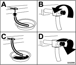
Draining the Fuel Tank
Note: The only recommended way to drain fuel from the tank is to use a syphon pump. A syphon pump can be purchased at a hardware store.
Danger
In certain conditions, gasoline is extremely flammable and highly explosive. A fire or explosion from gasoline can burn you and others and can damage property.
-
Drain gasoline from the fuel tank when the engine is cold. Do this outdoors in an open area. Wipe up any gasoline that spills.
-
Never smoke when draining gasoline, and stay away from an open flame, or where a spark may ignite the gasoline fumes.
-
Park the machine on a level surface, disengage the power takeoff (PTO), set the parking brake, turn the ignition key to the OFF position, and remove the key.
-
Clean around the fuel cap to prevent debris from getting into the fuel tank (Figure 51).
-
Remove the fuel cap.
-
Insert a syphon pump into the fuel tank.
-
Using the syphon pump, drain the fuel into a clean gas can (Figure 50).
-
Wipe up any spilled fuel.
Servicing the Fuel Filter
Replacing the Fuel Filter
| Maintenance Service Interval | Maintenance Procedure |
|---|---|
| Yearly |
|
Never install a dirty filter if it is removed from the fuel line.
Note: Wipe up any spilled fuel.
-
Disengage the PTO and set the parking brake.
-
Shut off the engine, remove the key, and wait for all moving parts to stop before leaving the operating position.
-
Close fuel-shutoff valve.
-
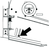
Squeeze the ends of the hose clamps together and slide them away from the filter (Figure 51).
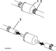
-
Remove the filter from the fuel lines.
-
Install a new filter and move the hose clamps close to the filter.
-
Open the fuel-shutoff valve.
-
Check for fuel leaks and repair if needed.
-
Wipe up any spilled fuel.
Electrical System Maintenance
Servicing the Battery
| Maintenance Service Interval | Maintenance Procedure |
|---|---|
| Every 100 hours |
|
Always keep the battery clean and fully charged. Use a paper towel to clean the battery case. If the battery terminals are corroded, clean them with a solution of four parts water and one part baking soda. Apply a light coating of grease to the battery terminals to prevent corrosion.
Voltage: 12 V
Warning
Battery posts, terminals, and related accessories contain lead and lead compounds, chemicals known to the State of California to cause cancer and reproductive harm. Wash hands after handling.
Danger
Battery electrolyte contains sulfuric acid which is a deadly poison and causes severe burns.
Do not drink electrolyte and avoid contact with skin, eyes or clothing. Wear safety glasses to shield your eyes and rubber gloves to protect your hands.
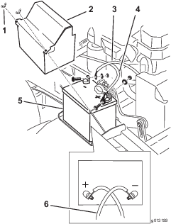
Removing the Battery
Warning
Battery terminals or metal tools could short against metal machine components causing sparks. Sparks can cause the battery gasses to explode, resulting in personal injury.
-
When removing or installing the battery, do not allow the battery terminals to touch any metal parts of the machine.
-
Do not allow metal tools to short between the battery terminals and metal parts of the machine.
Warning
Incorrect battery cable routing could damage the machine and cables causing sparks. Sparks can cause the battery gasses to explode, resulting in personal injury.
-
Always disconnect the negative (black) battery cable before disconnecting the positive (red) cable.
-
Always connect the positive (red) battery cable before reconnecting the negative (black) cable.
-
Disengage the PTO and set the parking brake.
-
Shut off the engine, remove the key, and wait for all moving parts to stop before leaving the operating position.
-
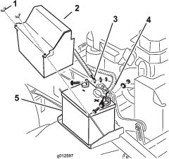
Disconnect the negative battery cable from the negative (-) battery terminal (Figure 52).
-
Slide the red terminal boot off the positive (red) battery terminal.
-
Remove the positive (red) battery cable (Figure 52).
-
Remove the battery hold-down plate and remove the battery (Figure 52).
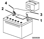
Installing the Battery
-
Place the battery onto the machine (Figure 52).
-
Secure the battery with the hold-down plate, the J-bolts, and the locknuts.
-
Install the positive (red) battery cable to positive (+) battery terminal with a nut, a washer, and a bolt (Figure 52).
-
Slide the rubber cover over the post.
-
Install the negative battery cable and ground wire to the negative (-) battery terminal with a nut, a washer, and a bolt (Figure 52).
Note: The battery cables cross over each other when they are correctly installed (Figure 52).
Charging the Battery
Warning
Charging the battery produces gasses that can explode.
Never smoke near the battery and keep sparks and flames away from battery.
Important: Always keep the battery fully charged (1.265 specific gravity) to prevent battery damage when the temperature is below 0°C (32°F).
-
Remove the battery from the chassis; refer to Removing the Battery.
-
Check the electrolyte level.
-
Ensure that the filler caps are installed on the battery.
-
Charge the battery for 1 hour at 25 to 30 A or 6 hours at 4 to 6 A.
-
When the battery is fully charged, unplug the charger from the electrical outlet, and disconnect the charger leads from the battery posts (Figure 53).
-
Install the battery onto the machine and connect the battery cables; refer to Installing the Battery.
Note: Do not run the machine with the battery disconnected; electrical damage may occur.
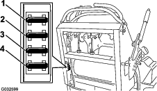
Servicing the Fuses
The electrical system is protected by fuses. It requires no maintenance. If a fuse blows, check the component or circuit for a malfunction or short.
-
Release the operator cushion from the rear of the machine.
-
Pull out on the fuse to remove and replace it (Figure 54).
-
Install the operator cushion.
Drive System Maintenance
Adjusting the Tracking
Note: Determine the left and right sides of the machine from the normal operating position.
-
Push both control levers forward the same distance.
-
Check if the machine pulls to one side.
Note: If it does, stop the machine and set the parking brake.
-
Release the cushion from the rear of the machine.
-
Rotate the right cable adjustment to position the right motion-control lever in the center of the control-panel neutral-lock slot (Figure 56).
-
Rotate the left cable adjustment to match the left wheel speed to the previously set right wheel speed.
-
Adjust in quarter-turn increments until the machine tracks straight.
Note: Only adjust the left cable to match the left wheel speed to the right wheel speed. Do not adjust the right wheel speed as this positions the right motion-control lever out of the center for the control-panel neutral-lock slot.
-
Check for proper tracking.
Note: If the machine does not start after adjusting the tracking, make sure that the proximity switch target aligns with the bolt attached to the motion-control lever; refer to Adjusting the Proximity Switch.
-
Repeat the cable adjustment until the tracking is correct.
-
Check that the machine does not creep from neutral with the park brakes disengaged.
Important: Do not rotate the linkage too far, as this may cause the machine to creep in neutral.
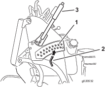
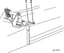
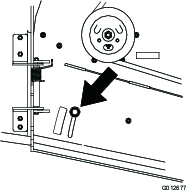
Adjusting the Proximity Switch
Use this procedure if the machine does not start after adjusting the tracking.
-
Ensure that the bolt attached to the motion-control lever aligns with the proximity-switch target (Figure 57).
-
If needed, loosen the bolts and adjust the proximity switch until the target aligns with the bolt attached to the motion-control lever (Figure 57).
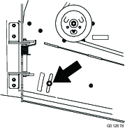
-
Check the distance of the bolt to the proximity switch; it needs to be between 0.51 to 1.02 mm (0.02 to 0.04 inches) as shown in Figure 57.
-
If adjustment is needed, loosen the jam nut and adjust the bolt to the correct distance.
-
Tighten the jam nut after adjusting the bolt (Figure 57).
-
Test the safety-interlock system before operation.

Checking the Tire Pressure
| Maintenance Service Interval | Maintenance Procedure |
|---|---|
| Every 50 hours |
|
Maintain the air pressure in the rear tires at 83 to 97 kPa (12 to 14 psi).
Important: Uneven tire pressure can cause an uneven cut.
Note: The front tires are semi-pneumatic tires and do not require air-pressure maintenance.
Adjusting the Caster-Pivot Bearing
| Maintenance Service Interval | Maintenance Procedure |
|---|---|
| Every 500 hours |
|
-
Disengage the blade-control switch (PTO), move the motion-control levers to the NEUTRAL-LOCK position, and set the parking brake.
-
Shut off the engine, remove the key, and wait for all moving parts to stop before leaving the operating position.
-
Remove the dust cap from the caster and tighten the locknut (Figure 59).
-
Tighten the locknut until the spring washers are flat, and then back off a 1/4 turn to properly set the preload on the bearings (Figure 59).
Important: Make sure that the spring washers are installed correctly as shown in Figure 59.
-
Install the dust cap (Figure 59).
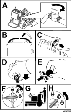
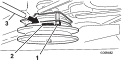
Adjusting the Electric Clutch
| Maintenance Service Interval | Maintenance Procedure |
|---|---|
| Every 100 hours |
|
The clutch is adjustable to ensure proper engagement and proper braking.
-
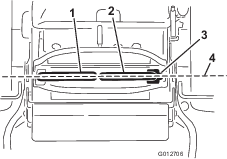
Insert a 0.4 to 0.5 mm (0.01 to 0.02 inch) feeler gauge through an inspection slot in the side of the assembly.
Note: Make sure that it is between the armature and the rotor friction surfaces.
Note: The gap needs to be at least 0.4 mm (0.02 inches) and not more than 0.5 mm (0.02 inches).
-
If adjustment is needed, use a 0.4 mm (0.02 inches) feeler gauge to set each of the 3 adjustment-slot positions.
-
Tighten the lock nuts until there is slight binding on the feeler gauge but it can be moved easily within the air gap (Figure 60).
-
Repeat this for the remaining slots.
-
Check each slot again and make slight adjustments until the feeler gauge is between the rotor and armature with very slight contact between them.
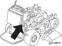
Cooling System Maintenance
Cleaning the Air-Intake Screen
| Maintenance Service Interval | Maintenance Procedure |
|---|---|
| Before each use or daily |
|
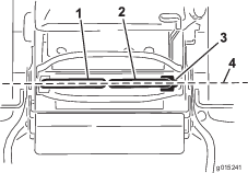
Before each use, remove any buildup of grass, dirt, or other debris from the cylinder and cylinder-head cooling fins, air-intake screen on the flywheel end, and the carburetor-governor levers and linkage. This helps ensure that adequate cooling and correct engine speed, and reduces the possibility of overheating or mechanical damage to the engine.
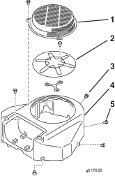
Cleaning the Cooling System
| Maintenance Service Interval | Maintenance Procedure |
|---|---|
| Every 100 hours |
|
-
Disengage the PTO and set the parking brake.
-
Shut off the engine, remove the key, and wait for all moving parts to stop before leaving the operating position.
-
Remove the air-intake screen and the fan housing (Figure 61).
-
Clean the debris and grass from the engine parts.
-
Install the air-intake screen and fan housing (Figure 61).
Brake Maintenance
Servicing the Brake
Before each use, check the brakes on both a level surface and slope.
Always set the parking brake when you stop the machine or leave it unattended. If the parking brake does not hold securely, adjust it.
Checking the Parking Brake
| Maintenance Service Interval | Maintenance Procedure |
|---|---|
| Before each use or daily |
|
Important: Ensure that the mower is on a level surface when checking and adjusting the brake.
-
Park the machine on a level surface and disengage the PTO.
-
Shut off the engine, remove the key, and wait for all moving parts to stop before leaving the operating position.
-
Release the parking brake; refer to Releasing the Parking Brake.
-
Check the tire pressure; refer to Checking the Tire Pressure.
-
With the brake released, measure the distance between the brake bar and the tire on each side.
-
Using the side with the smallest clearance, ensure that the distance is between 3 and 6 mm (1/8 and 1/4 inches) as shown in Figure 62); refer to Adjusting the Brakes when adjustment is needed.
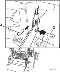
Adjusting the Brakes
If the gap between the brake bar and tire is not correct, adjust the brake.
-
Park the machine on a level surface and disengage the PTO, and set the parking brake.
-
Shut off the engine, remove the key, and wait for all moving parts to stop before leaving the operating position.
-
Release the parking brake; refer to Releasing the Parking Brake.
-
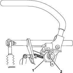
To adjust the brake, remove the clevis pin and hairpin cotter from the lower-brake lever and yoke (Figure 63).
-
Adjust the yoke (Figure 62).
Note: The distance between the brake bar and the tire needs be between 3 and 6 mm (1/8 and 1/4 inches).
Note: To tighten the brake, rotate the yoke up. To loosen the brake, rotate the yoke down.
-
Check the brake operation again; refer to Checking the Parking Brake.
-
Secure the yoke to the lower-brake lever with the clevis pin and hairpin cotter (Figure 63).
Belt Maintenance
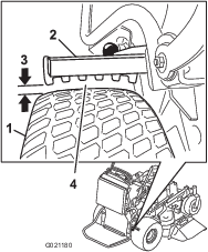
Checking the Belts
| Maintenance Service Interval | Maintenance Procedure |
|---|---|
| Every 100 hours |
|
Check belts for cracks, frayed edges, burn marks, wear, signs of overheating or any other damage.
The signs of a worn mower belt are squealing while the belt is rotating, blades slipping while you are cutting grass, frayed belt edges, burn marks, and cracks. Replace the mower belt if you detect any of these signs.
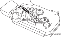
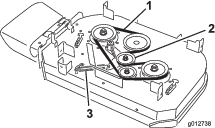
Replacing the Mower-Deck Belt
For Models with a 91 cm Deck
Important: The fasteners on the covers of this machine are designed to remain on the cover after removal. Loosen all of the fasteners on each cover a few turns so that the cover is loose but still attached, then go back and loosen them until the cover comes free. This prevents you from accidentally stripping the bolts free of the retainers.
-
Disengage the PTO and set the parking brake.
-
Shut off the engine, remove the key, and wait for all moving parts to stop before leaving the operating position.
-
Loosen the bolts and remove the right belt cover with the bolt attached to it.
-
Remove the spring from the anchor post on the idler-pulley arm (Figure 64).
-
Remove the worn mower belt (Figure 64).
-
Install the new mower belt around the clutch pulley, the deck pulleys, and the idler pulley (Figure 64).
-
Install the spring onto the anchor post on the idler-pulley arm (Figure 64).
-
Install the belt cover onto the mower deck and secure the bolt.
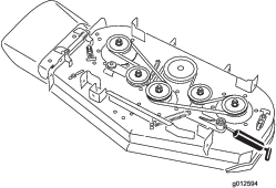
Replacing the Mower-Deck Belts
For Models with a 102 cm Deck
Important: The fasteners on the covers of this machine are designed to remain on the cover after removal. Loosen all of the fasteners on each cover a few turns so that the cover is loose but still attached, then go back and loosen them until the cover comes free. This prevents you from accidentally stripping the bolts free of the retainers.
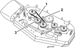
Replacing the Right Mower-Deck Belt
-
Disengage the PTO and set the parking brake.
-
Shut off the engine, remove the key, and wait for all moving parts to stop before leaving the operating position.
-
Loosen the bolts and remove the belt covers with the bolts attached to them.
-
Remove the spring from the anchor post on the idler-pulley arm (Figure 65).
-
Remove the worn mower belt (Figure 65).
-
Install the new mower belt around the deck pulleys and idler pulley (Figure 65).
-
Install the spring onto the anchor post on the idler-pulley arm (Figure 65).
-
Install the belt covers onto the mower deck and secure the bolts.
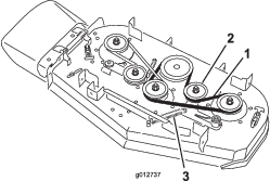
Replacing the Left Mower-Deck Belt
-
Disengage the PTO and set the parking brake.
-
Shut off the engine, remove the key, and wait for all moving parts to stop before leaving the operating position.
-
Loosen the bolts and remove the belt covers with the bolts attached to them.
-
To remove the left mower belt, the right mower belt needs to be removed first; refer to Replacing the Right Mower-Deck Belt.
-
Remove the spring from the anchor post on the idler-pulley arm (Figure 66).
-
Remove the worn mower belt (Figure 66).
-
Install the new mower belt around the deck pulleys, the clutch pulley, and the idler pulley (Figure 66).
-
Install the spring onto the anchor post (Figure 66).
-
Install the right mower belt; refer to Replacing the Right Mower-Deck Belt.
-
Install the belt covers onto the mower deck and secure the bolts.
Replacing the Pump-Drive Belt
| Maintenance Service Interval | Maintenance Procedure |
|---|---|
| Every 100 hours |
|
-
Disengage the PTO and set the parking brake.
-
Shut off the engine, remove the key, and wait for all moving parts to stop before leaving the operating position.
-
Remove the mower-deck belt.
-
Tilt the machine; refer to Raising the Mower for Access.
-
Remove the shoulder bolt, the nut, and the washer from the engine deck and connected spring (Figure 67).
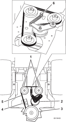
-
Remove the pump-drive belt (Figure 67).
-
Install the new belt around the clutch and the 2 pump pulleys.
-
Install the spring onto the shoulder bolt and washer, and connect it to the engine deck with the nut (Figure 67).
-
Lower the machine to the operating position.
-
Install the mower-deck belt.
Controls System Maintenance
Adjusting the Motion-Control Handle Positions
Adjusting the Right Motion-Control Lever
If the motion-control levers do not align horizontally, adjust the right motion-control lever.
Note: Adjust the horizontal alignment before the front to back alignment.
-
Disengage the PTO, move the right motion-control lever to the NEUTRAL position, and set the parking brake.
-
Shut off the engine, remove the key, and wait for all moving parts to stop before leaving the operating position.
-
Push the right motion-control lever down out of the NEUTRAL-LOCK position (Figure 68).
-
Check if the right motion-control lever aligns horizontally with the left motion-control lever (Figure 68).
Note: To adjust the right motion-control lever horizontally, adjust the cam.
-
Release the cushion from the rear of the machine.
-
Loosen the nut holding the cam (Figure 69).
-
Adjust the cam until it aligns with the left motion-control lever and tighten the nut for the cam.
Note: Moving the cam clockwise (in the vertical position) lowers the handle, while moving it counterclockwise (in the vertical position) raises the handle.
Important: Ensure that the flat portion of the cam does not go above a vertical position (right or left), or you may cause damage to the switch.
Adjusting the Neutral Position for the Motion-Control Levers
Important: Ensure that the tracking of the mower is correct after adjusting the motion-control levers. Adjusting the tracking and aligning the motion-control levers front to back is the same procedure (Figure 70).
Note: Adjust the horizontal alignment before the front to back alignment.
If the motion-control levers do not align front to back, or the right side control lever does not move easily into the NEUTRAL-LOCK position, adjustment is required.
-
After you finish the horizontal alignment, check the front-to-back alignment by slightly pushing the motion-control levers forward to take up any slack in the linkage for the control levers (Figure 70).
-
Ensure that the right motion-control lever moves easily into the NEUTRAL-LOCK position.
Note: Turn the cable adjustment clockwise to move the motion-control handle forward. Turn the cable adjustment counterclockwise to move the motion-control handle rearward.
-
Rotate the cable adjustment on the right side when adjustment is needed.
Note: Adjust the cable adjustment in quarter-turn increments.
-
After the right motion-control lever moves easily into the NEUTRAL-LOCK position, adjust the left motion-control lever to align it with the right motion-control lever.
-
Check for proper tracking; refer to Adjusting the Tracking .
-
Install the cable lock onto the cable-adjusting nuts to secure the adjustment (Figure 71).
Hydraulic System Maintenance
Servicing the Hydraulic System
Hydraulic Fluid Type: Toro® HYPR-OIL™ 500 hydraulic fluid or Mobil® 1 15W-50 synthetic motor oil.
Hydraulic System Fluid Capacity: 2.0 L (67 oz)
Important: Use the specified oil or equivalent. Other fluids could cause system damage.
Checking the Hydraulic Fluid
| Maintenance Service Interval | Maintenance Procedure |
|---|---|
| After the first 8 hours |
|
| Every 50 hours |
|
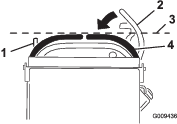
Note: The baffle inside the tank has 2 levels depending if the oil is warm or cold.
-
Position the machine on a level surface.
-
Disengage the power takeoff (PTO) and shut off the engine.
-
Wait for all moving parts to stop before leaving the operating position and set the parking brake.
-
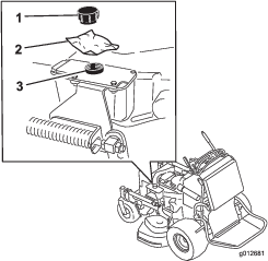
Clean the area around the cap and the filler neck of the hydraulic tank (Figure 72).
-
Remove the cap from the filler neck (Figure 72).
Note: Look inside to check the fluid level in the reservoir.
-
Add fluid to the reservoir until it reaches the cold level of the baffle.
-
Run the machine at low idle for 15 minutes to allow any air to purge out of the system and warm the fluid; refer to Starting and Stopping the Engine.
-
Check the fluid level while the fluid is warm.
Note: If required, add fluid to the reservoir until it is between the hot level and the cold level.
Note: The fluid level should be below the hot level of the baffle when the fluid is warm (Figure 72).
-
Install the cap on the filler neck.
Warning
Hydraulic fluid escaping under pressure can penetrate skin and cause injury.
-
If hydraulic fluid is injected into the skin, it must be surgically removed within a few hours by a doctor familiar with this type of injury. Gangrene may result if this is not done.
-
Keep your body and hands away from pinhole leaks or nozzles that eject high-pressure hydraulic fluid.
-
Use cardboard or paper to find hydraulic leaks.
-
Safely relieve all pressure in the hydraulic system before performing any work on the hydraulic system.
-
Make sure that all hydraulic-fluid hoses are in good condition, and all that the hydraulic connections and fittings are tight before applying pressure to hydraulic system.
-
Replacing the Hydraulic Fluid
| Maintenance Service Interval | Maintenance Procedure |
|---|---|
| Every 250 hours |
|
| Every 500 hours |
|
Warning
Hot hydraulic fluid can cause severe burns.
Allow the hydraulic fluid to cool before performing any maintenance to the hydraulic system.
-
Disengage the PTO and set the parking brake.
-
Shut off the engine and wait for all moving parts to stop before leaving the operating position.
-
Remove hydraulic reservoir cap.
-
Locate the front hydraulic hose under the hydraulic tank and place a drain pan under the tank (Figure 73).
-
Loosen the hose clamp and move it down the hose.
-
Remove the front hydraulic hose and allow the fluid to run out of the tank.
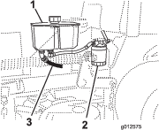
-
Change the hydraulic filter; refer to Replacing the Hydraulic Filter.
-
Connect the hydraulic hose under the tank.
-
Add fluid to the tank until it reaches the cold baffle of the tank.
Important: Use the specified oil or equivalent. Other fluids could cause system damage.
-
Install the hydraulic-tank cap.
-
Start engine and let run for about 2 minutes to purge air from the system.
-
Shut off the engine and check for leaks.
Note: If one or both wheels do not drive, refer to Bleeding the Hydraulic System.
-
Check the level of the fluid and add fluid, if required.
Important: Do not overfill.
Replacing the Hydraulic Filter
| Maintenance Service Interval | Maintenance Procedure |
|---|---|
| After the first 8 hours |
|
| Every 500 hours |
|
Warning
Hot hydraulic fluid can cause severe burns.
Allow the hydraulic fluid to cool before performing any maintenance to the hydraulic system.
-
Disengage the PTO and set the parking brake.
-
Shut off the engine and wait for all moving parts to stop before leaving the operating position.
Important: Do not substitute automotive oil filter, or severe hydraulic system damage may result.
-
Locate the filter and place a drain pan under the filter (Figure 74).
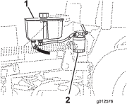
-
Remove the old filter and wipe the filter-adapter gasket surface clean (Figure 75).
-
Apply a thin coat of hydraulic fluid to the rubber gasket on the replacement filter.
-
Install replacement hydraulic filter onto the filter adapter.
-
Turn the oil filter clockwise until the rubber gasket contacts the filter adapter and tighten the filter an additional 1/2 turn (Figure 75).
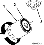
-
Clean up any spilled fluid.
-
Check the fluid in the reservoir and add fluid to the tank until it reaches the cold baffle of the tank.
Important: Use the specified oil or equivalent. Other fluids could cause system damage.
-
Start the engine and let it run for about 2 minutes to purge air from the system.
-
Shut off the engine and check for leaks.
Note: If one or both wheels do not drive, refer to Bleeding the Hydraulic System.
-
Check the fluid level and add fluid, if required.
Important: Do not overfill.
Bleeding the Hydraulic System
The traction system is self-bleeding, however, it may be necessary to bleed the system if fluid is changed or after work is performed on the system.
-
Disengage the PTO and set the parking brake.
-
Shut off the engine and wait for all moving parts to stop before leaving the operating position.
-
Raise the rear of the machine onto jack stands high enough to raise the drive wheels off the ground.
-
Start the engine and move the throttle control to the idle position.
Note: If the drive wheel does not rotate, it is possible to assist the purging of the system by carefully rotating the tire in the forward direction.
-
Check the hydraulic fluid level as it drops, and add fluid as required to maintain the proper level.
-
Repeat this procedure for the opposite wheel.
Checking the Hydraulic Hoses
| Maintenance Service Interval | Maintenance Procedure |
|---|---|
| Every 100 hours |
|
Check the hydraulic hoses for leaks, loose fittings, kinks, loose mounting supports, wear, general weathering, and chemical deterioration. Make any necessary repairs before operating.
Note: Keep areas around the hydraulic system clean from grass and debris buildup.
Note: Extended operating time at high temperatures in a hot climate may lead to deterioration of hoses and seals. Inspect more frequently in a hot climate, and change the hydraulic fluid and filter more frequently.
Mower Deck Maintenance
Servicing the Cutting Blades
To ensure a superior quality of cut, keep the blades sharp. For convenient sharpening and replacement, you may want to keep extra blades on hand.
Warning
A worn or damaged blade can break, and a piece of the blade could be thrown at you or bystanders, resulting in serious personal injury or death.
-
Inspect the blades periodically for wear or damage.
-
Replace a worn or damaged blade.
Before Inspecting or Servicing the Blades
Park the machine on a level surface, disengage the blades and set the parking brake. Turn the ignition key to OFF. Remove the key, and disconnect the spark plug wires from the spark plugs.
Inspecting the Blades
| Maintenance Service Interval | Maintenance Procedure |
|---|---|
| Before each use or daily |
|
-
Inspect the cutting edges (Figure 76).
-
If the edges are not sharp or have nicks, remove and sharpen the blade; refer to Sharpening the Blades.
-
Inspect the blades, especially in the curved area.
-
If you notice any cracks, wear, or a slot forming in this area, immediately install a new blade (Figure 76).
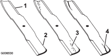
Checking for Bent Blades
-
Disengage the PTO, move the motion-control levers to the NEUTRAL-LOCK position, and set the parking brake.
-
Shut off the engine, remove the key, and wait for all moving parts to stop before leaving the operating position.
-
Rotate the blades until the ends face forward and backward.
-
Measure from a level surface to the cutting edge, position A, of the blades (Figure 77).
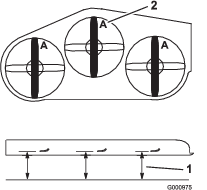
-
Rotate the opposite ends of the blades forward.
-
Measure from a level surface to the cutting edge of the blades at the same position as in step 4 above.
Note: The difference between the dimensions obtained in steps 4 and 5 must not exceed 3 mm (1/8 inch).
Note: If this dimension exceeds 3 mm (1/8 inch), replace the blade.
Warning
A blade that is bent or damaged could break apart and could critically injure you or bystanders.
-
Always replace a bent or damaged blade with a new blade.
-
Do not file or create sharp notches in the edges or surfaces of the blade.
-
Removing the Blades
Replace the blades if they hit a solid object, if a blade is out of balance, or if a blade is bent. To ensure optimum performance and continued safety conformance of the machine, use genuine Toro replacement blades. Replacement blades made by other manufacturers may result in nonconformance with safety standards.
-
Hold the blade end using a rag or a thickly padded glove.
-
Remove the blade bolt, the curved washer, and the blade from the spindle shaft (Figure 78).
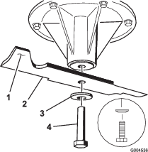
Sharpening the Blades
-
Use a file to sharpen the cutting edge at both ends of the blade (Figure 79).
Note: Maintain the original angle.
Note: The blade retains balance if the same amount of material is removed from both cutting edges.
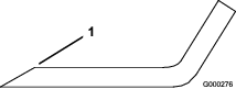
-
Check the balance of the blade by putting it on a blade balancer (Figure 80).
Note: If the blade stays in a horizontal position, the blade is balanced.

-
If the blade is not balanced, file some metal off the end of the sail area only (Figure 78).
-
Repeat this procedure until the blade is balanced.
Installing the Blades
-
Install the blade onto the spindle shaft (Figure 81).
Important: The curved part of the blade must be pointing upward toward the inside of the mower to ensure proper cutting.
-
Install the spring disk and blade bolt (Figure 81).
Note: The spring-disk cone must be installed toward the bolt head (Figure 81).
-
Torque the blade bolt to 115 to 150 N∙m (85 to 110 ft-lb).
Leveling the Mower Deck
Preparing the Machine
-
Position the machine on a flat surface.
-
Disengage the PTO, move the motion-control levers to the NEUTRAL-LOCK position, and set the parking brake.
-
Shut off the engine, remove the key, and wait for all moving parts to stop before leaving the operating position.
-
Check the tire pressure of both drive tires; refer to Checking the Tire Pressure.
-
Lower the mower deck to the 76 mm (3 inch) height-of-cut position.
Note: The actual cutting height will not be adjusted until the deck has been leveled; refer to Matching the Height of Cut.
-
Check the distance between the swivels, measuring at the center of the swivels (center-to-center length) on each threaded rod (Figure 82).
Note: Ensure that the length is 49.5 cm (19-1/2 inches) for 91 cm (36 inch) mower decks and 43.7 cm (17-3/16 inches) for 102 cm (40 inch) mower decks.
-
Loosen the jam nuts at the front swivel.
-
Using the jam nuts, adjust the length of the threaded rod to achieve the correct distance.
-
Tighten the jam nuts at the front swivel.
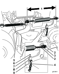
-
Check the distance between the yoke and the deck hanger arm at each yoke.
Note: This distance needs to be 11 mm (7/16 inch) as shown in Figure 83.
-
If adjustment is needed, loosen the upper chain bolt (Figure 82).
-
Loosen the jam nut and adjust the adjustment bolt to achieve the correct distance as shown in Figure 83.
-
Tighten the jam nut and the upper chain bolt.
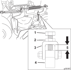
Adjusting the Right Side Front-to-Rear Mower Deck Pitch
-
Position the right blade front-to-rear (Figure 84).
-
Measure the right blade at the C location, from a level surface to the cutting edge of the blade tip, and record this measurement (Figure 84).
-
Measure the right blade at the D location, from a level surface to the cutting edge of the blade tip, and record this measurement (Figure 84).
Note: The mower blade should be a 6 to 10 mm (1/4 to 3/8 inch) lower at position C than at position D (Figure 84). If it is not correct, proceed to the following steps.
-
Loosen the jam nuts at the right and left front swivels.
-
Using the right jam nuts, adjust the length of the right threaded rod to achieve the 6 to 10 mm (1/4 to 3/8 inch) front-to-rear pitch.
-
Tighten the jam nuts at the right and left front swivels.
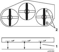
Matching the Rear of the Mower Deck
-
Position the left and right blades front-to-rear.
-
Measure the left blade at the B location, from a level surface to the cutting edge of the blade tip, and record this measurement (Figure 85).
-
Measure the right blade at the D location, from a level surface to the cutting edge of the blade tip, and record this measurement (Figure 85).
Note: The measurement at position B needs to be within 3 mm (1/8 inch) of the measurement at position D. (Figure 85). If it is not correct, proceed to the following steps.
-
Loosen the jam nuts at the left front swivel.
-
Using the left jam nuts, adjust the length of the left hand threaded rod until location B matches location D.
-
Tighten the jam nuts at the left front swivel.
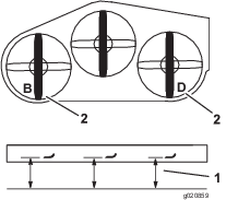
Leveling the Front of the Mower Deck
-
Position the left and right blades front-to-rear.
-
Inspect the front chains and ensure that each chain has tension.
Note: If either chain is loose, adjust the threaded rod with the loose chain to achieve tension on that chain.
-
Measure the left blade at the A location, from a level surface to the cutting edge of the blade tip, and record this measurement (Figure 86).
-
Measure the right blade at the C location, from a level surface to the cutting edge of the blade tip, and record this measurement (Figure 86).
Note: The measurement between location A and C needs to be within 3 mm (1/8 inch). If it is not correct, proceed to the following steps.
-
Loosen the upper chain bolts (Figure 82).
-
Loosen the jam nuts on each yoke.
-
Adjust the adjustment bolts in the yokes, at locations A and C, to achieve the correct height.
-
Tighten the jam nuts and upper chain bolts.
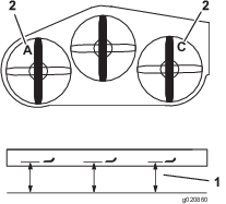
Matching the Height of Cut
-
Lower the mower to the 76 mm (3 inches) height-of-cut position.
-
Position the right blade front-to-rear.
-
Measure the right blade at location C, from a level surface to the cutting edge of the blade tip, and record this measurement (Figure 86).
Note: The measurement at location C needs to be within an 3 mm (1/8 inch) of the 76 mm (3 inches) height-of-cut setting. If it is not correct, proceed to the following steps.
-
Loosen the jam nuts at both ends of the turnbuckle (Figure 87).
Note: The end of the turnbuckle with the groove machined in it has left threads (Figure 87).
-
Adjust the turnbuckle to raise or lower the deck height to achieve 76 mm (3 inches) at location C.
-
Tighten the jam nuts at both ends of the turnbuckle.
-
Check and ensure that the mower-deck lift lever latches into the transport position.
Note: If it does not latch into the transport position, adjust the turn buckle until it latches into the transport position.
-
Tighten the jam nuts.
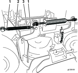
Adjusting the Compression Spring
Note: Adjusting the compression spring alters how much the deck floats and how much effort it takes to lift the deck when using the height-of-cut handle.
-
More spring compression reduces the handle lift force required and causes the deck to float more.
-
Less spring compression increases the handle lift force required and causes the deck to float less.
-
Raise the deck-lift lever and lock it into the transport position.
-
Check the length of the compression spring.
Note: Nominal length is 28.2 cm (11-1/8 inches) for 91 cm (36 inch) mower decks and 25.7 cm (10-1/8 inches) for 102 cm (40 inch) mower decks (Figure 88).
-
Adjust this distance, by loosening the spring-jam nut and turning the nut in front of each spring (Figure 88).
-
Lock the nut into position by tightening the spring-jam nut (Figure 88).
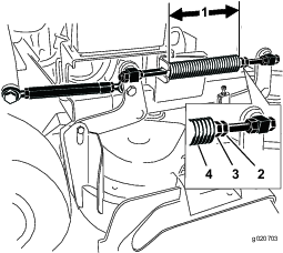
Replacing the Grass Deflector
Warning
An uncovered discharge opening could allow the machine to throw objects in the operator's or bystander's direction and result in serious injury. Also, contact with the blade could occur.
Do not operate the machine unless you install a cover plate, a mulch plate, grass deflector, or bagger.
-
Remove the locknut, bolt, spring, and spacer holding the deflector to the pivot brackets (Figure 89).
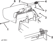
-
Remove the damaged or worn grass deflector.
-
Place the spacer and the spring onto the grass deflector.
-
Place 1 J-hook end of the spring behind the deck edge.
Note: Make sure that 1 J-hook end of spring is installed behind deck edge before installing the bolt as shown in Figure 89.
-
Install the bolt and the nut.
-
Place 1 J-hook end of the spring around the grass deflector (Figure 89).
Important: The grass deflector must be able to rotate. Lift the deflector up to the full open position, and ensure that it rotates into the full down position.
Cleaning
Cleaning under the Mower
| Maintenance Service Interval | Maintenance Procedure |
|---|---|
| Before each use or daily |
|
Remove the grass buildup under the mower daily.
-
Disengage the PTO, move the motion-control levers to the NEUTRAL-LOCK position and set the parking brake.
-
Shut off the engine, remove the key, and wait for all moving parts to stop before leaving the operating position.
-
Raise the front of the machine and use jack stands to support the mower.
Disposing of Waste
Engine oil, batteries, hydraulic fluid, and engine coolant are pollutants to the environment. Dispose of these according to your state and local regulations.
Storage
Cleaning and Storage
-
Disengage the power takeoff (PTO), set the parking brake, turn the ignition key to off, and remove the key.
-
Remove grass clippings, dirt, and grime from the external parts of the entire machine, especially the engine.
Important: You can wash the machine with a mild detergent and water. Do not pressure wash the machine. Avoid excessive use of water, especially near the drive system and engine. Pressure washing can force dirt and water into critical parts, such as spindle bearings and electrical switches.
-
Check the brake; refer to Servicing the Brake.
-
Service the air cleaner; refer to Servicing the Air Cleaner.
-
Grease the machine; refer to Lubrication.
-
Change the engine oil; refer to Changing the Engine Oil.
-
Check the tire pressure; refer to Checking the Tire Pressure.
-
For long-term storage:
-
Add stabilizer/conditioner additive to fuel in the tank.
-
Run engine to distribute conditioned fuel through the fuel system (5 minutes).
-
Stop engine, allow to cool and drain the fuel tank; refer to Draining the Fuel Tank, or operate engine until it stops.
-
Restart engine and run until it stops. Repeat, on Choke until engine will not restart.
-
Dispose of fuel properly. Recycle as per local codes.
Note: Do not store gasoline with stabilizer/conditioner over 90 days.
-
-
Remove the spark plug(s) and check its condition; refer to Servicing the Spark Plug. With the spark plug(s) removed from the engine, pour two tablespoons of engine oil into the spark plug hole. Now use the starter to crank the engine and distribute the oil inside the cylinder. Install the spark plug(s). Do not install the wire on the spark plug(s).
-
Check and tighten all bolts, nuts, and screws. Repair or replace any part that is damaged or defective.
-
Paint all scratched or bare metal surfaces. Paint is available from your Authorized Service Dealer.
-
Store the machine in a clean, dry garage or storage area. Remove the key from the ignition switch and keep it in a memorable place. Cover the machine to protect it and keep it clean.
Troubleshooting
| Problem | Possible Cause | Corrective Action |
|---|---|---|
| The engine does not start, starts hard, or fails to keep running. |
|
|
| The engine loses power. |
|
|
| The engine overheats. |
|
|
| The machine does not drive. |
|
|
| There is abnormal vibration. |
|
|
| The cutting height is uneven. |
|
|
| The blades do not rotate. |
|
|
Schematics
Hydraulic Schematic
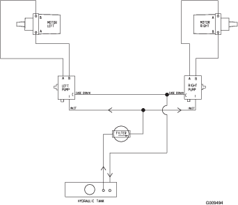
Electrical Schematic