CALIFORNIA
Proposition 65 Warning
 |
Safety decals and instructions are easily visible to the operator and are located near any area of potential danger. Replace any decal that is damaged or missing. |
Park the machine on a level surface.
Lower the cutting units.
Engage the parking brake.
Shut off the engine and remove the key.
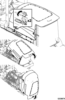
If there are lights on the roll bar, remove the lights and the mounting hardware from the roll bar.
Retain the lights and the mounting hardware.
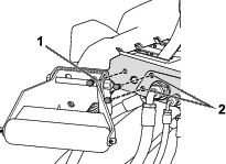
Remove the locking pins from both sides of the roll bar (Figure 1).
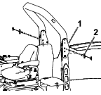
Remove the bolts from both sides of the foot frame (Figure 2) as shown in Figure 3 and Figure 4.
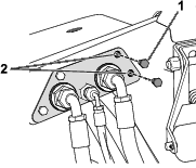
Use a drill (3/8 inch) to increase the diameter of the 2 holes on both sides of the foot frame as shown in Figure 3 and Figure 4.
Parts needed for this procedure:
| Left front mount | 1 |
| Right front mount | 1 |
| Right brace | 1 |
| Left brace | 1 |
| Carriage bolt (5/16 x 3/4 inch) | 56 |
| Flange nut (5/16 inch) | 60 |
| Flange nut (3/8 inch) | 6 |
| Bolt (3/8 x 1 inch) | 4 |
| Lower bracket mount | 1 |
| Hex-head flange bolt (5/16 x 1 inch) | 4 |
| Front roof mount | 1 |
| Left upper bracket | 1 |
| Right upper bracket | 1 |
| Rear roof mount | 1 |
| Left side mount | 1 |
| Right side mount | 1 |
| Channel mount | 4 |
| Right roof mount | 1 |
| Left roof mount | 1 |
| Lower window seal | 1 |
| Bolt (3/8 x 3/4 inch) | 2 |
| Plastic rivet | 14 |
| Plastic plug | 2 |
| Panel plug | 2 |
| Push rivet | 8 |
| Side channel mount | 2 |
| Roof channel mount | 2 |
| Bolt (3/4 x 4 inches) | 2 |
| Washer | 4 |
| Locknut (3/4 inch) | 2 |
| Carriage bolt (1/4 x 3/4 inch) | 4 |
| Flange nut (1/4 inch) | 4 |
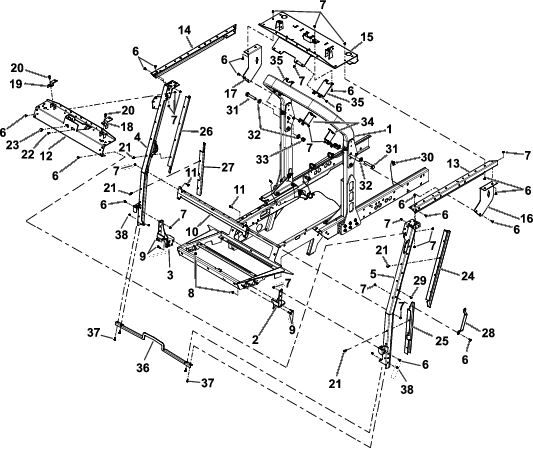
Refer to Figure 5 as you perform the following steps.
Install 2 bolts (3/4 x 4 inches), 4 washers, and 2 locknuts (3/4 inch) to the left and right pivot plates on the roll bar.
Install the left and right front mount bases onto the floor panel using 4 bolts (3/8 x 1 inch) and 4 flange nuts (3/8 inch).
Install the rear roof mount onto the upper part of the roll bar with 2 roof channel mounts, 8 carriage bolts (5/16 x 3/4 inch), and 8 flange nuts (5/16 inch).
Note: Ensure that the mount is centered on the roll bar.
Note: Tighten the bolts, then loosen them a half turn.
Install the left and right side mounts to the left and right upper brackets, respectively, with 4 carriage bolts (5/16 x 3/4 inch) and 4 flange nuts (5/16 inch).
Install the left and right side mounts to the roll bar with 2 side channel mounts, 8 carriage bolts (5/16 x 3/4 inch), and 8 flange nuts (5/16 inch).
Install the left and right braces onto the front mount bases with 6 carriage bolts (5/16 x 3/4 inch) and 6 flange nuts (5/16 inch).
Note: Tighten the bolts, then loosen them a half turn.
Install the left and right upper brackets onto the rear roof mount and braces with 16 carriage bolts (5/16 x 3/4 inch) and 16 flange nuts (5/16 inch).
Note: Tighten the bolts, then loosen them a half turn.
Install the 2 panel plugs and 2 plastic plugs to the front roof mount.
Install the left and right roof mounts to the front roof mount with 2 bolts (3/8 x 3/4 inch) and 2 flange nuts (3/8 inch).
Install the front roof mount with 12 carriage bolts (5/16 x 3/4 inch) and 12 flange nuts (5/16 inch).
If you are also installing the Operator Fan and Interior Roof Kit:
Keep all fasteners loose.
Mount the Operator Fan and Interior Roof Kit.
Tighten all fasteners.
Install the lower mount bracket to the left and right brace assemblies with 4 hex-head-flange bolts (5/16 x 1 inch) and 4 flange nuts (5/16 inch).
Secure all fasteners that were left loose.
Install 3 push rivets into the left brace and 5 push rivets into the right brace.
Install the grab handle to the left brace with 2 carriage bolts (5/16 x 3/4 inch) and 2 flange nuts (5/16 inch).
Install the lower window seal to the front mounts with 4 carriage bolts (1/4 x 3/4 inch) and 4 flange nuts (1/4 inch).
Install the upper left and lower left post covers onto the left brace with 7 plastic rivets.
Install the upper right and lower right post covers onto the right brace with 7 plastic rivets.
Parts needed for this procedure:
| Wire harness | 1 |
| Cable tie | 4 |
Unlatch and raise the battery box cover (Figure 6).
Open the hood (Figure 7).
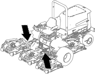
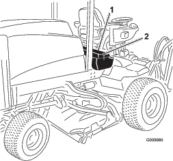
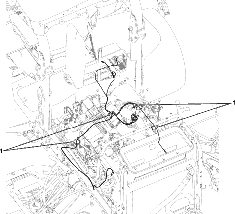
Route the wire harness as shown in Figure 8.
Use the cable ties to secure the wire harness to machine; refer to Figure 8
Note: Route the wire harness through the bottom of the battery box and under the machine frame.
Close the hood and the battery box cover.
Note: Secure the battery box cover closed with the latch.
Parts needed for this procedure:
| Sunshade | 1 |
| Control panel | 1 |
| Hole plug | 4 |
| Plastic rivet | 12 |
| Clip | 4 |
| Sealing washer | 4 |
| Hex-head-flange bolt (1/4 x 1 inch) | 4 |
| Serial plate | 1 |
| Pop rivet | 2 |
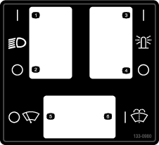
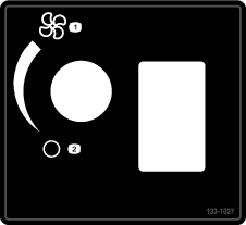
Install the 4 hole plugs to the control panel (Figure 9).
Note: If you are installing other accessories in the control panel holes, do not install the hole plugs.
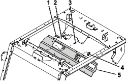
Use 2 pop rivets to secure the serial plate to the control panel (Figure 9).
Note: Install the serial plate so that it can be read by the operator.
Align the mounting holes on the control panel with the holes in the front roof mount (Figure 9).
Secure the front panel onto the front roof mount by inserting 12 plastic rivets into their respective holes and pushing the plunger on each plastic rivet until it is secure (Figure 9).
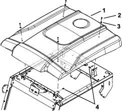
Install the sunshade onto the frame with 4 hex-head flange bolts (1/4 x 1 inch), 4 sealing washers, and 4 clips (Figure 10).
Install any attachments that you previously removed, such as lights, onto the left and right panels.
Ensure that all fasteners are tightened.