


Maintenance
Lubricating the Cutting Unit
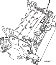
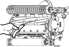
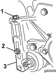
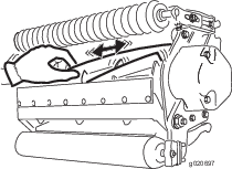
Each cutting unit has 6 grease fittings (Figure 25) that must be lubricated regularly with No. 2 lithium grease.
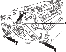
Note: Lubricating cutting units immediately after washing helps purge water out of bearings and increases bearing life.
-
Wipe each grease fitting with a clean rag.
-
Apply grease until clean grease is seen coming out of roller seals and bearing relief valve.
-
Wipe excess grease away.
Adjusting the Reel Bearings
To ensure long life of the reel bearings, periodically check if reel end play exists.
-
Loosen reel to bedknife contact by turning the bedknife adjusting knobs (Figure 26) counterclockwise until no contact exists.
-
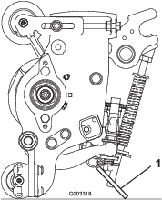
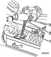
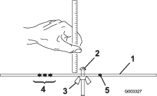
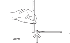
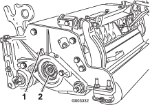
Using a rag or thickly padded glove, hold on to the reel blade and try to move the reel assembly side to side (Figure 27).
-
If end play exists, proceeded as follows:
-
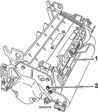
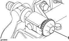
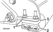
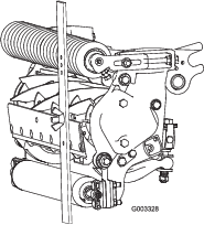
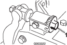
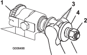
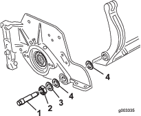
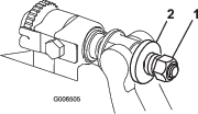
Loosen external set screw securing bearing adjusting nut to bearing housing located on the left side of the cutting unit (Figure 28).
-
Using a 1-3/8 inch socket wrench, slowly tighten the reel bearing adjustment nut until no end play of the reel exists. If the adjusting nut does not eliminate reel end play, replace the reel bearings.
Note: Reel bearings do not require preload. Overtightening the reel bearing adjuster nut will damage reel bearings.
-
-
Tighten the set screw securing bearing adjusting nut to the bearing housing. Torque the set screw to 1.4 to 1.7 N∙m (12 to 15 in-lb).
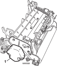
Servicing the Bedbar
Removing the Bedbar
-
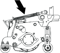
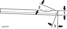
Turn bedbar adjuster screws counterclockwise to back the bedknife away from the reel (Figure 29).
-
Back out the spring tension nut, until the washer is no longer tensioned against the bedbar (Figure 29).
-
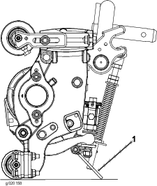
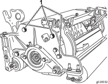
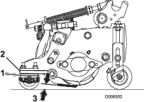
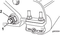
On each side of the machine, loosen the locknut securing the bedbar bolt (Figure 30).
-
Remove each bedbar bolt allowing bedbar to be pulled downward and removed from machine bolt (Figure 30).
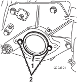
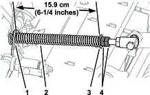
Note: Account for 2 nylon and 1 stamped steel washers on each end of bedbar (Figure 31).
Assembling the Bedbar
-
Install the bedbar, positioning the mounting ears between the washer and bedbar adjuster.
-
Secure the bedbar to each side plate with the bedbar bolts (nuts on bolts) and the 6 washers.
Note: Position a nylon washer on each side of the side plate boss. Place a steel washer outside each of the nylon washers (Figure 31).
-
Torque bedbar bolts to 27 to 36 N∙m (240 to 320 in-lb).
Note: Tighten the locknuts until the outside steel washer stops rotating and the end play is removed but, do not overtighten or deflect the side plates. Washers on the inside may have a gap.
-
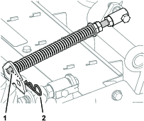
Tighten the spring tension nut until the spring is collapsed, then back off 1/2 turn (Figure 32).
Servicing the HD Dual Point Adjusters (DPA)
-
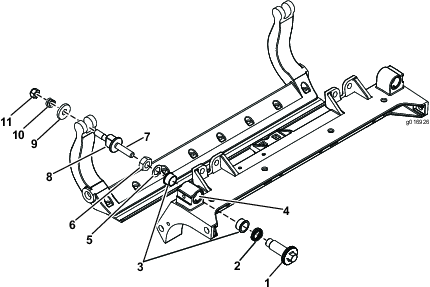
Remove all parts (refer to Installation Instructions for HD DPA Kit Model 120-7230 and to Figure 33).
-
Apply anti-sieze compound to the inside of the bushing area on cutting unit center frame (Figure 33).
-
Align the keys on flange bushings to the slots in the frame and install the bushings (Figure 33).
-
Install a wave washer onto the adjuster shaft and slide the adjuster shaft into the flange bushings in the cutting unit frame (Figure 33).
-
Secure the adjuster shaft with a flat washer and locknut (Figure 33). Torque the lock nut to 20 to 27 N∙m (15 to 20 ft-lb).
Note: The bedbar adjuster shaft has left-hand threads.
-
Apply anti-seize compound to the threads of the bedbar adjuster screw that fit into the adjuster shaft.
-
Thread bedbar adjuster screw into the adjuster shaft.
-
Loosely install the hardened washer, spring and spring tension nut onto adjuster screw.
-
Install the bedbar, positioning the mounting ears between washer and bedbar adjuster.
-
Secure the bedbar to each side plate with the bedbar bolts (nuts on bolts) and 6 washers.
Note: A nylon washer is to be positioned on each side of the side plate boss.
-
Place a steel washer outside each of the nylon washers (Figure 33).
Note: Torque bedbar bolts to 27 to 36 N∙m (240 to 320 ft-lb).
-
Tighten the locknuts until the outside steel washer stops rotating and end play is removed but do not overtighten or deflect the side plates.
Note: Washers on inside may have a gap (Figure 33).
-
Tighten the nut on each bedbar adjuster assembly until the compression spring is fully compressed, then loosen the nut 1/2 turn (Figure 33).
-
Repeat this procedure on the other end of the cutting unit.
-
Adjust the bedknife to the reel.
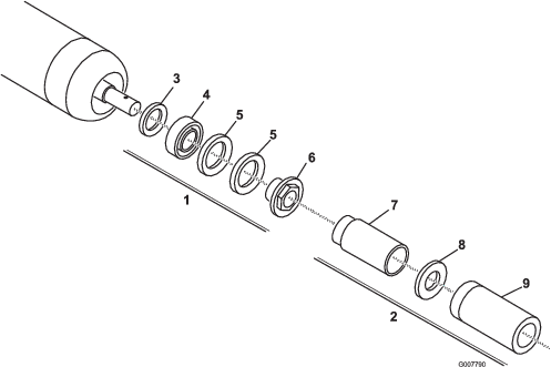
Servicing the Roller
The roller Rebuild Kit, Part No. 114-5430 and the Roller Rebuild Tool Kit, Part No. 115-0803 (Figure 34) are available for servicing the roller. The Roller Rebuild Kit includes all the bearings, bearing nuts, inner seals and outer seals to rebuild a roller. The Roller Rebuild Tool Kit includes all the tools and the installation instructions required to rebuild a roller with the roller rebuild kit. Refer to your Parts Catalog or contact your Authorized Toro Distributor for assistance.