CALIFORNIA
Proposition 65 Warning
Park the machine on a level surface.
Engage the parking brake.
Shut off the engine and remove the key.
Disconnect the battery; refer to your machine Operator’s Manual.
Hydraulic fluid escaping under pressure can penetrate skin and cause injury.
Make sure that all hydraulic fluid hoses and lines are in good condition and all hydraulic connections and fittings are tight before applying pressure to the hydraulic system.
Keep your body and hands away from pinhole leaks or nozzles that eject high-pressure hydraulic fluid.
Use cardboard or paper to find hydraulic leaks.
Safely relieve all pressure in the hydraulic system before performing any work on the hydraulic system.
Seek immediate medical attention if fluid is injected into skin.
In certain conditions, fuel is extremely flammable and highly explosive. A fire or explosion from fuel can burn you and others and can damage property.
Fill the fuel tanks outdoors, in an open area, when the engine is cold. Wipe up any fuel that spills.
Never fill the fuel tanks inside an enclosed trailer.
Never smoke when handling fuel and stay away from an open flame or where fuel fumes may be ignited by a spark.
Store fuel in an approved container and keep it out of the reach of children. Never buy more than a 30-day supply of fuel.
Do not operate the machine without the entire exhaust system in place and in proper working condition.
In certain conditions during fueling, static electricity can be released, causing a spark that can ignite the fuel vapors. A fire or explosion from fuel can burn you and others and can damage property.
Always place fuel containers on the ground away from your vehicle before filling.
Do not fill fuel containers inside a vehicle or on a truck or trailer bed, because interior carpets or plastic truck bed liners may insulate the container and slow the loss of any static charge.
When practical, remove equipment from the truck or trailer and refuel the equipment with its wheels on the ground.
If this is not possible, then refuel such equipment on a truck or trailer from a portable container rather than from a fuel-dispenser nozzle.
If you must use a fuel-dispenser nozzle, keep the nozzle in contact with the rim of the fuel tank or container opening at all times until fueling is complete.
Fuel is harmful or fatal if swallowed. Long-term exposure to vapors can cause serious injury and illness.
Avoid prolonged breathing of vapors.
Keep your face away from the nozzle and fuel tank opening.
Keep fuel away from your eyes and skin.
Refer to the following figures for this procedure:
Completely drain the hydraulic fluid from the hydraulic tank through the gear pump suction hose into a suitable container.
Label the hydraulic tank hoses for assembly purposes. Thoroughly clean the hydraulic hose ends prior to disconnecting the hoses from the tank fittings.
Remove the hose assemblies and O-rings from the hydraulic tank fittings. Allow the hoses to drain into a suitable container. Put clean caps or plugs on disconnected hoses and fittings to prevent contamination.
Perform the following steps to drain the fuel tank:
Close the fuel-shutoff valve below the fuel tank; refer to your machine Operator’s Manual.
Disconnect the fuel supply hose at the fuel filter and drain any fuel that is in the fuel filter and fuel hose into a suitable container.
Place the end of the fuel hose into a suitable container for draining the tank.
Open the fuel-shutoff valve to drain the tank, then close the valve.
Disconnect any additional hoses that connect the fuel tank to the fuel system.
If your machine is equipped with a leak detector tank, disconnect the machine wire-harness connectors from the oil level sensor and solenoid coil.
Note: For the location of the oil level sensor and solenoid coil, refer to Figure 3 in Removing the Leak Detector Tank.
Remove the 4 flange-head screws that secure the tank-mount-plate assembly to the machine frame.
Have an assistant help you to lift the tank-mount-plate assembly from the machine frame.
If your machine is equipped with a leak detector tank, refer to the following procedures in this section:
If your machine is equipped with a hydraulic tank cover, refer to the following procedures in this section:
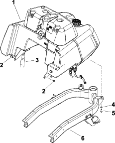
Refer to Figure 3 for this procedure.
Remove the 4 cap screws, flat washers, neoprene washers, and spacers that secure the leak detector tank to the hydraulic tank.
Thoroughly clean the overflow-hose junction and the hydraulic-tank barb. Loosen the hose clamp and disconnect the overflow hose from the tank barb.
Lift the leak detector tank slightly and clean the valve-hose junction at the 90° solenoid valve fitting. Loosen the hose clamp and disconnect the valve hose at the 90° solenoid valve fitting.
Remove the leak-detector-tank assembly from the machine.
Clean the leak detector tank and the tank components with clean solvent.
Note: Inspect the tank for leaks, cracks, or other damage.
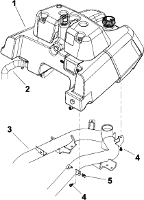
Refer to Figure 4 for this procedure.
Remove the 4 cap screws, flat washers, neoprene washers, and spacers that secure the tank cover to the hydraulic tank.
Loosen the hose clamp at the overflow hose and the hydraulic-tank barb and disconnect the hose from the barb.
Remove the tank cover from the tank-mount-plate assembly.
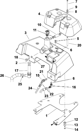
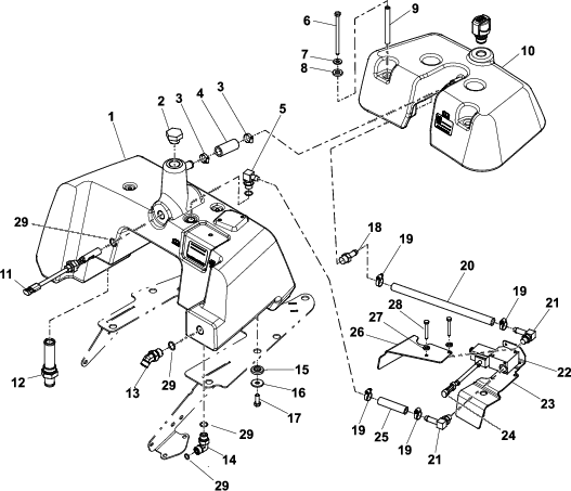
Remove the 4 cap screws, flat washers, and flange bushings that secure the fuel tank to the tank mount plate (Figure 5).

Remove the fuel tank from the mount plate.
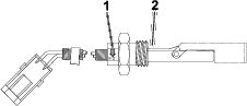
Refer to Figure 3 for this procedure.
Remove the 90° hydraulic fitting from the hydraulic tank. Note the orientation of the fitting for assembly.
Remove the 2 cap screws and lock washers that secure the solenoid-valve assembly to the hydraulic tank.
Remove the solenoid-valve assembly, shield bracket, and cover from the hydraulic tank.
Refer to Figure 3 or Figure 4 for this procedure.
Remove the 4 cap screws, flat washers, and flange bushings that secure the hydraulic tank to the tank mount plate.
Remove the existing hydraulic tank from the mount plate.
If your machine is equipped with a leak detector tank, remove the oil level sensor from the hydraulic tank. Discard the O-ring from the sensor.
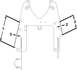
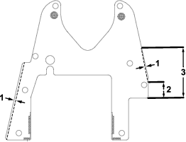
Trim 2.3 mm (0.09 inch) off of each side of the mount plate.
Use the flange-head screws that you previously removed in Removing the Tank-Mount-Plate Assembly to install the mount plate to the machine frame.
Parts needed for this procedure:
| Hydraulic tank | 1 |
| Dipstick | 1 |
If your machine is equipped with a leak detector tank, refer to the following procedures in this section:
If your machine is equipped with a hydraulic tank cover, refer to the following procedures in this section:
Refer to Figure 3 or Figure 4 for this procedure.
Remove the caps and plugs from the disconnected hydraulic hoses and tank fittings.
Lubricate and place new O-rings onto all removed fittings. Install the hydraulic fittings into the tank openings.
Note: Use the labels that you made during the removal process to properly install the hydraulic lines to the tank fittings.
Torque the 45° hydraulic fitting to 23 to 28 N∙m (17 to 21 ft-lb).
Torque the 90° hydraulic elbow fitting to 41 to 51 N∙m (30 to 38 ft-lb).
Torque the strainer to 95 to 108 N∙m (70 to 80 ft-lb).
If your machine has an equipped leak detector tank, install the oil-level sensor into the tank, ensuring that the arrow on sensor is pointing down (Figure 8). Torque the sensor nut to 12.5 to 15.8 N∙m (110 to 140 in-lb).
Position the hydraulic tank onto the tank mount plate.
Apply anti-seize compound to the threads of the 4 cap screws.
Secure the hydraulic tank to the tank mount plate with 4 cap screws, flat washers, and flange bushings.
Torque the cap screws to 3 to 6 N∙m (30 to 50 in-lb)
Use the previously removed cap screws, flat washers, and flange bushings to secure the fuel tank to the tank mount plate; refer to Figure 5 in Removing the Fuel Tank.
Connect and secure all fuel hoses.
Refer to Figure 3 in Removing the Leak Detector Tank for this procedure.
Apply anti-seize compound to the end threads of the 2 cap screws used to secure the solenoid-valve assembly to the hydraulic tank.
Position the cover, solenoid-valve assembly, and shield bracket to the hydraulic tank. Orientate the solenoid valve assembly so the solenoid coil is closer to the front of the tank.
Secure the solenoid-valve assembly to the hydraulic tank with 2 cap screws and lock washers. Torque the cap screws to 3 to 7 N∙m (30 to 60 in-lb).
Install the 90° hydraulic fitting to the hydraulic tank.
Torque the hydraulic fitting to 23 to 28 N∙m (17 to 21 ft-lb).
Use a hose clamp to connect the valve hose to the straight barb fitting.
Position the leak-detector-tank assembly over the hydraulic tank and connect the valve hose to the 90° solenoid valve fitting. Secure the hose to the fitting with a hose clamp.
Connect the overflow hose to the leak-detector-tank barb and secure it with a hose clamp.
Apply anti-seize lubricant to the end threads of the 4 cap screws that are used to secure the leak detector tank to the hydraulic tank.
Important: Do not overtighten the cap screws when you secure the leak detector tank to the hydraulic tank. The threads in the tank may become damaged.
Secure the leak detector tank to the hydraulic tank with 4 cap screws, spacers, neoprene washers, and flat washers.
Torque the cap screws to 3 to 6 N∙m (30 to 50 in-lb).
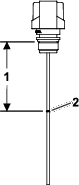
Trim the dipstick to the marked trim line at 9.5 cm (3-3/4 inches) as shown in Figure 9, then install the dipstick into the leak-detector-tank opening.
Refer to Figure 4 in Removing the Hydraulic Tank Cover for this procedure.
Position the tank cover to the top of the hydraulic tank.
Connect the overflow hose to the hydraulic-tank barb and secure it with a hose clamp.
Apply anti-seize compound to the 4 cap-screw threads. Secure the tank cover to the hydraulic tank with 4 cap screws, spacers, flat washers, and neoprene washers.
Torque the cap screws to 3 to 6 N∙m (30 to 50 in-lb).
Install the new dipstick onto the hydraulic-tank opening.
Open the fuel-shutoff valve on the fuel tank.
Fill the fuel tank with fuel; refer to your machine Operator’s Manual.
Fill the hydraulic tank with new hydraulic fluid; refer to your machine Operator’s Manual.
If your machine has an equipped leak detector tank:
Connect the oil-level-sensor wire connector to the machine wire harness.
Ensure that the leak detector system is operating; refer to your machine Operator’s Manual
Connect the battery; refer to your machine Operator’s Manual.