Use the appropriate kit for your monitor as follows:
X25 monitor—Model No. 136-0461
X30 monitor—Model No. 136-0462
CALIFORNIA
Proposition 65 Warning
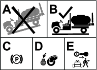
Park the machine on a level surface.
Engage the parking brake.
Shut off the engine and remove the key.
Parts needed for this procedure:
| Monitor visor | 1 |
| Threaded standoff | 1 |
| Adhesive strip | 2 |
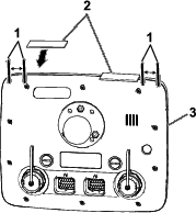
Remove the backing from the 2 adhesive strips.
At the top of the sprayer monitor, align the strips to the sprayer monitor as shown in Figure 2.
Firmly press the adhesive strips to the top of the monitor.
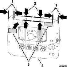
Remove the backing from the 2 adhesive strips.
At the back of the sprayer monitor, align the adhesive strips to the sprayer monitor as shown in Figure 3.
Firmly press the adhesive strips to the back of the monitor.
At the back of the sprayer monitor and with the 2 connectors (26 pin) aligned down, remove the top locknut (5 mm) from the stud for the ball-pivot fitting (A of Figure 4).
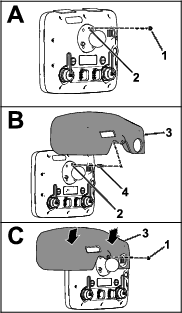
Apply a coat of thread-locking compound (wicking—medium-high strength) to the threads for the nut portion of the threaded standoff (Figure 5).
Thread the standoff into the stud for the ball-pivot fitting (B of Figure 4) and torque the standoff to 250 N∙cm (22 in-lb).
Apply a coat of thread-locking compound (wicking—medium-high strength) to the threads for the stud portion of the threaded standoff (Figure 5).
Remove the backing from the 2 adhesive strips that you applied in Applying the Adhesive Strips to the X25 Sprayer Monitor.
Align the hole in the display hood with the stud portion of the threaded standoff (B of Figure 4).
Assemble the hood to the monitor (C of Figure 4) with the locknut (5 mm) that you removed in step 1.
Note: Press down on the areas of the top of the hood with the adhesive strips underneath.
Torque the nut to 250 N∙cm (22 in-lb).
At the back of the sprayer monitor and with the 2 connectors (26 pin) aligned down, remove the top locknut (5 mm) from the stud for the ball-pivot fitting (A of Figure 6).
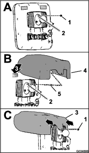
Apply a coat of thread-locking compound (wicking—medium-high strength) to the threads for the nut portion of the threaded standoff (Figure 7).
Thread the standoff into the stud for the ball-pivot fitting (B of Figure 6) and torque the standoff to 250 N∙cm (22 in-lb).
Apply a coat of thread-locking compound (wicking—medium-high strength) to the threads for the stud portion of the threaded standoff (Figure 7).
Remove the backing from the 2 adhesive strips (B of Figure 6) that you applied in Applying the Adhesive Strips to the X30 Sprayer Monitor.
Align the hole in the display hood with the stud portion of the threaded standoff (B of Figure 6).
Assemble the hood to the monitor (C of Figure 6) with the locknut (5 mm) that you removed in step 1.
Note: Press down the corners for the hood that are located above the 2 adhesive strips.
Torque the nut to 250 N∙cm (22 in-lb).