

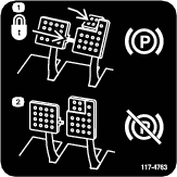


 is displayed in the InfoCenter,
an assist regeneration is in progress.
is displayed in the InfoCenter,
an assist regeneration is in progress. is displayed in the InfoCenter,
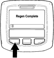
a regeneration is in progress.
is displayed in the InfoCenter,
a regeneration is in progress. is displayed in the InfoCenter,
a regeneration is requested.
is displayed in the InfoCenter,
a regeneration is requested. is displayed in the InfoCenter,
a recovery regeneration is requested.
is displayed in the InfoCenter,
a recovery regeneration is requested.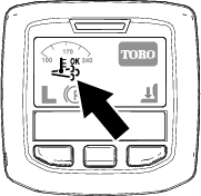
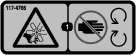
 icon displays in the InfoCenter while the assist
regeneration is processing.
icon displays in the InfoCenter while the assist
regeneration is processing.

 is running and above 60C/140F message displays. (
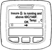


Maintenance
Note: Determine the left and right sides of the machine from the normal operating position.
Recommended Maintenance Schedule(s)
| Maintenance Service Interval | Maintenance Procedure |
|---|---|
| After the first 8 operating hours |
|
| After the first 200 operating hours |
|
| Before each use or daily |
|
| Every 50 hours |
|
| Every 100 hours |
|
| Every 200 hours |
|
| Every 250 hours |
|
| Every 400 hours |
|
| Every 800 hours |
|
| Before storage |
|
Service Interval Chart
Caution
If you leave the key in the ignition switch, someone could accidently start the engine and seriously injure you or other bystanders.
Remove the key from the ignition before you do any maintenance.
Pre-Maintenance Procedures
Pre-Maintenance Safety
-
Before adjusting, cleaning, repairing, or leaving the machine, do the following:
-
Park the machine on a level surface.
-
Move the throttle switch to the low-idle position.
-
Disengage the cutting units.
-
Lower the cutting units.
-
Ensure that the traction is in neutral.
-
Engage the parking brake.
-
Shut off the engine and remove the key.
-
Wait for all moving parts to stop.
-
Allow machine components to cool before performing maintenance.
-
-
If possible, do not perform maintenance while the engine is running. Keep away from moving parts.
-
Use jack stands to support the machine or components when required.
-
Carefully release pressure from components with stored energy.
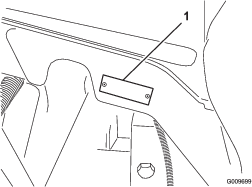
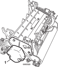
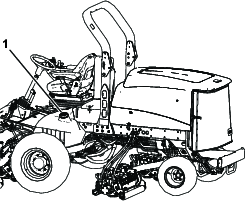
Removing the Hood
-
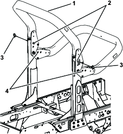
Release the hood latches (Figure 66) and pivot open the hood.
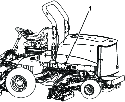
-
Remove the cotter pins securing the rear hood brackets to the frame pins and lift off the hood.
Lubrication
Greasing the Bearings and Bushings
The machine has grease fittings that must be lubricated regularly with No.2 lithium grease. If the machine is operated under normal conditions, lubricate all bearings and bushings after every 50 hours of operation or immediately after every washing.
The grease fitting locations and quantities are as follows:
-
Brake shaft pivot bearings (5) (Figure 67)
-
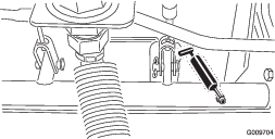
Rear axle pivot bushings (2) (Figure 68)
-
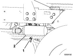
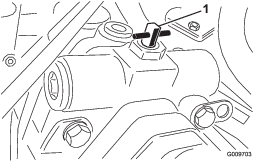
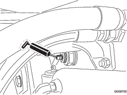
Steering cylinder ball joints (2) (Figure 69)
-
Tie rod ball joints (2) (Figure 69)
-
King pin bushings (2) (Figure 69). The top fitting on the king pin should only be lubricated annually (2pumps).
-
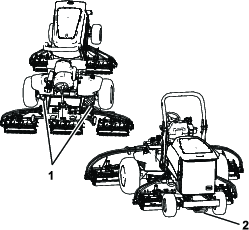
Lift arm bushings (1 per cutting unit) (Figure 70)
-
Lift cylinder bushings (2 per cutting unit) (Figure 70)
-
Lift arm pivot bushings (1 per cutting unit) (Figure 71)
-
Cutting unit carrier frame (2 per cutting unit) (Figure 71)
-
Cutting unit lift arm pivot (1 per cutting unit) (Figure 71)
Engine Maintenance
Engine Safety
-
Shut off the engine before checking the oil or adding oil to the crankcase.
-
Do not change the governor speed or overspeed the engine.
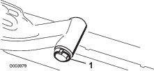
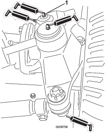
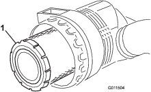
Servicing the Air Cleaner
Check the air-cleaner body for damage which could cause an air leak. Replace it if it is damaged. Check the whole intake system for leaks, damage, or loose hose clamps.
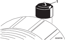
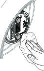
Service the air-cleaner filter only when the service indicator (Figure 72) requires it. Changing the air filter before it is necessary only increases the chance of dirt entering the engine when the filter is removed.
Important: Be sure that the cover is seated correctly and seals with the air-cleaner body.
-
Park the machine on a level surface, lower the cutting units, engage the parking brake, shut off the engine, and remove the key.
-
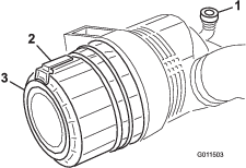
Pull the latch outward and rotate the air-cleaner cover counterclockwise (Figure 73).
-
Remove the cover from the air-cleaner body.
-
Before removing the filter, use low-pressure air—275 kPa (40 psi), clean and dry—to help remove large accumulations of debris packed between outside of primary filter and the canister. Avoid using high-pressure air, which could force dirt through the filter into the intake tract.
This cleaning process prevents debris from migrating into the intake when the primary filter is removed.
-
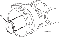
Remove and replace the primary filter (Figure 74).
Cleaning of the used element is not recommended due to the possibility of damage to the filter media. Inspect the new filter for shipping damage, checking the sealing end of the filter and the body. Do not use a damaged element.
Insert the new filter by applying pressure to the outer rim of the element to seat it in the canister. Do not apply pressure to the flexible center of the filter.
Important: Never attempt to clean the safety filter (Figure 75). Replace the safety filter with a new one after every 3 primary filter services.
-
Clean the dirt-ejection port located in the removable cover.
-
Remove the rubber outlet valve from the cover, clean the cavity, and install the outlet valve.
-
Install the cover, orienting the rubber outlet valve in a downward position—between approximately 5 o’clock to 7 o’clock when viewed from the end.
-
Reset the indicator (Figure 72) if it shows red.
Servicing the Engine Oil
Oil Specification
Use high-quality, low-ash engine oil that meets or exceeds the following specifications:
-
API service category CJ-4 or higher
-
ACEA service category E6
-
JASO service category DH-2
Important: Using engine oil other than API CJ-4 or higher, ACEA E6, or JASO DH-2 may cause the diesel particulate filter to plug or cause engine damage.
Use the following engine oil viscosity grade:
-
Preferred oil: SAE 15W-40 (above 0°F)
-
Alternate oil: SAE 10W-30 or 5W-30 (all temperatures)
Toro Premium Engine Oil is available from your Authorized Toro Distributor in either 15W-40 or 10W-30 viscosity grades. See the parts catalog for part numbers.
Close sectionChecking the Engine-Oil Level
The engine is shipped with oil in the crankcase; however, the oil level must be checked before and after the engine is first started.
Important: Check the engine oil daily. If the engine-oil level is above the Full mark on the dipstick, the engine oil may be diluted with fuel;If the engine oil level is above the Full mark, change the engine oil.
The best time to check the engine oil is when the engine is cool before it has been started for the day. If it has already been run, allow the oil to drain back down to the sump for at least 10 minutes before checking. If the oil level is at or below the Add mark on the dipstick, add oil to bring the oil level to the Full mark. Do not overfill the engine with oil.
Important: Keep the engine oil level between the upper and lower limits on the dipstick; the engine may fail if you run it with too much or too little oil.
-
Park the machine on a level surface.
-
Unlock the hood latches and open the hood.
-
Remove the dipstick, wipe it clean, install the dipstick into the tube, and pull it out again.
The oil level should be in the safe range (Figure 76).

-
If the oil is below the safe range, remove the fill cap (Figure 76) and add oil until the level reaches the Full mark.
Important: Do not overfill the engine with oil.
Note: When using different oil, drain all old oil from the crankcase before adding new oil.
-
Install the oil-fill cap and dipstick.
-
Close the hood and secure it with the latches.
Crankcase Oil Capacity
5.7 L (6.0 US qt) with the filter.
Close sectionChanging the Engine Oil and Filter
-
Park the machine on a level surface, lower the cutting units, engage the parking brake, shut off the engine, and remove the key.
-
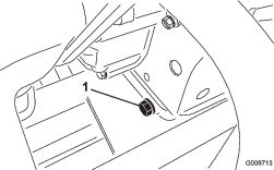
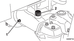
Remove the drain plug (Figure 77) and let the oil flow into a drain pan.
-
Install the drain plug when the oil stops.
-
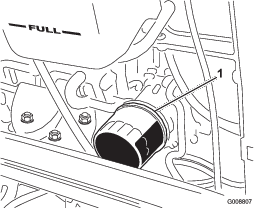
Remove the oil filter (Figure 78).
-
Apply a light coat of clean oil to the new filter seal before installing it.
Note: Do not overtighten the filter.
-
Add oil to the crankcase; refer to Checking the Engine-Oil Level.
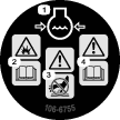
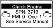
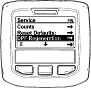
Servicing the Diesel-Oxidation Catalyst (DOC) and the Soot Filter
-
If advisory message displays in the InfoCenter, the DPF is nearing the recommended point for servicing the diesel-oxidation catalyst and the soot filter.
-
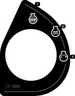
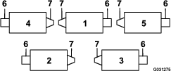
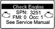
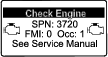
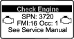
If engine faults , , or in the InfoCenter (Figure 80) display in the InfoCenter, clean the soot filter using the steps that follow:
-
Refer to the Engine section in the Service Manual for information on disassembling and assembling the diesel-oxidation catalyst and the soot filter of the DPF.
-
Refer to your Authorized Toro Distributor for diesel-oxidation catalyst and the soot filter replacement parts or service.
-
Contact your Authorized Toro Distributor to have them reset the engine ECU after you install a clean DPF.
-
Fuel System Maintenance
Danger
Under certain conditions, fuel and fuel vapors are highly flammable and explosive. A fire or explosion from fuel can burn you and others and can cause property damage.
-
Fill the fuel tank outdoors, in an open area, when the engine is off and is cold. Wipe up any fuel that spills.
-
Do not fill the fuel tank completely full. Add fuel to the fuel tank until the level is 25mm (1inch) below the top of the tank, not the filler neck. This empty space in the tank allows the fuel to expand.
-
Never smoke when handling fuel, and stay away from an open flame or where fuel fumes may be ignited by a spark.
-
Store fuel in a clean, safety-approved container and keep the cap in place.
Draining the Fuel Tank
Park the machine on a level surface, lower the cutting units, engage the parking brake, shut off the engine, and remove the key.
Drain and clean the fuel tank if the fuel system becomes contaminated or if the machine is to be stored for an extended period. Use clean fuel to flush out the tank.
Close sectionChecking the Fuel Lines and Connections
Park the machine on a level surface, lower the cutting units, engage the parking brake, shut off the engine, and remove the key.
Inspect the fuel lines for deterioration, damage, or loose connections.
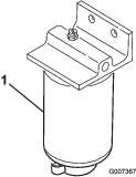
Close sectionServicing the Water Separator
-
Park the machine on a level surface, lower the cutting units, engage the parking brake, shut off the engine, and remove the key.
-
Place a clean container under the fuel filter.
-
Loosen the drain plug on the bottom of the filter canister.
-
Clean the area where the filter canister mounts.
-
Remove the filter canister and clean the mounting surface.
-
Lubricate the gasket on the filter canister with clean oil.
-
Install the filter canister by hand until the gasket contacts mounting surface, then rotate it an additional 1/2 turn.
-
Tighten the drain plug on the bottom of the filter canister.
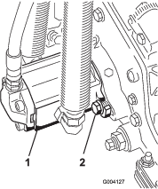
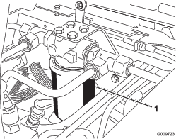
Servicing the Fuel Filter
The engine fuel filter should be replaced after every 400 hours of operation.
-
Park the machine on a level surface, lower the cutting units, engage the parking brake, shut off the engine, and remove the key.
-
Clean the area around the fuel-filter head (Figure 82).
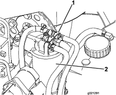
-
Remove the filter and clean the filter-head mounting surface (Figure 82).
-
Lubricate the filter gasket with clean lubricating engine oil. Refer to the engine owner’s manual, included with the machine, for additional information.
-
Install the dry filter canister, by hand, until the gasket contacts the filter head, then rotate it an additional 1/2 turn.
-
Start the engine and check for fuel leaks around the filter head.
Cleaning the Fuel-Intake Screen
Park the machine on a level surface, lower the cutting units, engage the parking brake, shut off the engine, and remove the key.
The fuel-intake tube, located inside the fuel tank, is equipped with a screen to help prevent debris from entering the fuel system. Remove the fuel-intake tube and clean the screen as required.
Close sectionElectrical System Maintenance
Electrical System Safety
-
Disconnect the battery before repairing the machine. Disconnect the negative terminal first and the positive last. Connect the positive terminal first and the negative last.
-
Charge the battery in an open, well-ventilated area, away from sparks and flames. Unplug the charger before connecting or disconnecting the battery. Wear protective clothing and use insulated tools.
Warning
Battery posts, terminals, and related accessories contain lead and lead compounds, chemicals known to the State of California to cause cancer and reproductive harm. Wash hands after handling.
Charging and Connecting the Battery
-
Park the machine on a level surface, lower the cutting units, engage the parking brake, shut off the engine, and remove the key.
-
Unlatch and raise the operator's console panel (Figure 83).
Danger
Battery electrolyte contains sulfuric acid, which is fatal if consumed and causes severe burns.
-
Do not drink electrolyte and avoid contact with skin, eyes, or clothing. Wear safety glasses to shield your eyes and rubber gloves to protect your hands.
-
Fill the battery where clean water is always available for flushing the skin.
-
-
Connect a 3 to 4 A battery charger to the battery posts.
-
Charge the battery at a rate of 3 to 4 A for 4 to 8 hours.
-
When the battery is charged, disconnect the charger from the electrical outlet and battery posts.
Warning
Charging the battery produces gasses that can explode.
Never smoke near the battery and keep sparks and flames away from battery.
-
Install the positive cable (red) to the positive (+) terminal and the negative cable (black) to the negative (-) terminal of the battery (Figure 84).
-
Secure the cables to the posts with cap screws and nuts.
Make sure that the positive (+) terminal is all of the way onto the post and the cable is positioned snug to the battery. The cable must not contact the battery cover.
-
Slide the rubber boot over the positive terminal to prevent a possible short from occurring.
-
Coat both battery connections with Grafo 112X (skin-over) grease, Toro Part No. 505-47, petroleum jelly, or light grease to prevent corrosion.
-
Slide the rubber boot over the positive terminal.
-
Close the console panel and secure the latch.
Warning
Battery terminals or metal tools could short against metal components causing sparks. Sparks can cause the battery gasses to explode, resulting in personal injury.
-
When removing or installing the battery, do not allow the battery terminals to touch any metal parts of the machine.
-
Do not allow metal tools to short between the battery terminals and metal parts of the machine.
Warning
Incorrect battery cable routing could damage the machine and cables causing sparks. Sparks can cause the battery gasses to explode, resulting in personal injury.
-
Always disconnect the negative (black) battery cable before disconnecting the positive (red) cable.
-
Always connect the positive (red) battery cable before connecting the negative (black) cable.
-
Servicing the Battery
Important: Before welding on the machine, disconnect the negative cable from the battery to prevent damage to the electrical system.
Note: Check the battery condition weekly or after every 50 hours of operation. Keep the terminals and the entire battery case clean because a dirty battery will discharge slowly.
Clean the battery as follows:
-
Park the machine on a level surface, lower the cutting units, engage the parking brake, shut off the engine, and remove the key.
-
Remove the battery from the machine.
-
Wash the entire case with a solution of baking soda and water.
-
Rinse the case with clean water.
-
Coat the battery posts and cable connectors with Grafo 112X (skin-over) grease (Toro Part No. 505-47) or petroleum jelly to prevent corrosion.
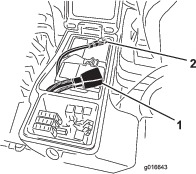
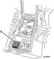
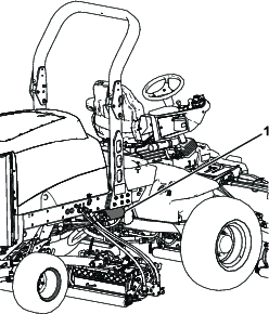
Checking the Fuses
The fuses are located under the operator’s control panel.
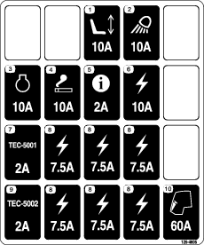
Park the machine on a level surface, lower the cutting units, engage the parking brake, shut off the engine, and remove the key.
Unhook the latch and raise the operator's console panel (Figure 86) to expose the fuses (Figure 87).
Drive System Maintenance
Checking the Torque of the Wheel Nuts
Park the machine on a level surface, lower the cutting units, engage the parking brake, shut off the engine, and remove the key.
Warning
Failure to maintain proper torque of the wheel nuts could result in failure or loss of a wheel and may result in personal injury.
Torque the front and rear wheel nuts to 115 to 136N∙m (85 to 100ft-lb) after 1 to 4 hours of operation and again after 8 hours of operation. Torque the wheel nuts every 200 hours thereafter.
Note: The front wheel nuts are 1/2–20 UNF. The rear wheel nuts are M12 x 1.6-6H (metric).
Close sectionChecking for End-Play in the Planetary Drives
There should be no end-play in the planetary drives/drive wheels (i.e., the wheels should not move when you pull or push them in a direction parallel to the axle).
-
Park the machine on a level surface, engage the parking brake, lower the cutting units, shut off the engine, and remove the key.
-
Chock the rear wheels and raise the front of machine, supporting the front axle/frame on jack stands.
Danger
A machine on a jack may be unstable and slip off the jack, injuring anyone beneath it.
-
Do not start the engine while the machine is on a jack.
-
Always remove the key from the switch before getting off the machine.
-
Block the tires when you are raising the machine with a jack.
-
Support the machine with jack stands.
-
-
Grasp 1 of the front drive wheels and push/pull it toward and away from the machine, noting any movement.

-
Repeat step 3 for the other drive wheel.
-
If either wheel moves, contact your authorized Toro distributor to have the planetary drive rebuilt.
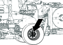
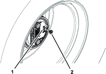
Checking the Planetary Gear-Drive Lubricant
Lubricant Specification: high quality SAE 85W-140 gear lubricant
-
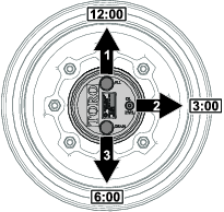
Park the machine on level surface, position the wheel so that the fill plug is at the 12 o'clock position, the check plug is at 3 o'clock position, and the drain plug is at the 6 o'clock position (Figure 90).
-
Remove the check plug at the 3 o’clock position (Figure 90).
The oil level should be at the bottom of the check-plug hole.
-
If the oil level is low, remove the fill plug at the 12 o’clock position and add oil until it begins to flow out of the hole at the 3 o’clock position.
-
Check the O-ring for the plug(s) for wear or damage.
Note: Replace the O-ring(s) as needed.
-
Install the plug(s).
-
Repeat steps 1 through 5 on the planetary gear assembly at the other side of the machine.
Changing the Planetary-Gear-Drive Oil
Lubricant specification: high quality SAE 85W-140 gear lubricant
Planetary and brake housing lubrication capacity: 0.65 L (22 fl oz)
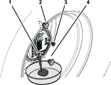
Draining the Planetary-Gear-Drive
-
Park the machine on level surface, position the wheel so that the fill plug is at the 12 o'clock position, the check plug is at 3 o'clock position, and the drain plug is at the 6 o'clock position; refer to Figure 90 in Checking the Planetary Gear-Drive Lubricant.
-
Remove the fill plug at the 12 o’clock position and the check plug at the 3 o’clock position (Figure 92).
-
Place a drain pan under the planetary hub, remove the drain plug at the 6 o’clock position, and allow the oil to fully drain (Figure 92).
-
Check the O-rings for the fill, check, and drain plugs for wear or damage.
Note: Replace the O-ring(s) as needed.
-
Install the drain plug into the drain hole of the planetary housing (Figure 92).
-
Place a drain pan under the brake housing, remove the drain plug, and allow the oil to fully drain (Figure 93).
-
Check the O-ring for the plug for wear or damage and install the drain plug into the brake housing.
Note: Replace the O-ring as needed.
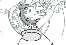
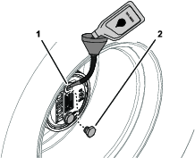
Filling the Planetary-Gear-Drive with Lubricant
-
Through the fill-plug hole, slowly fill the planetary with 0.65 L (22 fl oz) of high quality SAE 85W-140 wt gear lube.
Important: If the planetary fills before the 0.65 L (22 fl oz) of oil is added, wait 1 hour or install the plug and move the machine approximately ten feet to distribute the oil through the brake system. Then, remove the plug and add the remaining oil.
-
Install the fill plug and the check plug.
-
Wipe clean the planetary and brake housings (Figure 95).
-
Repeat steps 1 through 7 in Draining the Planetary-Gear-Drive and steps 1 through 3 in this procedure for the planetary/brake assembly at the other side of the machine.
Checking the Oil Level of the Rear Axle
The rear axle is shipped from the factory filled with SAE 85W-140gear lube. Check the oil level before the engine is first started and every 400 hours thereafter. The capacity is 2.4 L (80fl oz). Visually inspect for leaks daily.
-
Park the machine on a level surface, lower the cutting units, engage the parking brake, shut off the engine, and remove the key.
-
Remove a check plug from 1 end of the axle (Figure 96) and make sure that the oil is up to the bottom of the hole. If the level is low, remove the fill plug (Figure 96) and add enough oil to bring the level up to the bottom of the check-plug holes.
Changing the Oil in the Rear Axle
-
Park the machine on a level surface, lower the cutting units, engage the parking brake, shut off the engine, and remove the key.
-
Clean the area around the 3 drain plugs, 1 on each end and 1 in the center (Figure 97).
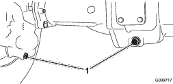
-
Remove the oil-level-check plugs and the main axle vent cap to ease in draining of the oil.
-
Remove the drain plugs and allow the oil to drain into the pans.
-
Install the plugs.
-
Remove a check plug and fill the axle with approximately 2.37 L (80 fl oz) of 85W-140 gear lube or until the oil is up to the bottom of the hole.
-
Install the check plug.
Checking the Lubricant in the Gear Box of the Rear Axle
The gear box is filled with SAE 85W-140 gear lube. Check the oil level before the engine is first started and every 400 hours thereafter. The capacity is 0.5 L (16 fl oz). Visually inspect for leaks daily.
-
Park the machine on a level surface, lower the cutting units, engage the parking brake, shut off the engine, and remove the key.
-
Remove the check/fill plug from the left side of the gear box (Figure 98) and make sure that lubricant is up to the bottom of the hole. If the level is low, add enough lubricant to bring the level up to the bottom of the hole.
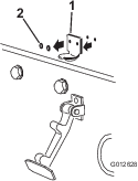
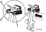
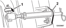
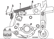
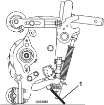
Adjusting the Traction Drive for Neutral
The machine must not creep when the traction pedal is released. If it does creep, an adjustment is required.
-
Park the machine on a level surface, shut off the engine, position the speed control into the low range, and lower the cutting units.
-
Press only the right brake pedal and engage the parking brake.
-
Jack up the left side of the machine until the left front tire is off the shop floor. Support the machine with jack stands to prevent it from falling accidentally.
-
Start the engine and allow it run at low idle.
-
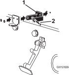
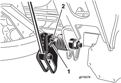
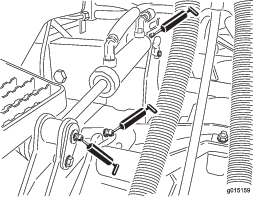
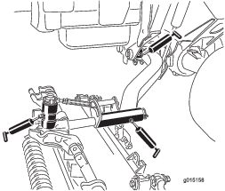
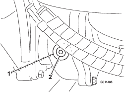
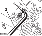
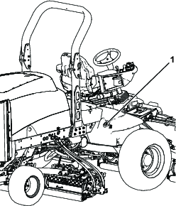
Adjust the jam nuts on the pump rod end to move the pump control tube forward to eliminate forward creep or rearward to eliminate rearward creep (Figure 99).
-
After the wheel rotation ceases, tighten the jam nuts to secure the adjustment.
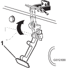
-
Shut off the engine and release the right brake.
-
Remove the jack stands and lower the machine to the shop floor.
-
Test drive the machine to ensure that it does not creep.
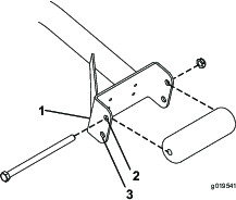
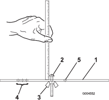
Checking the Rear-Wheel Toe-In
-
Park the machine on a level surface, lower the cutting units, engage the parking brake, shut off the engine, and remove the key.
-
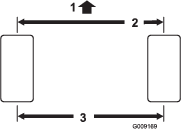
Measure the center-to-center distance (at axle height) at the front and rear of the steering tires.
Note: The front measurement must be 3mm (1/8inch) less than the rear measurement (Figure 100).
-
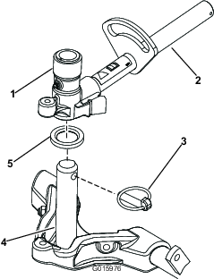
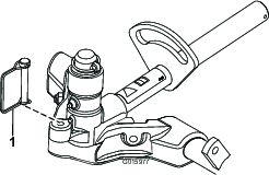
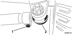
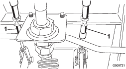
To adjust the toe-in, remove the cotter pin and the nut from either tie-rod ball joint (Figure 101).
-
Remove the tie-rod ball joint from the axle case support.
-
Loosen the clamps at both ends of the tie rods (Figure 101).
-
Rotate the detached ball joint inward or outward 1 complete revolution.
-
Tighten the clamp at the loose end of the tie rod.
-
Rotate the entire tie-rod assembly the same direction (inward or outward) 1 complete revolution.
-
Tighten the clamp at the connected end of the tie rod.
-
Install the ball joint in the axle case support and tighten the nut finger tight.
-
Measure the toe-in.
-
Repeat the procedure if necessary.
-
Tighten the nut and install a new cotter pin when the adjustment is correct.
Cooling System Maintenance
Cooling System Safety
-
Swallowing engine coolant can cause injury or death; keep out of reach from children and pets.
-
Discharge of hot, pressurized coolant or touching a hot radiator and surrounding parts can cause severe burns.
-
Always allow the engine to cool at least 15 minutes before removing the radiator cap.
-
Use a rag when opening the radiator cap, and open the cap slowly to allow steam to escape.
-
Servicing the Engine Cooling System
Remove debris from the engine area, oil cooler, and radiator daily. Clean them more frequently in dirty conditions.
-
Park the machine on a level surface, lower the cutting units, engage the parking brake, shut off the engine, and remove the key.
-
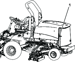
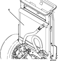
Unlatch and swing open the rear screen (Figure 102).
-
Clean the screen thoroughly of all debris.
Note: To remove the screen, lift off the hinge pins.
-
Clean both sides of the oil cooler/radiator area (Figure 103) thoroughly with compressed air. Start from the front and blow the debris out toward the back. Then clean from the back side and blow toward the front. Repeat the procedure several times until all chaff and debris is removed.
Important: Cleaning the oil cooler/radiator with water will promote premature corrosion damage to components and compact debris.
-
Close the rear screen and secure it with the latch.
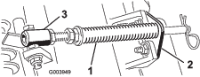
Brake Maintenance
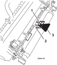
Adjusting the Service Brakes
Adjust the service brakes when there is more than 13mm (1/2inch) of free travel of the brake pedal, or when the brakes do not work effectively. Free travel is the distance the brake pedal moves before braking resistance is felt.
-
Park the machine on a level surface, lower the cutting units, engage the parking brake, shut off the engine, and remove the key.
-
Disengage the locking latch from the brake pedals so that both pedals work independently of each other.
-
To reduce free travel of the brake pedals, tighten the brakes as follows:
-
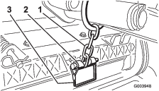
Loosen the front nut on the threaded end of the brake cable (Figure 104).
-
Tighten the rear nut to move the cable backward until the brake pedals have 0 to 13mm (0 to 1/2inch) of free travel.
Note: Make sure that there is no brake tension when the pedal is released.
-
Tighten the front nuts after the brakes are adjusted correctly.
-
Belt Maintenance
Servicing the Alternator Belt
Check the condition and tension of the belts (Figure 105) after every 100 operating hours.
-
Park the machine on a level surface, lower the cutting units, engage the parking brake, shut off the engine, and remove the key.
-
Proper tension will allow 10mm (3/8inch) deflection when a force of 45 N (10lb) is applied on the belt midway between the pulleys.
-
If the deflection is not 10mm (3/8inch), loosen the alternator mounting bolts (Figure 105).
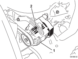
-
Increase or decrease the tension of the alternator belt and tighten the bolts.
-
Check the deflection of the belt again to ensure that the tension is correct.
Hydraulic System Maintenance
Hydraulic System Safety
-
Ensure that all hydraulic-fluid hoses and lines are in good condition and all hydraulic connections and fittings are tight before applying pressure to the hydraulic system.
-
Keep your body and hands away from pinhole leaks or nozzles that eject high-pressure hydraulic fluid.
-
Use cardboard or paper to find hydraulic leaks.
-
Safely relieve all pressure in the hydraulic system before performing any work on the hydraulic system.
-
Seek immediate medical attention if fluid is injected into skin. Injected fluid must be surgically removed within a few hours by a doctor.
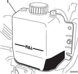
Checking the Level of the Hydraulic Fluid
The reservoir is filled at the factory with approximately 28.4 L (7.5 US gallons) of high-quality hydraulic fluid. Check the level of the hydraulic fluid before the engine is first started and daily thereafter.
The recommended replacement fluid is Toro Premium All Season Hydraulic Fluid (available in 5-gallon pails or 55-gallon drums. See parts catalog or Toro distributor for part numbers).
Alternative fluids: If the Toro fluid is not available, other conventional, petroleum-based fluids may be used, provided that they meet all of the following material properties and industry specifications. Check with your oil supplier to see whether the fluid meets these specifications.
Note: Toro will not assume responsibility for damage caused by improper substitutions, so use only products from reputable manufacturers who will stand behind their recommendation.
| High Viscosity Index/Low Pour Point Antiwear Hydraulic Fluid, ISO VG 46 Multigrade | |||
| Material Properties: | |||
| Viscosity, ASTM D445 | cSt @ 40°C (104°F) 44 to 50cSt @ 100°C (212°F) 7.9 to 9.1 | ||
| Viscosity index, ASTM D2270 | 140 or higher (high viscosity index indicates a multiweight fluid) | ||
| Pour point, ASTM D97 | -37°C to -45°C (-34°F to -49°F) | ||
| FZG, fail stage | 11 or better | ||
| Water content (new fluid) | 500 ppm (maximum) | ||
| Industry Specifications: | |||
| Vickers I-286-S, Vickers M-2950-S, Denison HF-0, Vickers 35 VQ 25 (Eaton ATS373-C) | |||
The proper hydraulic fluids must be specified for mobile machinery (as opposed to industrial plant usage), multiweight-type, with ZnDTP or ZDDP anti-wear additive package (not an ashless-type fluid).
Important: The ISO VG 46 Multigrade fluid has been found to offer optimal performance in a wide range of temperature conditions. For operation in consistently high ambient temperatures, 18° C (65° F) to 49° C (120° F), ISO VG 68 hydraulic fluid may offer improved performance.
Premium Biodegradable Hydraulic Fluid-Mobil EAL EnviroSyn 46H
Important: Mobil EAL EnviroSyn 46H is the only synthetic biodegradable fluid approved by Toro. This fluid is compatible with the elastomers used in Toro hydraulic systems and is suitable for a wide range of temperature conditions. This fluid is compatible with conventional fluids, but for maximum biodegradability and performance the hydraulic system should be thoroughly flushed of conventional fluid. The fluid is available in 19 L (5 US gallon) containers or 208 L (55 US gallon) drums from your Mobil Distributor.
Important: Many hydraulic fluids are almost colorless, making it difficult to spot leaks. A red dye additive for the hydraulic fluid is available in 20 ml (2/3 fl oz) bottles. A bottle is sufficient for 15 to 22 L (4 to 6 US gallons) of hydraulic fluid. Order part 44-2500 from your Authorized Toro Distributor.
-
Position the machine on a level surface, lower the cutting units, stop the engine, and remove the key.
-
Clean the area around the filler neck and cap of the hydraulic tank (Figure 106).
-
Remove the cap from the filler neck.
-
Remove the dipstick from the filler neck and wipe it with a clean rag.
-
Insert the dipstick into the filler neck; then remove it and check the fluid level.
The fluid level should be between the 2 marks on the dipstick.
-
If the level is low, add the appropriate fluid to raise the level to the upper mark.
-
Install the dipstick and cap onto the filler neck.
Changing the Hydraulic Fluid
Change the hydraulic fluid after every 800 operating hours, in normal conditions. If the fluid becomes contaminated, contact your local Toro distributor because the system must be flushed. Contaminated fluid looks milky or black when compared to clean fluid.
-
Park the machine on a level surface, lower the cutting units, engage the parking brake, shut off the engine, and remove the key.
-
Raise the hood.
-
Disconnect the case return line from the bottom of the reservoir and let the hydraulic fluid flow into a large drain pan.
-
Connect the line when the hydraulic fluid stops draining.
-
Fill the reservoir with approximately 28.4 L (7.5US gallons) of hydraulic fluid; refer to Checking the Level of the Hydraulic Fluid.
Important: Use only the hydraulic fluids specified. Other fluids could cause system damage.
-
Install the reservoir cap.
-
Start the engine and use all of the hydraulic controls to distribute hydraulic fluid throughout the system.
-
Check for leaks and shut off the engine.
-
Check the fluid level and add enough to raise the level to the Full mark on the dipstick.
Note: Do not overfill the hydraulic system.
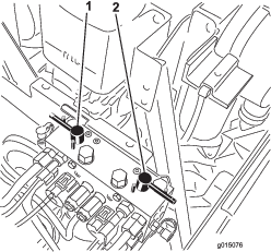
Replacing the Hydraulic Filters
Change the 2 hydraulic filters initially after the first 200 operating hours. Thereafter, change the filters after every 800 operating hours, in normal conditions.
Use Toro replacement filters Part No.94-2621 for the rear (cutting unit) of the machine and 75-1310 for the front (charge) of the machine.
Important: Use of any other filter may void the warranty on some components.
-
Park the machine on a level surface, lower the cutting units, engage the parking brake, shut off the engine, and remove the key.
-
Clean the area around the filter mounting area.
-
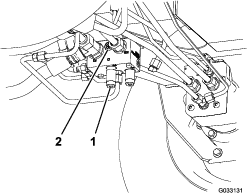
Place a drain pan under the filter and remove the filter (Figure 107 and Figure 108).
-
Lubricate the new filter gasket and fill the filter with hydraulic fluid.
-
Ensure that the filter mounting area is clean.
-
Screw the filter on until the gasket contacts the mounting plate; then tighten the filter an additional 1/2 turn.
-
Start the engine and let it run for about 2 minutes to purge air from the system.
-
Shut off the engine and check for leaks.
Checking the Hydraulic Lines and Hoses
Park the machine on a level surface, lower the cutting units, engage the parking brake, shut off the engine, and remove the key.
Inspect the hydraulic lines and hoses daily for leaks, kinked lines, loose mounting supports, wear, loose fittings, weather deterioration, and chemical deterioration. Make all necessary repairs before operating.
Warning
Hydraulic fluid escaping under pressure can penetrate skin and cause injury.
-
Make sure that all hydraulic fluid hoses and lines are in good condition and all hydraulic connections and fittings are tight before applying pressure to the hydraulic system.
-
Keep your body and hands away from pinhole leaks or nozzles that eject high-pressure hydraulic fluid.
-
Use cardboard or paper to find hydraulic leaks.
-
Safely relieve all pressure in the hydraulic system before performing any work on the hydraulic system.
-
Seek immediate medical attention if fluid is injected into skin.
Cutting Unit Safety
A worn or damaged cutting unit can break, and a piece of a reel or bedknife could be thrown at you or bystanders, resulting in serious personal injury or death.
-
Inspect the cutting units periodically for wear or damage.
-
Use care when checking the cutting units. Wrap the blades or wear gloves, and use caution when servicing the reels and bedknives. Only replace or sharpen the reels and bedknives; never straighten or weld them.
-
On multi-bladed machines, take care as rotating 1 reel can cause other blades to rotate.
Backlapping the Cutting Units
Warning
Contact with the reels or other moving parts can result in personal injury.
-
Keep fingers, hands, and clothing away from the reels or other moving parts.
-
Never attempt to turn the reels by hand or foot while the engine is running.
Note: When backlapping, the front units all operate together, and the rear units operate together.
-
Park the machine on a level surface, lower the cutting units, engage the parking brake, shut off the engine, and move the PTO switch to the OFF position.
-
Unlock and raise the hood to expose the controls.
-
Make initial reel-to-bedknife adjustments appropriate for backlapping on all cutting units which are to be backlapped; refer to the cutting unit Operator's Manual.
-
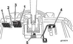
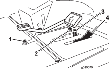
Select either front, rear, or both backlap levers to determine which units to backlap (Figure 109).
-
Start the engine and run at low idle speed.
Danger
Changing the engine speed while backlapping may cause the reels to stall.
-
Never change the engine speed while backlapping.
-
Only backlap at low idle engine speed.
Danger
Contact with the cutting units could cause personal injury.
Be certain that you are clear of the cutting units before proceeding.
-
-
With the mow-speed limiter in the MOW position, move the PTO switch to the ON position.
-
Press the lift switch to start the backlapping operation on the designated reels.
-
Apply lapping compound with a long-handled brush.
Note: Do not use a short-handled brush.
-
If the reels stall or become erratic while backlapping, increase the throttle speed until the reel stabilizes.
-
To make an adjustment to the cutting units while backlapping, turn the reels off by pressing the rear of the lift switch; move the PTO switch to the OFF position and shut off the engine. After completing any adjustments, repeat steps 5 through 9.
-
Repeat the procedure for all cutting units that you want to backlap.
-
When finished, return the backlap levers to the MOW position, lower the hood, and wash all lapping compound off the cutting units. Adjust the cutting unit reel-to-bedknife as needed. Move the cutting unit reel-speed controls to the desired mowing position.
Important: If you do not return the backlap switch to the OFF position after backlapping, the cutting units will not raise or function properly.
Note: Additional instructions and procedures on backlapping are available in the Toro Sharpening Reel and Rotary Mowers Manual, Form No. 80-300SL.
Note: For a better cutting edge, run a file across the front face of the bedknife after lapping. This will remove any burrs or rough edges that may have built up on the cutting edge.