| Maintenance Service Interval | Maintenance Procedure |
|---|---|
| Before each use or daily |
|
Introduction
This machine is a ride-on, rotary-blade lawnmower intended to be used by homeowners in residential applications. It is primarily designed for cutting grass on well-maintained lawns. It is not designed for cutting brush, mowing grass and other growth alongside highways, or for agricultural uses.
Read this information carefully to learn how to operate and maintain your product properly and to avoid injury and product damage. You are responsible for operating the product properly and safely.
You may contact Toro directly at www.Toro.com for product safety and operation training materials, accessory information, help finding a dealer, or to register your product.
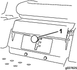
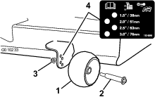
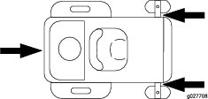
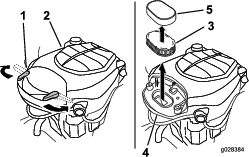
Whenever you need service, genuine Toro parts, or additional information, contact an Authorized Service Dealer or Toro Customer Service and have the model and serial numbers of your product ready. Figure 1 identifies the location of the model and serial numbers on the product. Write the numbers in the space provided.
Write the product model and serial numbers in the space below:
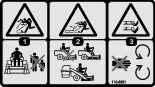
This manual identifies potential hazards and has safety messages identified by the safety alert symbol (Figure 2), which signals a hazard that may cause serious injury or death if you do not follow the recommended precautions.

This manual uses 2 words to highlight information. Important calls attention to special mechanical information and Note emphasizes general information worthy of special attention.
Warning
This product contains a chemical or chemicals known to the State of California to cause cancer, birth defects, or other reproductive harm.
The engine exhaust from this product contains chemicals known to the State of California to cause cancer, birth defects, or other reproductive harm.
Important: This engine is not equipped with a spark arrester muffler. It is a violation of California Public Resource Code Section 4442 to use or operate the engine on any forest-covered, brush-covered, or grass-covered land. Other states or federal areas may have similar laws.
The enclosed Engine Owner's Manual is supplied for information regarding the US Environmental Protection Agency (EPA) and the California Emission Control Regulation of emission systems, maintenance, and warranty. Replacements may be ordered through the engine manufacturer.
For models with stated engine horsepower, the gross horsepower of the engine was laboratory rated by the engine manufacturer in accordance with SAE J1940. As configured to meet safety, emission, and operating requirements, the actual engine horsepower on this class of lawn mower will be significantly lower.
Safety
To reduce the potential for injury, comply with these safety instructions and always pay attention to the safety alert symbol, which means CAUTION, WARNING, or DANGER-"personal safety instruction." Failure to comply with the instruction may result in personal injury or death.
Safe Operating Practices
This product is capable of amputating hands and feet and throwing objects. Always follow all safety instructions to avoid serious injury or death.
The following instructions are adapted from ANSI standard B71.1-2012. All the language within this ANSI standard applies to this machine; however, due to the application of the standard across many different types of products some statements can seem general or misleading. In these instances, Toro has refined the statement to convey the meaning of the standard while better matching the product this Operator's Manual pertains. Safety information in addition to the instructions found in the ANSI standard below can be found in Toro Riding Mower Safety at the end of this section.
General Operation
-
Read, understand, and follow all instructions in the operator's manual and on the machine before starting.
-
Do not place hands or feet near rotating parts or under the machine. Keep clear of the discharge opening at all times.
-
Allow only responsible adults who are familiar with the instructions to operate the machine.
-
Clear the area of objects such as rocks, toys, wire, etc., which could be picked up and thrown by the blade.
-
Be sure the area is clear of other people before mowing. Stop the machine if anyone enters the area.
-
Never carry passengers.
-
Do not mow in reverse unless absolutely necessary. Always look down and behind before and while backing up.
-
Be aware of the mower discharge direction and do not point it at anyone. Avoid discharging material against a wall or obstruction. Material may ricochet back toward the operator. Stop the blade(s) when crossing gravel surfaces.
-
Do not operate the machine without deflector, discharge cover or entire grass collection system in place and working.
-
Be alert, slow down and use caution when making turns. Look behind and to the side before changing directions.
-
Never leave a running machine unattended. Always turn off blades, set parking brake, stop engine, and remove key before dismounting.
-
Turn off blades when not mowing. Stop the engine, wait for all parts to come to a complete stop and remove the key before cleaning the machine, removing the grass catcher or unclogging the discharge chute.
-
Operate the machine only in daylight or good artificial light.
-
Do not operate the machine while under the influence of alcohol or drugs.
-
Watch for traffic when operating near or crossing roadways.
-
Use extra care when loading or unloading the machine into a trailer or truck.
-
Always wear eye protection when operating the mower.
-
Data indicates that operators, age 60 years and above, are involved in a large percentage of riding mower-related injuries. Operators should evaluate their ability to operate the riding mower safely enough to protect themselves and others from serious injury.
-
Always follow the recommendations for any application of counterweights.
-
Lightning can cause severe injury or death. If lightning is seen or thunder is heard in the area, do not operate the machine; seek shelter.
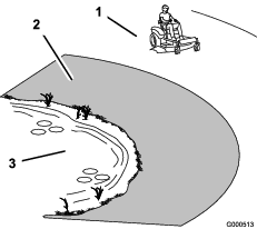
Slope Operation
Slopes are a major factor related to loss of control and tip-over accidents, which can result in severe injury or death. Operation on all slopes requires extra caution. If you cannot back up the slope or if you feel uneasy on it, do not mow it.
-
Do not mow slopes greater than 15 degrees.
-
Watch for ditches, holes, rocks, dips, and rises that change the operating angle, as rough terrain could overturn the machine.
-
Choose a low ground speed so you will not have to stop while operating on a slope.
-
Do not mow slopes when grass is wet. Slippery conditions reduce traction and could cause sliding and loss of control.
-
Always keep the drive wheels engaged when going down slopes.
-
Reduce speed and use extreme caution on slopes.
-
Do not make sudden turns or rapid speed changes.
-
Remove or mark obstacles such as rocks, tree limbs, etc. from the mowing area. Tall grass can hide obstacles.
-
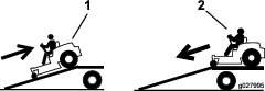
Avoid sudden starts when mowing uphill because the mower may tip backwards.
-
Be aware that loss of traction may occur going downhill. Weight transfer to the front wheels may cause drive wheels to slip and cause loss of braking and steering.
-
Always avoid sudden starting or stopping on a slope. If tires lose traction, stop the machine, disengage the blades and proceed slowly off the slope.
-
Use extreme care with grass catchers or other attachments. These can change the stability of the machine and cause loss of control.
-
Do not try to stabilize the machine by putting your foot on the ground.
-
Do not mow near drop-offs, ditches, steep banks or water. Wheels dropping over edges can cause rollovers, which may result in serious injury, death or drowning.
-
Use a walk behind mower and/or a hand trimmer near drop-offs, ditches, steep banks or water.
Children
Tragic accidents can occur if the operator is not alert to the presence of children. Children are often attracted to the machine and the mowing activity. Never assume that children will remain where you last saw them.
-
Keep children out of the mowing area and under the watchful care of another responsible adult, not the operator.
-
Be alert and turn the machine off if children enter the area.
-
Before and while backing or changing direction, look behind, down, and side-to-side for small children.
-
Never carry children, even with the blades off. They may fall off and be seriously injured or interfere with safe machine operation.
-
Children who have been given rides in the past may suddenly appear in the mowing area for another ride and be run over or backed over by the mower.
-
Never allow children to operate the machine.
-
Use extra care when approaching blind corners, shrubs, trees, the end of a fence or other objects that may obscure vision.
Towing Safety
-
Do not attach towed equipment except at the hitch point.
-
Follow the attachment manufacturer's recommendation for weight limits for towed equipment and towing on slopes. Towed weight must not exceed the weight of the machine, operator, and ballast. Use counterweights or wheel weights as described in the attachment, or in the pulling machine Operator’s Manual.
-
Never allow children or others in or on towed equipment.
-
On slopes, the weight of the towed equipment may cause loss of traction, increased risk of rollover, and loss of control. Reduce the towed weight and slow down.
-
Stopping distance increases with the weight of the towed load. Travel slowly and allow extra distance to stop.
-
Make wide turns to keep the attachment clear of the machine.
Service
Safe Handling of Gasoline
To avoid personal injury or property damage, use extra care when handling gasoline and other fuels. They are flammable and the vapors are explosive.
-
Extinguish all cigarettes, cigars, pipes and other sources of ignition.
-
Use only an approved container.
-
Never remove the gas cap or add fuel when the engine is running. Allow the engine to cool before refueling.
-
Never refuel the machine indoors.
-
Never store the machine or fuel container inside where there is an open flame, such as near a water heater or furnace.
-
Never fill containers inside a vehicle or on a truck or trailer with a plastic liner. Always place containers on the ground away from your vehicle before filling.
-
Remove gas-powered equipment from the truck or trailer and refuel it on the ground. If this is not possible, then refuel such equipment with a portable container, rather than from a gasoline dispenser nozzle.
-
Keep the nozzle in contact with the rim of the fuel tank or container opening at all times until the fueling is complete. Do not use a nozzle lock-open device.
-
If fuel is spilled on clothing, change clothing immediately.
-
Never overfill the fuel tank. Replace gas cap and tighten securely.
General Service
-
Never operate a machine inside a closed area. Engine exhaust contains carbon monoxide, which is an odorless, deadly poison that can kill you.
-
Keep nuts and bolts tight, especially the blade attachment bolts. Keep equipment in good condition.
-
Never interfere with the intended function of a safety device or to reduce the protection provided by a safety device. Check their proper operation regularly.
-
Keep the machine free of grass, leaves, or other debris build-up. Clean up oil or fuel spillage fuel soaked debris. Allow the machine to cool before storing.
-
Stop and inspect the equipment if you strike an object. Repair, if necessary, before restarting.
-
Never make any adjustments or repairs with the engine running.
-
Grass catcher components are subject to wear, damage and deterioration, which could expose moving parts or allow objects to be thrown. Frequently check components and replace with manufacturers' recommended parts, when necessary.
-
Mower blades are sharp and can cut. Wrap the blade(s) or wear thickly-padded gloves, and use extra caution when servicing them.
-
Check for proper brake operation frequently. Adjust and service as required.
-
Maintain or replace safety and instruction decals as necessary.
-
Use only genuine Toro replacement parts to ensure that original standards are maintained.
Toro Riding Mower Safety
The following list contains safety information specific to Toro products or other safety information that you must know that may not be included in the ANSI standards.
-
Stop the engine, move the motion control levers to neutral and outward to the park position, disengage the blade control switch, remove key before and disconnect spark plug wire(s) performing any service, repairs, maintenance or adjustments.
-
Keep hands, feet, hair, and loose clothing away from attachment discharge area, underside of mower and any moving parts while engine is running.
-
Do not touch equipment or attachment parts which may be hot from operation. Allow to cool before attempting to maintain, adjust or service.
-
Battery acid is poisonous and can cause burns. Avoid contact with skin, eyes, and clothing. Protect your face, eyes, and clothing when working with a battery.
-
Battery gases can explode. Keep cigarettes, sparks and flames away from battery.
-
Use only Toro approved attachments. Warranty may be voided if used with unapproved attachments.
-
If loading the machine onto a trailer or truck, use a single, full-width ramp only. The ramp angle should not exceed 15 degrees.
-
The use of protective equipment for eyes, ears, hands, feet, and head is recommended.
Slope Indicator
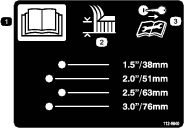
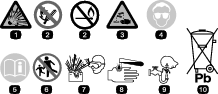
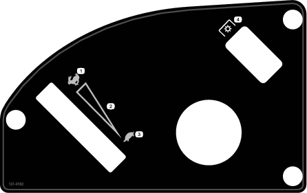
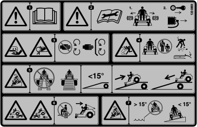
Safety and Instructional Decals
 |
Safety decals and instructions are easily visible to the operator and are located near any area of potential danger. Replace any decal that is damaged or lost. |


Product Overview
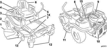
Become familiar with all of the controls in Figure 4 and Figure 5 before you start the engine and operate the machine.
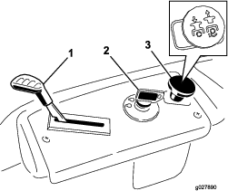
Ignition Switch
The ignition switch has 3 positions, Off, Run, and Start. The key will turn to Start and move back to Run upon release. Turning the key to the Off position will stop the engine; however, always remove the key when leaving the machine to prevent someone from accidentally starting the engine (Figure 5).
Throttle Control
The throttle controls the engine speed and it has a continuous variable setting from Slow to Fast ().
Blade-Control Switch (Power Take-off)
The blade-control switch, represented by a power take-off (PTO) symbol, engages and disengages power to the mower blades (Figure 5).
Motion Control Levers and Parking Brake Position
The motion control levers are speed sensitive controls of independent wheel motors. Moving a lever forward or backward turns the wheel on the same side forward or in reverse; wheel speed is proportional to the amount the lever is moved. Move the control levers outward from the center to the park position and exit the machine (Figure 15). Always position the motion control levers into the park position when you stop the machine or leave it unattended.
Smart Speed
The Smart Speed™ Control-System lever, located below the operating position, gives the operator a choice to drive the machine at 3 speed ranges—trim, tow, and mow(Figure 6).
Fuel Window
The fuel window located on the left hand side of the machine can be used to verify the presence of gasoline in the tank (Figure 7).
Height-of-Cut Lever
The height of cut lever allows the operator to lower and raise the deck from the seated position. When the lever is moved up, toward the operator the deck is raised from the ground and when moved down, away from the operator it is lowered toward the ground. Only adjust the height of cut while machine is not moving (Figure 4).
Hour Meter
The hour meter records the number of hours when the operator is in the seat and the ignition switch is in the ON position (Figure 8).
Operation
Note: Determine the left and right sides of the machine from the normal operating position.
Adding Fuel
-
For best results, use only clean, fresh (less than 30 days old), unleaded gasoline with an octane rating of 87 or higher ((R+M)/2 rating method).
-
Ethanol: Gasoline with up to 10% ethanol (gasohol) or 15% MTBE (methyl tertiary butyl ether) by volume is acceptable. Ethanol and MTBE are not the same. Gasoline with 15% ethanol (E15) by volume is not approved for use. Never use gasoline that contains more than 10% ethanol by volume, such as E15 (contains 15% ethanol), E20 (contains 20% ethanol), or E85 (contains up to 85% ethanol ). Using unapproved gasoline may cause performance problems and/or engine damage which may not be covered under warranty.
-
Do not use gasoline containing methanol.
-
Do not store fuel either in the fuel tank or fuel containers over the winter unless a fuel stabilizer is used.
-
Do not add oil to gasoline.
Danger
In certain conditions, gasoline is extremely flammable and highly explosive. A fire or explosion from gasoline can burn you and others and can damage property.
-
Fill the fuel tank outdoors, in an open area, when the engine is cold. Wipe up any gasoline that spills.
-
Never fill the fuel tank inside an enclosed trailer.
-
Do not fill the fuel tank completely full. Add gasoline to the fuel tank until the fuel reaches the base of the filler neck. This empty space in the tank allows gasoline to expand.
-
Never smoke when handling gasoline, and stay away from an open flame or where gasoline fumes may be ignited by a spark.
-
Store gasoline in an approved container and keep it out of the reach of children. Never buy more than a 30-day supply of gasoline.
-
Do not operate without entire exhaust system in place and in proper working condition.
Danger
In certain conditions during fueling, static electricity can be released causing a spark which can ignite the gasoline vapors. A fire or explosion from gasoline can burn you and others and can damage property.
-
Always place gasoline containers on the ground away from your vehicle before filling.
-
Do not fill gasoline containers inside a vehicle or on a truck or trailer bed because interior carpets or plastic truck bed liners may insulate the container and slow the loss of any static charge.
-
When practical, remove gas-powered equipment from the truck or trailer and refuel the equipment with its wheels on the ground.
-
If this is not possible, then refuel such equipment on a truck or trailer from a portable container, rather than from a gasoline dispenser nozzle.
-
If a gasoline dispenser nozzle must be used, keep the nozzle in contact with the rim of the fuel tank or container opening at all times until fueling is complete.
Warning
Gasoline is harmful or fatal if swallowed. Long-term exposure to vapors can cause serious injury and illness.
-
Avoid prolonged breathing of vapors.
-
Keep face away from nozzle and gas tank or conditioner opening.
-
Keep gas away from eyes and skin.
Using Stabilizer/Conditioner
Use a fuel stabilizer/conditioner in the machine to provide the following benefits:
-
Keeps gasoline fresh during storage of 90 days or less. For longer storage it is recommended that the fuel tank be drained.
-
Cleans the engine while it runs
-
Eliminates gum-like varnish buildup in the fuel system, which causes hard starting
Important: Do not use fuel additives containing methanol or ethanol.
Add the correct amount of gas stabilizer/conditioner to the gas.
Note: A fuel stabilizer/conditioner is most effective when mixed with fresh gasoline. To minimize the chance of varnish deposits in the fuel system, use fuel stabilizer at all times.
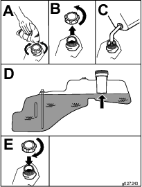
Filling the Fuel Tank
Note: Make sure the engine is shut off and the motion controls are in the park position.
Note: You can use the fuel window to verify the presence of gasoline before filling the tank (Figure 9).
Important: Do not overfill fuel tank. Fill the fuel tank to the bottom of the filler neck. The empty space in the tank allows the fuel to expand. Overfilling may result in fuel leakage or damage to the engine or emissions system.
Checking the Engine-Oil Level
Before you start the engine and use the machine, check the oil level in the engine crankcase; refer to Checking the Engine-Oil Level.
Breaking in a New Machine
New engines take time to develop full power. Mower decks and drive systems have higher friction when new, placing additional load on the engine. Allow 40 to 50 hours of break-in time for new machines to develop full power and best performance.
Think Safety First
Operating Safety
Please carefully read all of the safety instructions and decals in the safety section. Knowing this information could help you, your family, pets or bystanders avoid injury.
Danger
Mowing on wet grass or steep slopes can cause sliding and loss of control.
Wheels dropping over edges can cause rollovers, which may result in serious injury, death or drowning.
A loss of traction is a loss of steering control.
To avoid loss of control and possibility of rollover:
-
Do not mow near drop-offs or near water.
-
Do not mow slopes greater than 15 degrees.
-
Reduce speed and use extreme caution on slopes.
-
When mowing slopes, gradually work from lower to higher areas on the incline.
-
Avoid sudden turns or rapid speed changes.
-
Turn up, into an incline when changing directions on slopes. Turning down the slope reduces traction.
-
Attachments change the handling characteristics of the machine. Use extra caution when using attachments with the machine.
Caution
This machine produces sound levels in excess of 85 dBA at the operators ear and can cause hearing loss through extended periods of exposure.
Wear hearing protection when operating this machine.

Understanding the Safety Interlock System
Warning
If safety interlock switches are disconnected or damaged the machine could operate unexpectedly causing personal injury.
-
Do not tamper with the interlock switches.
-
Check the operation of the interlock switches daily and replace any damaged switches before operating the machine.
The safety interlock system is designed to prevent the engine from starting unless:
-
The blades are disengaged.
-
The motion control levers are in the park position.
The safety interlock system also is designed to stop the engine whenever the control levers are out of the park position and you rise from the seat.
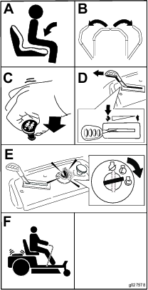
Testing the Safety Interlock System
Test the safety interlock system before you use the machine each time. If the safety system does not operate as described below, have an Authorized Service Dealer repair the safety system immediately.
-
While sitting on the seat, with the control levers in park position, and move the blade control switch to On. Try starting the engine; the engine should not crank.
-
While sitting on the seat, move the blade control switch to Off. Move either motion control lever to the center, unlocked position. Try starting the engine; the engine should not crank. Repeat with the other motion control lever.
-
While sitting on the seat, move the blade control switch to Off, and lock the motion control levers in the park position. Start the engine. While the engine is running, engage the blade control switch, and rise slightly from the seat; the engine should stop.
-
While sitting on the seat, move the blade control switch to Off, and lock the motion control levers in the park position. Start the engine. While the engine is running, move the motion control levers to the center, unlocked position, engage the blade control switch, and rise slightly from the seat; the engine should stop.
Starting the Engine
Important: Do not engage the starter for more than 10 seconds at a time. If the engine fails to start, allow a 60 second cool-down period between attempts. Failure to follow these instructions can damage the starter motor.
Operating the Blades
The blade control switch, represented by a power take-off (PTO) symbol, engages and disengages power to the mower blades. This switch controls power to any attachments that draw power from the engine, including the mower deck and cutting blades.
Engaging the Blades
Important: Do not engage the blades when parked in tall grass. Belt or clutch damage can occur.
Note: Always engage the blades with the throttle in the Fast position.
Disengaging the Blades
Stopping the Engine
-
Disengage the blades by moving the blade control switch to Off.
-
Move the throttle lever to between the half and full throttle position.
-
Turn the ignition key to Off and remove the key.
Driving
Driving the machine benefits from an understanding of what zero turn radius mower means. The drive wheels turn independently, powered by hydraulic motors on each axle; hence one side can turn in reverse while the other turns forward causing the machine to spin rather than turn. This vastly improves the machine maneuverability but may require some adjustment if the operator is unfamiliar.
Warning
The machine can spin very rapidly. The operator may lose control of the machine and cause personal injury or damage to the machine.
-
Use caution when making turns.
-
Slow the machine down before making sharp turns.
The throttle control regulates the engine speed as measured in rpm (revolutions per minute). Placing the throttle control in the Fast position can be best for performance. For most applications, operating in the full throttle position is desirable.
Using the Smart Speed
The Smart Speed TM Control-System lever, located below the operating position (Figure 16), gives the operator a choice to drive the machine at 3 ground speed ranges—trim, tow, and mow.
To change speeds, do the following:
-
Move the motion control levers to neutral and outward to the park position.
-
Disengage the blade control switch
-
Adjust the lever to the desired position.
The following are only recommendations for use. Adjustments will vary by grass type, moisture content, and the height of the grass.
| Suggested uses: | Trim | Tow | Mow |
| Parking | X | ||
| Heavy, wet grass | X | ||
| Training | X | ||
| Bagging | X | ||
| Mulching | X | ||
| Normal mowing | X | ||
| Transport | X |
Trim
This is the lowest speed. The suggested uses for this speed are as follows:
-
Parking
-
Heavy, wet grass mowing conditions
-
Training
Tow
This is the medium speed. The suggested uses for this speed are as follows:
-
Bagging
-
Mulching
Mow
This is the fastest speed. The suggested uses for this speed are as follows:
-
Normal mowing
-
Transporting the machine
Forward
-
Move the levers to the center, unlocked position.
-
To go forward, slowly push the motion control levers forward (Figure 17).
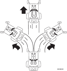
To go straight, apply equal pressure to both motion control levers (Figure 17).
To turn, release pressure on the motion control lever toward the direction you want to turn (Figure 17).
The farther you move the motion control levers in either direction, the faster the machine will move in that direction.
To stop, pull the motion control levers to neutral.
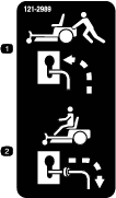
Backward
Note: Always use caution when backing up and turning.
-
Move the levers to the center, unlocked position.
-
To go backward, look behind you and down as you slowly pull the motion control levers rearward (Figure 18).
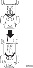
To go straight, apply equal pressure to both motion control levers (Figure 18).
To turn, release the pressure on the motion control lever toward the direction you want to turn.
To stop, push the motion control levers to neutral.
Stopping the Machine
To stop the machine, move the motion control levers to neutral and outward to the park position, disengage the blade control switch, ensure the throttle between the half and full throttle position, and turn the ignition key to Off. Remember to remove the key from the ignition switch.
Warning
Children or bystanders may be injured if they move or attempt to operate the mower while it is unattended.
Always remove the ignition key and move the motion control levers outward to the park position when leaving the machine unattended, even if just for a few minutes.
Adjusting the Height of Cut
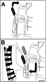
Adjusting the Anti-Scalp Rollers
Whenever you change the height-of-cut, adjust the height of the anti-scalp rollers.
Note: Adjust the anti-scalp rollers so the rollers do not touch the ground in normal, flat mowing areas.
-
Disengage the blade control switch (PTO), move the motion control levers to the neutral lock position and set the parking brake.
-
Stop the engine, remove the key, and wait for all moving parts to stop before leaving the operating position.
-
Adjust the anti-scalp rollers as shown in Figure 20 to match the closest height-of-cut position.
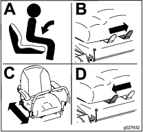
Positioning the Seat
The seat can move forward and backward. Position the seat where you have the best control of the machine and are most comfortable.
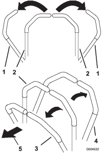
Adjusting the Motion Control Levers
Adjusting the Height
The motion control levers can be adjusted higher or lower for maximum operator comfort (Figure 22).
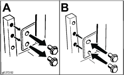
Adjusting the Tilt
The motion control levers can be tilted fore or aft for maximum operator comfort.
-
Loosen the upper bolt holding the control lever to the control arm shaft.
-
Loosen the lower bolt just enough to pivot the control lever fore or aft (Figure 22). Tighten both bolts to secure the control in the new position.
-
Repeat the adjustment for the opposite control lever.
Pushing the Machine by Hand
Important: Always push the machine by hand. Never tow the machine because damage may occur.
This machine has an electric brake mechanism and to push the machine the ignition key needs to be in the Run position. The battery needs to be charged and functioning for the electric brake to be disengage.
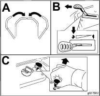
Pushing the Machine
-
Park the machine on a level surface and disengage the blade control switch.
-
Move the motion control levers outward to park position, stop the engine, and wait for all moving parts to stop before leaving the operating position.
-
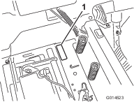
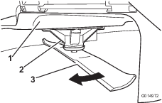
Locate the bypass levers on the frame on both sides of the engine.
-
Move the bypass levers forward through the key hole and down to lock them in place as shown in Figure 23 . Ensure this is done for each lever.
-
Move the motion control levers inward to the neutral position and turn the ignition key to the run position. Do not start the machine.
The machine is now able to be pushed by hand.
-
When finished, ensure the key has been returned to the Stop position to avoid draining the battery charge.
If the machine fails to move the electric brake may still be engaged. If necessary the electric brake can be released manually. Refer to the Releasing the Electric Brake.
Operating the Machine
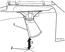
Move the bypass levers rearward through the key hole and down to lock them in place as shown in Figure 23. Ensure this is done for each lever.
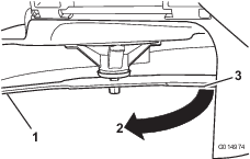
Grass Deflector
The mower has a hinged grass deflector that disperses clippings to the side and down toward the turf.
Danger
Without the grass deflector, discharge cover, or complete grass catcher assembly mounted in place, you and others are exposed to blade contact and thrown debris. Contact with rotating mower blade(s) and thrown debris will cause injury or death.
-
Never remove the grass deflector from the mower because the grass deflector routes material down toward the turf. If the grass deflector is ever damaged, replace it immediately.
-
Never put your hands or feet under the mower.
-
Never try to clear discharge area or mower blades unless you move the blade control switch to Off and rotate the ignition key to Off. Also remove the key and pull the wire off the spark plug(s).
Transporting the Machine
Use a heavy-duty trailer or truck to transport the machine. Ensure that the trailer or truck has all necessary brakes, lighting, and marking as required by law. Please carefully read all the safety instructions. Knowing this information could help you, your family, pets, or bystanders avoid injury.
Warning
Driving on the street or roadway without turn signals, lights, reflective markings, or a slow moving vehicle emblem is dangerous and can lead to accidents causing personal injury.
Do not drive machine on a public street or roadway.
To transport the machine:
-
If using a trailer, connect it to the towing vehicle and connect the safety chains.
-
If applicable, connect the trailer brakes.
-
Load the machine onto the trailer or truck.
-
Stop the engine, remove the key, set the brake, and close the fuel valve.
-
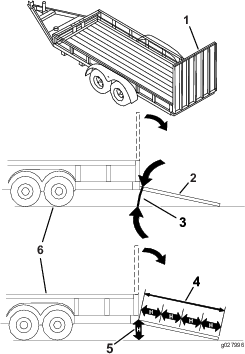
Tie down the machine near the front caster wheels and the rear bumper (Figure 24).
Loading the Machine
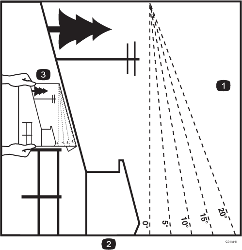
Use extreme caution when loading or unloading machines onto a trailer or a truck. Use a full-width ramp that is wider than the machine for this procedure. Back up ramps and drive forward down ramps (Figure 25).
Important: Do not use narrow individual ramps for each side of the machine.
Ensure the ramp is long enough so that the angle with the ground does not exceed 15 degrees (Figure 26). On flat ground, this requires a ramp to be at least four times (4X) as long as the height of the trailer or truck bed to the ground. A steeper angle may cause mower components to get caught as the unit moves from the ramp to the trailer or truck. Steeper angles may also cause the machine to tip or lose control. If loading on or near a slope, position the trailer or truck so that it is on the down side of the slope and the ramp extends up the slope. This will minimize the ramp angle.
Warning
Loading a machine onto a trailer or truck increases the possibility of tip-over and could cause serious injury or death.
-
Use extreme caution when operating a machine on a ramp.
-
Use only a full-width ramp; do not use individual ramps for each side of the machine.
-
Do not exceed a 15-degree angle between the ramp and the ground or between the ramp and the trailer or truck.
-
Ensure the length of ramp is at least four times (4X) as long as the height of the trailer or truck bed to the ground. This will ensure that ramp angle does not exceed 15 degrees on flat ground.
-
Back up ramps and drive forward down ramps.
-
Avoid sudden acceleration or deceleration while driving the machine on a ramp as this could cause a loss of control or a tip-over situation.
Operating Tips
Fast Throttle Setting
For best mowing and maximum air circulation, operate the engine at the Fast position. Air is required to thoroughly cut grass clippings, so do not set the height-of-cut so low as to totally surround the mower by uncut grass. Always try to have one side of the mower free from uncut grass, which allows air to be drawn into the mower.
Using the Smart Speed
The Smart Speed™ Control System lever, located below the operating position, gives the operator a choice to drive the machine at 3 speed ranges, trim, tow, and mow. An operator can benefit from the trim speed setting when maneuvering the machine in tight spaces or operating around delicate landscapes. The trim setting can also be used to operate the machine at a high throttle setting and blade speed while still being able to reduce ground speed to increase quality of cut.
Cutting a Lawn for the First Time
Cut grass slightly longer than normal to ensure that the cutting height of the mower does not scalp any uneven ground. However, the cutting height used in the past is generally the best one to use. When cutting grass longer than six inches tall, you may want to cut the lawn twice to ensure an acceptable quality of cut.
Cut 1/3 of the Grass Blade
It is best to cut only about 1/3 of the grass blade. Cutting more than that is not recommended unless grass is sparse, or it is late fall when grass grows more slowly.
Alternating the Direction
Alternate mowing direction to keep the grass standing straight. This also helps disperse clippings which enhances decomposition and fertilization.
Mow at Correct Intervals
Normally, mow every four days. But remember, grass grows at different rates at different times. So to maintain the same cutting height, which is a good practice, mow more often in early spring. As the grass growth rate slows in mid summer, mow less frequently. If you cannot mow for an extended period, first mow at a high cutting height; then mow again two days later at a lower height setting.
Avoid Cutting Too Low
If the cutting width of the mower is wider than the mower you previously used, raise the cutting height to ensure that uneven turf is not cut too short.
Long Grass
If the grass is ever allowed to grow slightly longer than normal, or if it contains a high degree of moisture, raise the cutting height higher than usual and cut the grass at this setting. Then cut the grass again using the lower, normal setting.
When Stopping
If you must stop the forward motion of the machine, a clump of grass clippings may drop onto your lawn. To avoid this, move onto a previously cut area with the blades engaged.
Keep the Underside of the Mower Clean
Clean clippings and dirt from the underside of the mower after each use. If grass and dirt build up inside the mower, cutting quality will eventually become unsatisfactory.
Blade Maintenance
Maintain a sharp blade throughout the cutting season because a sharp blade cuts cleanly without tearing or shredding the grass blades. Tearing and shredding turns grass brown at the edges, which slows growth and increases the chance of disease. Check the cutter blades daily for sharpness, and for any wear or damage. File down any nicks and sharpen the blades as necessary. If a blade is damaged or worn, replace it immediately with a genuine Toro replacement blade.
Maintenance
Note: Determine the left and right sides of the machine from the normal operating position.
Recommended Maintenance Schedule(s)
| Maintenance Service Interval | Maintenance Procedure |
|---|---|
| After the first 50 hours |
|
| Before each use or daily |
|
| After each use |
|
| Every 25 hours |
|
| Every 50 hours |
|
| Every 100 hours |
|
| Every 200 hours |
|
| Every 400 hours |
|
| Every 500 hours |
|
| Before storage |
|
Important: Refer to your engine operator's manual for additional maintenance procedures.
Caution
If you leave the key in the ignition switch, someone could accidently start the engine and seriously injure you or other bystanders.
Remove the key from the ignition and disconnect the wire from the spark plug before you do any maintenance. Set the wire aside so that it does not accidentally contact the spark plug.
Pre-Maintenance Procedures
Raising the Seat
Make sure the motion control levers are locked in the park position. Lift the seat forward.
The following components can be accessed by raising the seat:
-
Serial plate
-
Service decal
-
Seat adjustment bolts
-
Fuel filter
-
Battery and battery cables
Lubrication
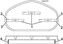
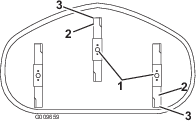
Greasing the Bearings
| Maintenance Service Interval | Maintenance Procedure |
|---|---|
| Every 25 hours |
|
Grease Type: No. 2 general-purpose, lithium-based grease
-
Park the machine on a level surface and disengage the blade control switch.
-
Move the motion control levers outward to the park position, stop the engine, remove the key, and wait for all moving parts to stop before leaving the operating position.
-
Clean the grease fittings (Figure 27 and Figure 28) with a rag. Make sure to scrape any paint off the front of the fitting(s).
-
Connect a grease gun to each fitting (Figure 27 and Figure 28). Pump grease into the fittings until grease begins to ooze out of the bearings.
-
Wipe up any excess grease.
Engine Maintenance
Servicing the Air Cleaner
| Maintenance Service Interval | Maintenance Procedure |
|---|---|
| Before each use or daily |
|
| Every 25 hours |
|
| Every 50 hours |
|
| Every 100 hours |
|
This engine is equipped with a replaceable, high density paper air-cleaner element. Check the air cleaner daily or before starting the engine. Check for a buildup of dirt and debris around the air-cleaner system. Keep this area clean. Also, check for loose or damaged components. Replace all bent or damaged air-cleaner components.
Note: Operating the engine with loose or damaged air-cleaner components could allow unfiltered air into the engine, causing premature wear and failure.
Note: Service the air cleaner more often under extremely dusty, dirty conditions.
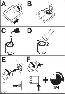
-
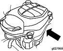
Rotate the latches outward.
-
Remove the cover to access the air-cleaner element (Figure 29).
-
Remove the precleaner and paper element.
-
Remove the precleaner from the paper element, and gently tap the paper element to dislodge dirt
Note: Do not wash the paper element or use pressurized air, as this will damage the element.
Note: Replace a dirty, bent, or damaged element. Handle the new element carefully; do not use if the sealing surfaces are bent or damaged.
-
Replace or wash the precleaner in warm water with detergent, rinse, and air dry.
-
Lightly oil the precleaner with new engine oil and squeeze out excess oil.
-
Clean the air-cleaner base as required, and check the condition.
-
Install the precleaner over the paper element.
-
Install the precleaner and paper element onto the air-cleaner base.
-
Install the cover, and secure it with the latches (Figure 29).
Servicing the Engine Oil
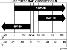
Oil Type: Detergent oil (API service SJ or higher)
Crankcase Capacity: 1.9 L (64 oz) when the filter is changed
Viscosity: See the table below.
Checking the Engine-Oil Level
| Maintenance Service Interval | Maintenance Procedure |
|---|---|
| Before each use or daily |
|
-
Park the machine on a level surface, disengage the blade-control switch, stop the engine, and remove the key.
-
Make sure the engine is stopped, level, and is cool, so the oil has time to drain into the sump.
-
Check the engine-oil level (Figure 31).
Changing the Engine Oil and the Engine-Oil Filter
| Maintenance Service Interval | Maintenance Procedure |
|---|---|
| Every 100 hours |
|
Note: The drain plug is attached to the drain hose.
Note: Dispose of the used oil at a recycling center.
Fill with oil as specified in the “Viscosity Grades” table (Figure 30).
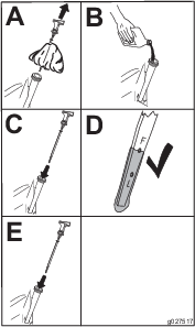
-
Park the machine, so that the drain side is slightly lower than the opposite side, to ensure that the oil drains completely.
-
Disengage the blade-control switch and move the motion controls outward to the park position.
-
Stop the engine, remove the key, and wait for all moving parts to stop before leaving the operating position.
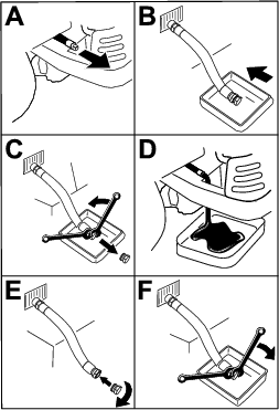
-
Torque the plug to 14 N-m (125 in-lb).
-
Slowly pour approximately 80% of the specified oil into the filler tube (Figure 34).
Servicing the Spark Plug
| Maintenance Service Interval | Maintenance Procedure |
|---|---|
| Every 200 hours |
|
| Every 500 hours |
|
The spark plug is RFI compliant. Equivalent alternate brand plugs can also be used.
Type: Champion XC12YC (or equivalent)
Air Gap: 0.76 mm (0.03 inch)
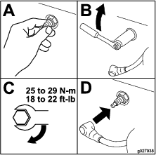
Removing the Spark Plug
-
Disengage the blade-control switch, move the motion controls outward to the park position, stop the engine, and remove the key.
-
Before removing the spark plug(s), clean the area around the base of the plug to keep dirt and debris out of the engine.
-
Remove the spark plug (Figure 35).
Checking the Spark Plug
Important: Do not clean the spark plug(s). Always replace the spark plug(s) when it has: a black coating, worn electrodes, an oily film, or cracks.
Note: If you see light brown or gray on the insulator, the engine is operating properly. A black coating on the insulator usually means the air cleaner is dirty.
Set the gap to 0.76 mm (0.030 inch).
Installing the Spark Plug
Tighten the spark plug to 25 to 29 N-m (18 to 22 ft-lb).
Cleaning the Blower Housing
| Maintenance Service Interval | Maintenance Procedure |
|---|---|
| Every 100 hours |
|
To ensure proper cooling, make sure the grass screen, cooling fins, and other external surfaces of the engine are kept clean at all times.
Annually, or every 100 hours of operation (more often under extremely dusty, dirty conditions), remove the blower housing, and any other cooling shrouds. Clean the cooling fins and external surfaces as necessary. Make sure the cooling shrouds are installed. Torque the blower housing screws to 7.5 N-m (5.5 ft-lb).
Important: Operating the engine with a blocked grass screen, dirty or plugged cooling fins, and/or cooling shrouds removed, will cause engine damage due to overheating.
Fuel System Maintenance
Danger
In certain conditions, gasoline is extremely flammable and highly explosive. A fire or explosion from gasoline can burn you and others and can damage property.
-
Perform any fuel related maintenance when the engine is cold. Do this outdoors in an open area. Wipe up any gasoline that spills.
-
Never smoke when draining gasoline, and stay away from an open flame or where a spark may ignite the gasoline fumes.
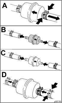
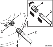
Replacing the In-Line Fuel Filter
| Maintenance Service Interval | Maintenance Procedure |
|---|---|
| Every 100 hours |
|
Never install a dirty filter if it is removed from the fuel line.
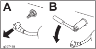
-
Park the machine on a level surface and disengage the blade-control switch.
-
Move the motion-control levers outward to the park position, stop the engine, remove the key, and wait for all moving parts to stop before leaving the operating position.
-
Replace the in-line filter (Figure 38).
Electrical System Maintenance
Warning
Battery posts, terminals, and related accessories contain lead and lead compounds, chemicals known to the State of California to cause cancer and reproductive harm. Wash hands after handling.
Charging the Battery
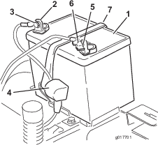
Removing the Battery
Warning
Battery terminals or metal tools could short against metal machine components causing sparks. Sparks can cause the battery gasses to explode, resulting in personal injury.
-
When removing or installing the battery, do not allow the battery terminals to touch any metal parts of the machine.
-
Do not allow metal tools to short between the battery terminals and metal parts of the machine.
-
Park the machine on a level surface and disengage the blade control switch.
-
Move the motion control levers outward to the park position, stop the engine, remove the key, and wait for all moving parts to stop before leaving the operating position.
-
Raise the seat to access the battery.
-
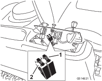
Disconnect the negative (black) ground cable from the battery post (Figure 39). Retain all fasteners.
Warning
Incorrect battery cable routing could damage the machine and cables causing sparks. Sparks can cause the battery gasses to explode, resulting in personal injury.
-
Always disconnect the negative (black) battery cable before disconnecting the positive (red) cable.
-
Always connect the positive (red) battery cable before connecting the negative (black) cable.
-
-
Slide the rubber cover up the positive (red) cable. Disconnect the positive (red) cable from the battery post (Figure 39). Retain all fasteners.
-
Remove the battery hold-down (Figure 39) and lift the battery from the battery tray.
Charging the Battery
| Maintenance Service Interval | Maintenance Procedure |
|---|---|
| Before storage |
|
-
Remove the battery from the chassis; refer to Removing the Battery.
-
Charge the battery for a minimum of 1 hour at 6 to 10 amps. Do not overcharge the battery.
-
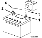
When the battery is fully charged, unplug the charger from the electrical outlet, then disconnect the charger leads from the battery posts (Figure 40).
Installing the Battery
-
Position the battery in the tray (Figure 39).
-
Install the positive (red) battery cable to the positive (+) battery terminal using the fasteners removed previously.
-
Install the negative battery cable to the negative (-) battery terminal using the fasteners removed previously.
-
Slide the red terminal boot onto the positive (red) battery post.
-
Secure the battery with the hold-down (Figure 39).
-
Lower the seat.
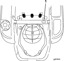
Servicing the Fuses
The electrical system is protected by fuses. It requires no maintenance; however, if a fuse blows, check the component/circuit for a malfunction or short.
Fuse:
-
Main F1-30 amp, blade-type
-
Charge Circuit F2-25 amp, blade-type
-
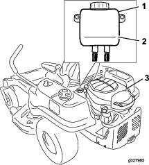
Remove the screws securing the control panel to the machine. Retain all fasteners
-
Lift the control pane up to access the main wiring harness and fuse block (Figure 41).
-
To replace a fuse, pull out on the fuse to remove it (Figure 41).
-
Return the control panel to its original position. Use the screws removed previously to secure the panel to the machine.
Drive System Maintenance
Checking the Tire Pressure
| Maintenance Service Interval | Maintenance Procedure |
|---|---|
| Every 25 hours |
|
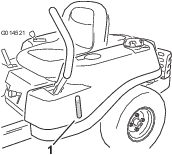
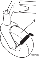
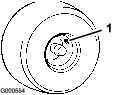
Maintain the air pressure in the front and rear tires as specified. Uneven tire pressure can cause uneven cut. Check the pressure at the valve stem (Figure 42). Check the tires when they are cold to get the most accurate pressure reading.
Refer to the maximum pressure suggested by the tire manufacturer on the sidewall of the caster wheel tires.
Inflate the rear drive wheel tires to 13 psi.
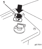
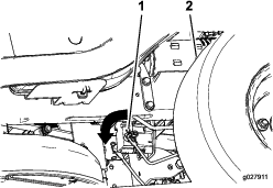
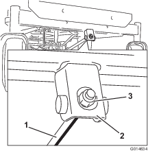
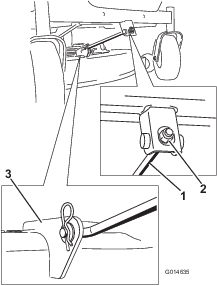
Releasing the Electric Brake
The electric brake releases by manually rotating the link arms forward. Once the electric brake is energized the brake will reset.
To release the brake:
-
Turn the ignition key to the Off position or disconnect the battery.
-
Locate the shaft on the electric brake where the brake-link arms are connected.
-
Rotate the shaft forward to release the brake.
Hydraulic System Maintenance
Hydraulic System Oil Specification
Oil Type: Toro HYPR-OIL® 500 or 20w-50 motor oil.
System Capacity:approximately 4.495 liter (152 oz) with a filter change.
Checking the Hydraulic-Oil Level
| Maintenance Service Interval | Maintenance Procedure |
|---|---|
| Every 25 hours |
|
Check expansion reservoir and if necessary add the specified oil to the Full Cold line.
Changing the Hydraulic System Oil and Filters
| Maintenance Service Interval | Maintenance Procedure |
|---|---|
| After the first 50 hours |
|
| Every 400 hours |
|
Important: The bleeding process is repeated until the oil remains at the Full Cold line in the reservoir after purging. Failure to properly perform this procedure can result in irreparable damage to the transaxle drive system.
Note: The filter and oil are changed at the same time. Do not reuse oil. Once the new filter is installed and oil is added any air in the system must be purged.
Removing Hydraulic System Filters
-
Stop engine, wait for all moving parts to stop, and allow engine to cool. Remove the key and engage the parking brake.
-
Raise the rear of machine up and support with jack stands (or equivalent support) just high enough to allow drive wheels to turn freely.
-
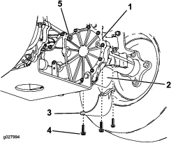
Locate the filter and filter guards on each transaxle drive system (Figure 46). Remove three screws securing the filter guard and guard.
-
Carefully clean area around filters. It is important that no dirt or contamination enter hydraulic system.
-
Place a container below the filter to catch the oil that drains when the filter and vent plugs are removed.
-
Locate and remove the vent plug on each transmission
-
Unscrew the filter to remove and allow oil to drain from drive system.
Repeat this procedure for both filters.
Installing the Hydraulic System Filters
-
Apply a thin coat of the specified oil on the surface of the rubber seal of each filter.
-
Turn the filter clockwise until rubber seal contacts the filter adapter then tighten the filter an additional 3/4 to 1 full turn. Repeat for the other filter
-
Install the filter guards over each filter as previously removed. Use the three screws to secure the filter guards.
-
Verify the vent plugs are removed before adding the oil.
-
Slowly pour the specified oil through expansion reservoir until oil comes out of one of the vent plug holes. Stop and install that vent plug. Torque the plug to 180 in-lb (20.3 N-m).
-
Continue to add oil through the expansion reservoir until oil comes out of the remaining vent plug hole on the second transmission. Stop and install that vent plug. Torque the plug to 180 in-lb (20.3 N-m).
-
Continue to add oil through the expansion reservoir until it reaches the Full Cold line on the expansion reservoir.
-
Proceed to the Bleeding the Hydraulic System section.
Important: Failure to perform the Bleeding the Hydraulic System procedure after changing hydraulic filters and oil can result in irreparable damage to the transaxle drive system.
Bleeding the Hydraulic System
-
Enter the operator's position. Start engine and move throttle control ahead to 1/2 throttle position. Disengage parking brake.
-
Move the bypass levers into the pushing the machine position; refer to the Pushing the Machine by Hand section in Operation. With the bypass valves open and the engine running, slowly move the motion control levers in both forward and reverse (5 or 6 times).
-
Move the bypass levers into the operating the machine position. With the bypass valve closed and the engine running, slowly move the directional control in both forward and reverse directions (5 to 6 times).
-
Stop the engine and check the oil level in the expansion reservoir. Add the specified oil as until it reaches the Full Cold line on the expansion reservoir.
-
-
Repeat step 1 until all the air is completely purged from the system.
When the transaxle operates at normal noise levels and moves smoothly forward and reverse at normal speeds, then the transaxle is considered purged.
-
Check the oil level in the expansion reservoir one last time. Add the specified oil as until it reaches the Full Cold line on the expansion reservoir if necessary.
Mower Maintenance
Servicing the Cutting Blades
Maintain sharp blades throughout the cutting season because sharp blades cut cleanly without tearing or shredding the grass blades. Tearing and shredding turns grass brown at the edges, which slows growth and increases the chance of disease.
Check the cutter blades daily for sharpness, and for any wear or damage. File down any nicks and sharpen the blades as necessary. If a blade is damaged or worn, replace it immediately with a genuine Toro replacement blade. For convenient sharpening and replacement, you may want to keep extra blades on hand.
Warning
A worn or damaged blade can break, and a piece of the blade could be thrown into the operator's or bystander's area, resulting in serious personal injury or death.
-
Inspect the blade periodically for wear or damage.
-
Replace a worn or damaged blade.
Before Inspecting or Servicing the Blades
Park the machine on a level surface, disengage the blade control switch, and move the motion control levers outward to the park position. Stop the engine and remove the key.
Inspecting the Blades
| Maintenance Service Interval | Maintenance Procedure |
|---|---|
| Before each use or daily |
|
-
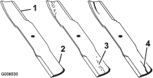
Inspect the cutting edges (Figure 48). If the edges are not sharp or have nicks, remove and sharpen the blades; refer to Sharpening the Blades.
-
Inspect the blades, especially the curved area (Figure 48). If you notice any damage, wear, or a slot forming in this area (items 3 and 4 in Figure 48), immediately install a new blade.
Checking for Bent Blades
Note: The machine must be on a level surface for the following procedure.
-
Raise the mower deck to the highest height-of-cut position; also considered the 'transport' position.
-
While wearing thickly padded gloves or other adequate hand protection slowly rotate blade to be measured into a position that allows effective measurement of the distance between the cutting edge and the level surface the machine is on.
-
Measure from the tip of the blade to the flat surface here.
-
Rotate the same blade 180 degrees so that the opposing cutting edge is now in the same position.
-
Measure from the tip of the blade to the flat surface here. The variance should be no more than 3 mm (1/8 inch).
Warning
A blade that is bent or damaged could break apart and could seriously injure or kill you or bystanders.
-
Always replace bent or damaged blade with a new blade.
-
Never file or create sharp notches in the edges or surfaces of blade.
-
If the difference between A and B is greater than 1/8 inch (3mm) replace the blade with a new blade. Refer to Removing the Blades and Installing the Blades.
Note: If a bent blade is replaced with a new one and the dimension obtained continues to exceed 1/8 inch (3mm), the blade spindle could be bent. Contact an Authorized Toro Dealer for service.
-
If the variance is within constraints, move to the next blade..
-
Repeat this procedure on each blade.
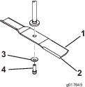
Removing the Blades
The blades must be replaced if a solid object is hit, if the blade is out of balance, or the blade is bent. To ensure optimum performance and continued safety conformance of the machine, use genuine Toro replacement blades. Replacement blades made by other manufacturers may result in non-conformance with safety standards.
Hold the blade end using a rag or thickly-padded glove. Remove the blade bolt, curved washer, and blade from the spindle shaft (Figure 53).
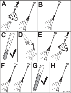
Sharpening the Blades
-
Use a file to sharpen the cutting edge at both ends of the blade (Figure 54). Maintain the original angle. The blade retains its balance if the same amount of material is removed from both cutting edges.

-
Check the balance of the blade by putting it on a blade balancer (Figure 55). If the blade stays in a horizontal position, the blade is balanced and can be used. If the blade is not balanced, file some metal off the end of the sail area only (Figure 54). Repeat this procedure until the blade is balanced.

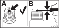
Installing the Blades
-
Install the blade onto the spindle shaft (Figure 53).
Important: The curved part of the blade must be pointing upward toward the inside of the mower to ensure proper cutting.
-
Install the curved washer (cupped side toward the blade) and the blade bolt (Figure 53).
-
Torque the blade bolt to 47-48 N-m (35-65 ft-lb).
Leveling the Mower Deck
Check to ensure the mower deck is level any time you install the mower or when you see an uneven cut on your lawn.
The mower deck must be checked for bent blades prior to leveling; any bent blades must be removed and replaced. Refer to the Checking for Bent Blades procedure before continuing.
The mower deck must be leveled side-to-side first then the front to rear slope can be adjusted.
Requirements:
-
The machine must be on a level surface.
-
All 4 tire must be properly inflated. Refer to Checking the Tire Pressure.
Leveling from Side to Side
-
Park the machine on a level surface and disengage the blade-control switch.
-
Move the motion-control levers outward to the park position, stop the engine, remove the key, and wait for all moving parts to stop before leaving the operating position.
-
Set the height-of-cut lever to middle position.
-
Carefully rotate the blade(s) so that they are all side to side (Figure 56).
-
Measure between the outside cutting edges and the flat surface (Figure 56). If both measurements are not within 5 mm (3/16 inch), an adjustment is required; continue with this procedure.
-
Move to the left side of the machine.
-
Loosen the side locking nut.
-
Raise or lower the left side of the mower deck by rotating the rear nut. (Figure 57).
Note: Rotate the rear nut clockwise to raise the mower deck; rotate the rear nut counter-clockwise to lower the mower deck.

-
Check the side-to-side adjustments again. Repeat this procedure until the measurements are correct.
-
Continue leveling the deck by checking the front-to-rear blade slope; refer to Adjusting the Front-to-Rear Blade Slope.
Adjusting the Front-to-Rear Blade Slope
Check the front-to-rear blade level any time you install the mower. If the front of the mower is more than 5/16 inch (7.9 mm) lower than the rear of the mower, adjust the blade level using the following instructions:
-
Park the machine on a level surface and disengage the blade control switch.
-
Move the motion control levers outward to the park position, stop the engine, remove the key, and wait for all moving parts to stop before leaving the operating position.
-
Set the height-of-cut lever to middle position.
Note: Check and adjust the side-to-side blade level. If you have not checked the setting; refer to Leveling from Side to Side.
-
Carefully rotate the blades so they are facing front to rear (Figure 58).
-
Measure from the tip of the front blade to the flat surface and the tip of the rear blade to the flat surface (Figure 58). If the front blade tip is not 1/16 to 5/16 inch (1.6 to 7.9 mm) lower than the rear blade tip, adjust the front locknut.
-
To adjust the front-to-rear blade slope, rotate the adjustment nut in the front of the mower (Figure 59).
-
To raise the front of the mower, tighten the adjustment nut. To lower the front of the mower, loosen the adjustment nut.
-
After adjustment, check the front-to-rear slope again. Continue adjusting the nut until the front blade tip is 1/16 to 5/16 inch (1.6 to 7.9 mm) lower than the rear blade tip (Figure 58).
-
When the front-to-rear blade slope is correct check the side-to-side level of the mower again; refer to Leveling from Side to Side.
Removing the Mower
-
Park the machine on a level surface and disengage the blade control switch.
-
Move the motion control levers outward to the park position, stop the engine, remove the key, and wait for all moving parts to stop before leaving the operating position.
-
Lower the height-of-cut lever to the lowest position.
-
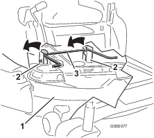
Remove the hairpin cotter from the front support rod and remove the rod from the deck bracket (Figure 60). Carefully lower the front of the mower deck to the ground.
-
Using the mower deck handles, lift the mower deck and hanger brackets clear of the rear lift rod and lower the mower carefully to the ground (Figure 61 and Figure 64).
-
Slide the mower deck rearward to remove the mower belt from the engine pulley.
-
Slide the mower deck out from underneath the machine.
Note: Retain all parts for future installation.
Replacing the Grass Deflector
| Maintenance Service Interval | Maintenance Procedure |
|---|---|
| Before each use or daily |
|
Warning
An uncovered discharge opening could allow the lawn mower to throw objects in the operator’s or bystander’s direction and result in serious injury. Also, contact with the blade could occur.
Never operate the lawn mower unless you install a mulch plate, discharge deflector, or grass collection system.
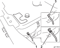
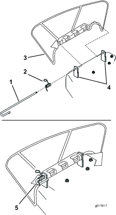
Inspect the grass deflector for damage before each use. Replace any damaged parts before use.
-
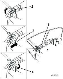
Disengage the spring from the notch in the deflector bracket and slide the rod out of the welded deck brackets, spring, and discharge deflector (Figure 62). Remove the damaged or worn discharge deflector.
-
Position the new discharge deflector with the bracket ends between the welded brackets on the deck as shown in Figure 62.
-
Install the spring onto the straight end of the rod. Position the spring on the rod as shown in so the shorter spring end is coming from under the rod before the bend and going over the rod as it returns from the bend.
-
Lift the loop end of the spring and place it into the notch on the deflector bracket (Figure 63).
-
Secure the rod and spring assembly by twisting it so the short end of the rod can be placed behind the front bracket welded to the deck (Figure 63).
Important: The grass deflector must be spring loaded in the down position. Lift the deflector up to test that it snaps to the full down position.
Mower Belt Maintenance
Inspecting the Belts
| Maintenance Service Interval | Maintenance Procedure |
|---|---|
| Every 25 hours |
|
Check the belts for cracks, frayed edges, burn marks, or any other damage. Replace damaged belts.
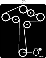
Replacing the Mower Belt
Squealing when the belt is rotating, blades slipping when cutting grass, frayed belt edges, burn marks, and cracks are signs of a worn mower belt. Replace the mower belt if any of these conditions are evident.
-
Park the machine on a level surface and disengage the blade control switch.
-
Move the motion control levers outward to the park position, stop the engine, remove the key, and wait for all moving parts to stop before leaving the operating position.
-
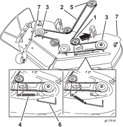
Set the height-of-cut at the lowest cutting position [1-1/2 inch (38 mm)].
-
Using a spring removal tool, (Toro part no. 92-5771), remove the idler spring from the deck hook to remove tension on the idler pulley and roll the belt off of the pulleys (Figure 64).
Warning
The spring is under tension when installed and can cause personal injury.
Be careful when removing the belt.
-
Route the new belt around the engine pulley and mower pulleys (Figure 64).
-
Using a spring removal tool, (Toro part no. 92-5771), install the idler spring over the deck hook and placing tension on the idler pulley and mower belt (Figure 64).
Installing the Mower
-
Park the machine on a level surface and disengage the blade control switch.
-
Move the motion control levers outward to the park position, stop the engine, remove the key, and wait for all moving parts to stop before leaving the operating position.
-
Slide the mower under the machine.
-
Lower the height-of-cut lever to the lowest position.
-
Lift the rear of the mower deck and guide the hanger brackets over the rear lift rod (Figure 61).
-
Attach the front support rod to the mower deck with the clevis pin and hairpin cotter (Figure 60).
-
Install the mower belt onto the engine pulley; refer to Replacing the Mower Belt.
Cleaning
Washing the Underside of the Mower
| Maintenance Service Interval | Maintenance Procedure |
|---|---|
| After each use |
|
Wash the underside of the mower after each use to prevent grass buildup for improved mulch action and clipping dispersal.
Important: You can wash the machine with mild detergent and water. Do not pressure wash the machine. Avoid excessive use of water, especially near the control panel, under the seat, around the engine, hydraulic pumps, and motors.
-
Park the machine on a level surface and disengage the blade control switch.
-
Move the motion control levers outward to the park position, stop the engine, remove the key, and wait for all moving parts to stop before leaving the operating position.
-
Attach the hose coupling to the end of the mower washout fitting, and turn the water on high (Figure 65).
Note: Spread petroleum jelly on the washout fitting O-ring to make the coupling slide on easier and protect the O-ring.
-
Lower the mower to the lowest height-of-cut.
-
Sit on the seat and start the engine. Engage the blade control switch and let the mower run for one to three minutes.
-
Disengage the blade control switch, stop the engine, and remove the ignition key. Wait for all moving parts to stop.
-
Turn the water off and remove the coupling from the washout fitting.
Note: If the mower is not clean after one washing, soak it and let it stand for 30 minutes. Then repeat the process.
-
Run the machine and mower blades again for one to three minutes to remove excess water.
-
Turn off the mower blades.
Warning
A broken or missing washout fitting could expose you and others to thrown objects or blade contact. Contact with blade or thrown debris can cause injury or death.
-
Replace broken or missing washout fitting immediately, before using mower again.
-
Never put your hands or feet under the mower or through openings in the mower.
-
Storage
Cleaning and Storage
-
Disengage the blade control switch, move the motion controls outward to the park position, stop the engine, and remove the key.
-
Remove grass clippings, dirt, and grime from the external parts of the entire machine, especially the engine. Clean dirt and chaff from the outside of the engine cylinder head fins and blower housing.
Important: You can wash the machine with mild detergent and water. Do not pressure wash the machine. Avoid excessive use of water, especially near the control panel, under the seat, around the engine, hydraulic pumps, and motors.
-
Service the air cleaner; refer to Servicing the Air Cleaner.
-
Grease and oil the machine; refer to Lubrication.
-
Change the crankcase oil and filter; refer to Servicing the Engine Oil.
-
Check the tire pressure; refer to Checking the Tire Pressure.
-
Charge the battery; refer to Charging the Battery.
-
Check the condition of the blades; refer to Servicing the Cutting Blades.
-
Prepare the machine for storage when non-use occurs over 30 days. Prepare the machine for storage as follows.
-
Add a petroleum based stabilizer/conditioner to the fuel in the tank. Follow the mixing instructions from the stabilizer manufacturer. Do not use an alcohol based stabilizer (ethanol or methanol).
Note: A fuel stabilizer/conditioner is most effective when mixed with fresh gasoline and used at all times.
Run the engine to distribute the conditioned fuel through the fuel system (5 minutes).
Important: Do not store stabilizer/conditioned gasoline over 90 days.
-
Remove the spark plug(s) and check its condition; refer to Servicing the Spark Plug. With the spark plug(s) removed from the engine, pour two tablespoons of engine oil into the spark plug hole. Use the starter to crank the engine and distribute the oil inside the cylinder. Install the spark plug(s). Do not install the wire on the spark plug(s).
-
Clean any dirt and chaff from the top of the mower.
-
Scrape any heavy buildup of grass and dirt from the underside of the mower, then wash the mower with a garden hose.
-
Check the condition of the drive and mower belts.
-
Check and tighten all bolts, nuts, and screws. Repair or replace any part that is worn or damaged.
-
Paint all scratched or bare metal surfaces. Paint is available from your Authorized Service Dealer.
-
Store the machine in a clean, dry garage or storage area. Remove the key from the ignition switch and keep it in a memorable place. Cover the machine to protect it and keep it clean.
Troubleshooting
| Problem | Possible Cause | Corrective Action |
|---|---|---|
| The fuel tank is showing signs of collapsing or the machine is showing signs of frequently running out of fuel. |
|
|
| The engine overheats. |
|
|
| The starter does not crank. |
|
|
| The engine does not start, starts hard, or fails to keep running. |
|
|
| The engine loses power. |
|
|
| The machine does not drive. |
|
|
| There is abnormal vibration. |
|
|
| The cutting height is uneven. |
|
|
| The blades do not rotate. |
|
|
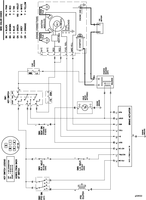
Schematics
Electrical Diagram