CALIFORNIA
Proposition 65 Warning
Note: Determine the left and right sides of the machine from the normal operating position.
Note: You can use a hoist for better access under the machine.
Park the machine on a level surface.
Engage the parking brake.
Shut off the engine and remove the key.
Allow the machine to cool.

Incorrect battery cable routing could damage the machine and cables, causing sparks. Sparks can cause the battery gasses to explode, resulting in personal injury.
Always disconnect the negative (black) battery cable before disconnecting the positive (red) cable.
Always connect the positive (red) battery cable before connecting the negative (black) cable.
Always keep the battery strap in place to protect and secure the battery.
Battery terminals or metal tools could short against metal machine components, causing sparks. Sparks can cause the battery gasses to explode, resulting in personal injury.
When removing or installing the battery, do not allow the battery terminals to touch any metal parts of the machine.
Do not allow metal tools to short between the battery terminals and metal parts of the machine.
Squeeze the sides of the battery cover and remove the cover from the top of the battery (Figure 2).
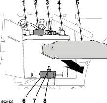
Disconnect the negative-battery cable from the terminal of the battery (Figure 2).
Disconnect the positive battery cable from the terminal of the battery (Figure 2).
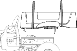
Cargo box weight: approximately 57 kg (126 lb)
Lift the latch lever on either side of the machine, near the forward corner of the cargo bed, and fully raise the bed (Figure 3).
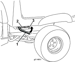
Secure the cargo bed by pulling the prop rod into the rear detent at the end of the slot located in the left side of the machine (Figure 3).
Note: For machines with a bolt-on rod-support bracket, pull the prop rod into the rear detent at the end of the slot in the bracket.
Attach the lifting equipment to the front and rear of the cargo bed.
Note: Raise the lifting equipment at the front of the bed until the front of the bed is supported.
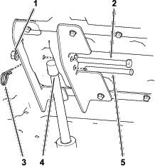
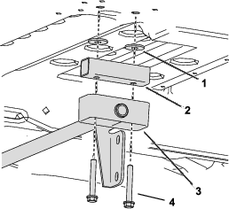
Remove the hairpin cotter and washer that secure the prop rod to the bottom of the bed (Figure 4).
Slide the prop rod forward to remove it from the bracket on the frame (Figure 4).
Note: Retain the hardware for cargo bed installation.
Lower the front of the bed.
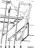
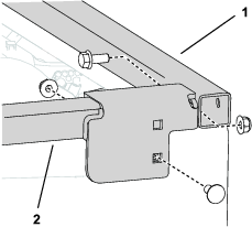
Remove the 4 flanged-head bolts (3/8 x 1 inch) that secure the hinge brackets of the cargo bed to the rear frame channel of the machine (Figure 5).
Note: Retain the hardware for cargo bed installation.
Lift the latch lever on either side of the machine, near the forward corner of the cargo bed (Figure 3).
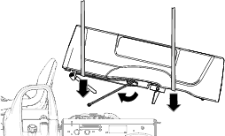
Lift the cargo bed up and off the machine (Figure 6).
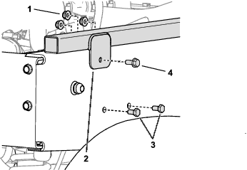
Remove the hex-head bolt (1/2 x 5-1/2 inches) and locknut (1/2 inch) from the inboard and outboard lift brackets (Figure 7).
Note: Retain the hardware for cargo bed installation.
Remove the hairpin cotter from the clevis pin (3-1/2 inches), and remove the clevis pin (3-1/2 inches) from the lift actuator rod (Figure 7).
Note: Retain the hardware for cargo bed installation.
Remove the 4 flanged-head bolts (3/8 x 1 inch) that secure the hinge brackets of the cargo bed to the rear frame channel of the machine (Figure 5).
Note: Retain the hardware for cargo bed installation.
Lift the cargo bed up and off the machine (Figure 6).
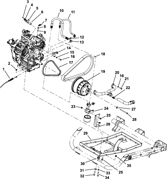
Refer to Figure 8 and Figure 9 for this procedure.
Important: To prevent contaminants from entering the fuel system and engine, ensure that all hoses and engine openings are covered or plugged after disconnecting.
Note: Keep any parts removed in this procedure for later installation unless otherwise stated.
Drain the oil from the engine before removing the engine; refer to your Operator’s Manual.
Disconnect the choke and throttle cables from the engine, but do not remove them from the cable brackets.
Disconnect the air intake hose from the air cleaner.
In certain conditions, fuel is extremely flammable and highly explosive. A fire or explosion from fuel can burn you and others and can damage property.
Never fill the fuel tank inside an enclosed trailer.
Never smoke when handling fuel, and stay away from an open flame or where fuel fumes may be ignited by a spark.
Store fuel in an approved container and keep it out of the reach of children. Never buy more than a 30-day supply of fuel.
In certain conditions during fueling, static electricity can be released and cause a spark, which can ignite the fuel vapors. A fire or explosion from fuel can burn you and others and can damage property.
Always place fuel containers on the ground away from your machine before filling.
Do not fill fuel containers inside a machine or on a truck or trailer bed because interior carpets or plastic truck bed liners may insulate the container and slow the loss of any static charge.
Fuel is harmful or fatal if swallowed. Long-term exposure to vapors can cause serious injury and illness.
Avoid prolonged breathing of vapors.
Keep your face away from the nozzle and fuel tank opening.
Keep fuel away from your eyes and skin.
Disconnect the fuel inlet hose from the fuel pump; clamp the hose so that fuel does not leak.
Remove the exhaust manifold from the engine.
Unthread the 2 oil hoses from their fittings in the engine.
Disconnect the wire harness terminal from the front side of the engine.
Parts needed for this procedure:
| Engine | 1 |
| Air intake hose | 1 |
| Hose clamp—air cleaner side | 1 |
| Hose clamp—engine side | 1 |
| Air cleaner bracket | 1 |
| Bolt | 2 |
| Locknut | 2 |
| Nut | 2 |
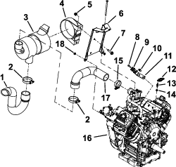
Refer to Figure 8 and Figure 9 for this procedure.
Install the oil hose fittings into the side of the engine.
Note: Install the elbowed fitting into the lower orifice and install the straight fitting to the upper orifice.
Install the air cleaner to the air cleaner bracket.
Install the air cleaner bracket to the engine, and install the air intake hose with the provided hose clamps.
Attach a short section of chain between 2 lift points on the engine and connect the hoist to the center of the chain.
Slowly lower the engine into the machine with one person operating the hoist and another guiding the engine into the frame.
Note: The crankshaft should be facing the right side of the machine when installed.
Thread the ball stud and spring keeper into the engine and attach the spring.
Install the choke and throttle cables and cable brackets to the engine.
Align the starter belt with the engine pulleys.
Apply medium-strength thread-locking compound (such as Blue Loctite® 242) to the clutch screw and install the clutch assembly to the engine crankshaft.
Align the drive belt with the clutch assembly.
Install the exhaust manifold to the engine and connect it to the exhaust pipe with the coupler springs.
Install the 4 flange nuts and 4 cap screws securing the engine to the engine tray.
Thread the 2 oil hoses into their fittings in the engine.
Note: Thread the straight hose end to the elbowed fitting on the engine and thread the elbowed hose end onto the straight hose fitting.
Connect the ground wire to the front side of the engine.
Connect the fuel inlet hose to the fuel pump.
Connect the air intake hose to the air cleaner and the engine using hose clamps.
Fill the engine with oil; refer to your Operator’s Manual.
Parts needed for this procedure:
| Front tube frame | 1 |
| Right bed spacer assembly | 1 |
| Left bed spacer assembly | 1 |
| Pivot bed spacer | 2 |
| Screw | 4 |
| Carriage bolt | 2 |
| Bolt | 4 |
| Nut | 6 |
Remove the hinge bracket assembly from the bottom of the detached cargo bed.
Align the pivot bed spacers directly above the pivot bushings, and install the hinge bracket assembly to the cargo bed using the long screws (Figure 10).
Place the front tube frame flush with the forward edge of the bed frame assembly.
Connect the right bed spacer assembly to the front tube frame with a bolt and to the bed frame assembly with a carriage bolt as shown in Figure 11.
Important: Move any components that are behind the frame in the path of the drill before drilling.
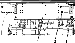
On the right side of the machine, detach the solenoid bracket and move it out of the path of the drill (Figure 12).
Drill a hole in the bed frame assembly using the mounting tab of the side bed spacer assemblies as a template and secure the frame assembly with a short bolt and a nut (Figure 12).
Repeat these steps on the other side of the machine.
Rotate the cargo bed so that the hinge-bracket assembly and prop rod are facing downward (Figure 13).
Using lifting equipment at the front and rear of the cargo bed, raise the cargo bed, and align it over the frame of the machine with the hinge-bracket assembly facing rearward (Figure 13).
Adjust the height and position of the lifting equipment so that the short leg of the prop rod is aligned with the detent slot at the end of the prop rod slot in the left frame channel or prop rod bracket (Figure 13).
Note: You will have to angle the cargo bed with the lifting equipment in order to align the prop rod to the detent slot.
Rotate the prop rod forward and insert the short leg of the rod through the detent slot (Figure 13 and Figure 14).
Move the cargo bed and prop rod rearward until the hinge-bracket assembly aligns over the rear frame channel (Figure 14).
Carefully lower the cargo bed until the holes in the hinge brackets align with the mounting holes for the cargo bed in the rear frame channel (Figure 15).
Secure the hinge brackets to the rear frame channel using the previously removed 4 flanged-head bolts (3/8 x 1 inch) as shown in Figure 15.
Torque the 4 flanged-head bolts to 37 to 45 N∙m (27 to 33 ft-lb).
Rotate the cargo bed so that the hinge-bracket assembly and prop rod are facing downward (Figure 13).
Using lifting equipment at the front and rear of the cargo bed, raise the cargo bed, and align it over the frame of the machine with the hinge-bracket assembly facing rearward (Figure 13).
Secure the lift actuator rod to the inboard and outboard lift brackets using the previously removed hex-head bolt (1/2 x 5-1/2 inches), locknut (1/2 inch), clevis pin (3-1/2 inches), and hairpin cotter (Figure 16).
Secure the hinge brackets to the rear frame channel using the previously removed 4 flanged-head bolts (3/8 x 1 inch) as shown in Figure 15.
Torque the 4 flanged-head bolts to 37 to 45 N∙m (27 to 33 ft-lb).
Connect the positive battery cable to the terminal of the battery (Figure 2).
Connect the negative battery cable to the terminal of the battery (Figure 2).
Install the battery cover onto the top of the battery (Figure 2).