


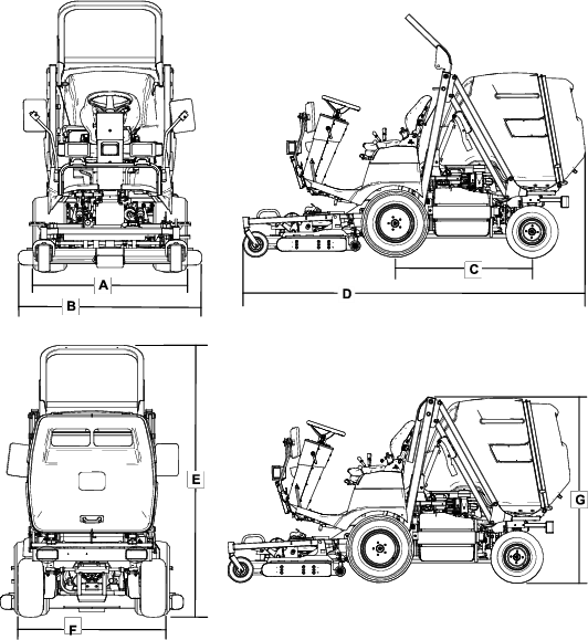
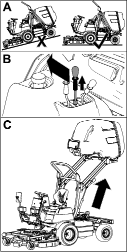
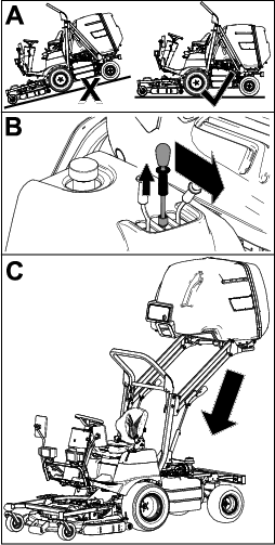
Maintenance
Note: Download a free copy of the electrical or hydraulic schematic by visiting www.Toro.com and searching for your machine from the MANUALS link on the home page.
Recommended Maintenance Schedule(s)
| Maintenance Service Interval | Maintenance Procedure |
|---|---|
| After the first operating hour |
|
| After the first 10 operating hours |
|
| After the first 50 operating hours |
|
| Before each use or daily |
|
| Every 50 hours |
|
| Every 100 hours |
|
| Every 200 hours |
|
| Every 250 hours |
|
| Every 400 hours |
|
| Every 500 hours |
|
| Every 1,500 hours |
|
| Monthly |
|
Pre-Maintenance Procedures
Pre-Maintenance Safety
-
Before adjusting, cleaning, repairing, or leaving the machine, do the following:
-
Park the machine on a level surface.
-
Move the throttle switch to the low-idle position.
-
Disengage the mower deck.
-
Lower the mower deck.
-
Ensure that the traction is in neutral.
-
Engage the parking brake.
-
Shut off the engine and remove the key.
-
Wait for all moving parts to stop.
-
Allow machine components to cool before performing maintenance.
-
-
If possible, do not perform maintenance while the engine is running. Keep away from moving parts.
-
Use jack stands to support the machine or components when required.
-
Carefully release pressure from components with stored energy.
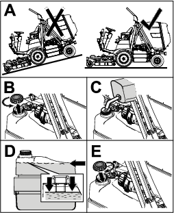
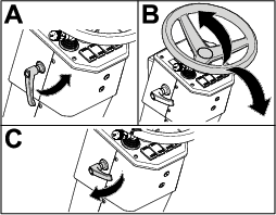
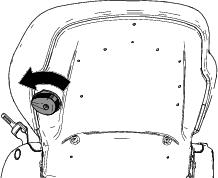
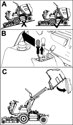
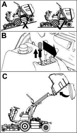
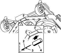
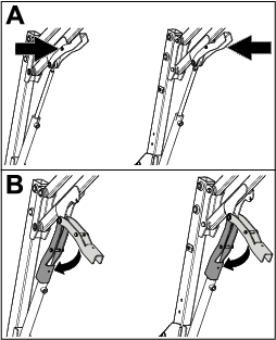
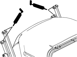
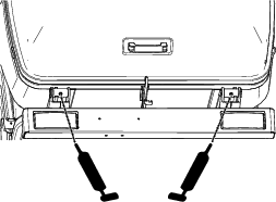
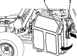
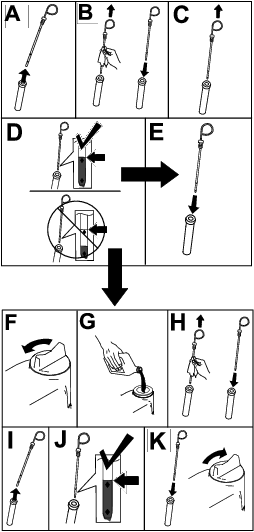
Securing the Hopper in the Raised Position
-
Park the machine on a level surface.
-
Raise the hopper to the fully raised position; refer to Raising the Hopper.
-
Secure the hopper by performing the following:
-
Push the pin on magnetic safety lock inward (Figure 39).
-
While still holding the pin in, lower magnetic safety lock onto the hydraulic cylinder (Figure 39).
-
Repeat steps 1 and 2 on the other side.
-
Lubrication
Greasing the Mower Deck
Grease specification: No. 2 lithium grease
Important: Dusty and dirty operating conditions could cause dirt to get into the bearings and bushings, resulting in accelerated wear.
Note: Lubricate the grease fittings immediately after every washing, regardless of interval specified.
-
Wipe grease fitting clean so foreign matter cannot be forced into the bearing or bushing.
-
Pump grease into the bearing or bushing.
-
Wipe off excess grease.
Greasing the Bearings and Bushings
Grease specification: No. 2 lithium grease
Important: Dusty and dirty operating conditions could cause dirt to get into the bearings and bushings, resulting in accelerated wear.
Note: Lubricate the grease fittings immediately after every washing, regardless of interval specified.
Note: Bearing life can be negatively affected by improper wash-down procedures. Do not wash down the machine when it is still hot and avoid directing high-pressure or high-volume spray at the bearings.
-
Wipe grease fitting clean so foreign matter cannot be forced into the bearing or bushing.
-
Pump grease into the bearing or bushing.
-
Wipe off excess grease.
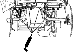
The bearing and bushing lubrication points are as follows:
-
Hopper arms—upper (Figure 41)
-
Hopper arms—lower, front (Figure 42)
-
Hopper arms—lower, rear(Figure 43)
-
Hopper pivots (Figure 44)
-
Tie-rod ends and rear pivot (Figure 45)
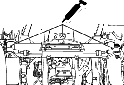
-
Brake pivot bushings and drive shaft (Figure 46)
Engine Maintenance
Engine Safety
-
Shut off the engine before checking the oil or adding oil to the crankcase.
-
Do not change the governor speed or overspeed the engine.
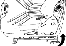
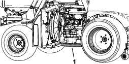
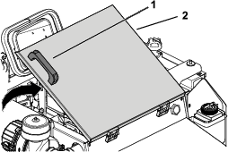
Accessing the Engine
Accessing the Engine from the Engine-Access Cover
-
Raise the hopper to the fully raised position and secure it with the magnetic safety locks; refer to Raising the Hopper and Securing the Hopper in the Raised Position.
-
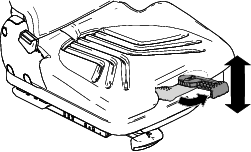
Using the handle on the engine-access cover, raise the cover to access the engine (Figure 47).
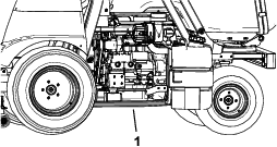
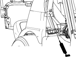
Accessing the Engine from the Right side
-
Push the latch on the radiator inward toward the radiator (Figure 48).
-
Using the handle on the side of the radiator, rotate the radiator to access the engine (Figure 48).
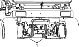
Accessing the Engine from the Left Side
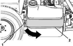
Remove bolt from the left side of the fuel-tank bracket and rotate the fuel tank to the right to access the engine (Figure 49).
Note: You must have the steering wheel rotated to the fully locked position to rotate the fuel tank out fully.
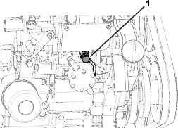
Servicing the Air Cleaner
Note: Replace the air cleaner more frequently (every few hours) if operating conditions are extremely dusty or sandy.
Cleaning the Air-Cleaner Cover
Check the air-cleaner body for damage which could cause an air leak. Replace a damaged air-cleaner body.
Clean the air-cleaner cover as shown in Figure 50.
Servicing the Air-Cleaner Filters
-
Gently slide the primary filter out of the air-cleaner body (Figure 51).
Note: Avoid knocking the filter into the side of the body.
Important: Do not attempt to clean the primary filter.
-
Remove the safety filter (if equipped).
Note: Remove the safety filter only if you intend to replace it.
Important: Never attempt to clean the safety filter. If the safety filter is dirty, then the primary filter is damaged, and you should replace both filters.
-
Inspect the new filter(s) for damage by looking into the filter while shining a bright light on the outside of the filter.
Note: Holes in the filter appear as bright spots. Inspect the element for tears, an oily film, or damage to the rubber seal. If the filter is damaged, do not use it.
-
If you are replacing the safety filter, carefully slide the new filter into the filter body (Figure 51).
Important: To prevent engine damage, always operate the engine with both air filters and cover installed.
-
Carefully slide the new primary filter over the safety filter and ensure that it is fully seated by pushing on the outer rim of the filter while installing it.
Important: Do not press on the soft inside area of the filter.
-
Install the air-cleaner cover with the side indicated as “UP facing upward and secure the latches (Figure 51).
Servicing the Engine Oil
The engine ships with oil in the crankcase.
Crankcase capacity: approximately 3.4L (3.6US qt) with the filter.
Engine oil specification:
-
Engine oil-type—API Classification Level Required: CH-4, CI-4 or higher.
-
Engine oil visacosity
-
Preferred oil: SAE 15W-40 (above 0°F)
-
Alternate oil: SAE 10W-30 or 5W-30 (all temperatures)
-
Note: Toro Premium Engine Oil is available from your distributor in either 15W-40 or 10W-30 viscosity. See the parts catalog for part numbers.
Checking the Engine-Oil Level
Note: The best time to check the engine oil is when the engine is cool before it has been started for the day. If you have already run the engine, allow the oil to drain back down to the sump for at least 10 minutes before checking. If the oil level is at or below the low mark on the dipstick, add oil to bring the oil level to the high mark. Do not overfill. If the oil level is between the high and low marks, you do not need to add oil.
Check the engine-oil level as shown in Figure 52.
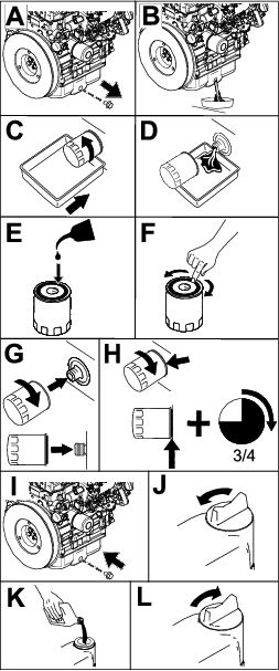
Changing the Engine Oil And Filter
Note: Change the engine oil and filter more frequently when the operating conditions are extremely dusty or sandy.
-
Start the engine and let it run 5 minutes to allow the oil to warm up.
-
Park the machine on a level surface.
-
Disengage the PTO, lower the mower deck, and engage the parking brake.
-
Raise and secure the hopper, and open the engine-access cover; refer to Accessing the Engine from the Engine-Access Cover.
-
Shut off the engine and remove the key.
-
Change the engine oil and engine-oil filter as shown in Figure 53.
Note: Tighten the filter until the oil-filter gasket touches the engine, and then turn it an extra 3/4 turn.
Fuel System Maintenance
Note: Refer to Adding Fuel for proper the fuel recommendations.
Danger
Under certain conditions, diesel fuel and fuel vapors are highly flammable and explosive. A fire or explosion from fuel can burn you and others and can cause property damage.
Never smoke when handling fuel, and stay away from an open flame or where fuel fumes may be ignited by a spark.
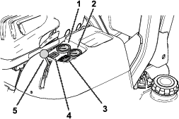
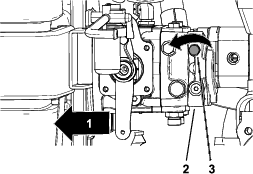
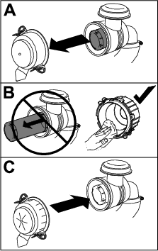
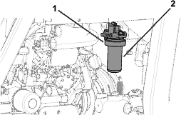
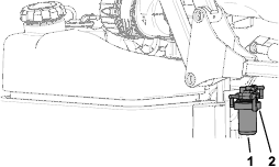
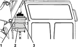
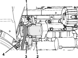
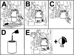
Replacing the Fuel-Filter Element
-
Clean the area around the fuel-filter head (Figure 54).
-
Remove the filter and clean the filter-head-mounting surface (Figure 54).
-
Lubricate the filter gasket with clean, lubricating engine oil; refer to the engine owner's manual (included with the machine) for additional information.
-
Tighten the dry filter canister, by hand, until the gasket contacts the filter head, then rotate it an additional 1/2 turn.
-
Pump the lever on the left side of the fuel pump until you fill the fuel-filter bowl (Figure 55).
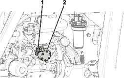
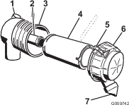
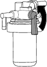
Replacing the Fuel-Filter Element
-
Clean the area around the fuel-filter head (Figure 56).
-
Turn the lever on the fuel-filter head counterclockwise to the OFF position (Figure 57).
-
Remove the filter and clean the filter-head-mounting surface (Figure 56).
-
Lubricate the filter gasket with clean, lubricating engine oil; refer to the engine owner's manual (included with the machine) for additional information.
-
Install the dry filter canister, by hand, until the gasket contacts the filter head, then rotate it an additional 1/2 turn.
-
Turn the lever on the fuel-filter head clockwise to the ON position (Figure 57).
-
Start the engine and check for fuel leaks around the filter head.
Cleaning the Fuel Tank
Empty and clean tank if fuel system becomes contaminated or if you store the machine for an extended period of time. Use clean diesel fuel to flush out the tank.
Close sectionInspecting the Fuel Lines and Connections
Inspect the fuel lines for deterioration, damage, or loose connections.
Close sectionElectrical System Maintenance
Electrical System Safety
-
Disconnect the battery before repairing the machine. Disconnect the negative terminal first and the positive last. Connect the positive terminal first and the negative last.
-
Charge the battery in an open, well-ventilated area, away from sparks and flames. Unplug the charger before connecting or disconnecting the battery. Wear protective clothing and use insulated tools.
Accessing the Battery
-
Park the machine on a level surface.
-
Disengage the PTO, lower the mower deck, and engage the parking brake.
-
Shut off the engine and remove the key.
-
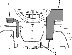
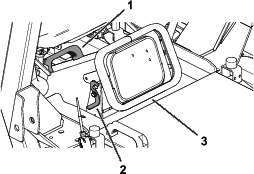
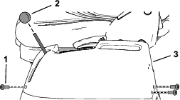
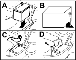
Remove the 3 socket-head screws from the left console (Figure 58).
-
Remove the throttle-lever knob (Figure 58).
-
Lift the left console up and set it aside (Figure 58).
Servicing the Battery
Danger
Battery electrolyte contains sulfuric acid which is fatal if consumed and causes severe burns.
Do not drink electrolyte and avoid contact with skin, eyes, or clothing. Wear safety glasses to shield your eyes and rubber gloves to protect your hands.
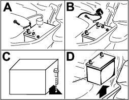
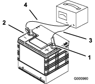
Removing the Battery
Warning
Battery terminals or metal tools could short against metal machine components causing sparks. Sparks can cause the battery gasses to explode, resulting in personal injury.
-
When removing or installing the battery, do not allow the battery terminals to touch any metal parts of the machine.
-
Do not allow metal tools to short between the battery terminals and metal parts of the machine.
Warning
Incorrect battery cable routing could damage the machine and cables causing sparks. Sparks can cause the battery gasses to explode, resulting in personal injury.
-
Always disconnect the negative (black) battery cable before disconnecting the positive (red) cable.
-
Always connect the positive (red) battery cable before connecting the negative (black) cable.
-
Park the machine on a level surface.
-
Disengage the PTO, lower the mower deck, and engage the parking brake.
-
Shut off the engine and remove the key.
-
Access the battery; refer to Accessing the Battery.
-
Remove the battery as shown in Figure 59.
Installing the Battery
Charging the Battery
Warning
Charging the battery produces gasses that can explode.
Never smoke near the battery and keep sparks and flames away from battery.
Important: Always keep the battery fully charged (1.265 specific gravity). This is especially important to prevent battery damage when the temperature is below 0°C (32°F).
-
Charge battery for 10 to 15 minutes at 25 to 30 A or 30 minutes at 10 A.
-
When the battery is fully charged, unplug the charger from the electrical outlet, then disconnect the charger leads from the battery posts (Figure 61).
-
Install the battery in the machine and connect the battery cables; refer to Installing the Battery.
Note: Do not run the machine with the battery disconnected, electrical damage may occur.
Checking the Battery Electrolyte
Note: If you store the machine in a location where temperatures are extremely high, the battery will run down more rapidly than if the machine is stored in a location where temperatures are cool.
-
Maintain the battery electrolyte concentration at a specific gravity between 1.265 to 1.299.
-
Maintain the cell level with distilled or demineralized water.
Note: Do not fill the cells above the bottom of the split ring inside each cell.
-
Clean the top of the battery periodically by performing the following:
Important: Do not remove the fill caps while cleaning the battery.
-
Wash the top of the battery with a brush dipped in ammonia or bicarbonate of soda solution.
-
Flush the top surface with clean water.
-
Servicing the Fuses
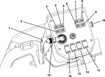
The electrical system is protected by fuses. It requires no maintenance, however, if a fuse blows check the component/circuit for a malfunction or short.
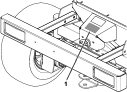
The fuse block and fuses are located to the left of the operator’s seat (Figure 62).
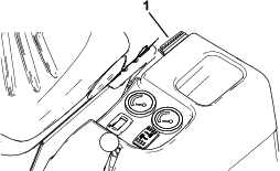
Use the following table when replacing a fuse:
| Circuit | Fuse Type |
| Security | 3 A |
| PTO | 15 A |
| Electronic control unit and buzzer | 5 A |
| Differential lock | 5 A |
| Mower deck valve and operator’s seat | 15 A |
| Alternator and dashboard | 5 A |
| Work lights, brake lights, full-beam lights, and light control unit | 15 A |
| Pull and hazard light switch, spark plugs, and key switch | 30 A |
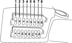
| Circuit | Fuse Type |
| Right steady light and plate light | 3 A |
| Left steady light | 3 A |
| Full-beam light | 15 A |
| Headlight | 10 A |
| Warning device | 10 A |
| Indicator lights | 7.5 A |
| Rotating beacon light | 5 A |
| Hazard-light switch | 15 A |
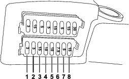
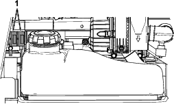
There are also 2 fuses (40 A) that protect the main machine wire harness (Figure 65).
Servicing the Wiring Harness
Prevent corrosion of wiring terminals by applying Grafo 112X (Skin-over) grease, Toro Part No. 505-47, to the inside of all harness connectors whenever you replace the harness.
Important: Whenever working with the electrical system, always disconnect the battery cables, negative (-) cable first, to prevent possible wiring damage from short-outs.
Close sectionDrive System Maintenance
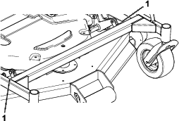
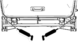
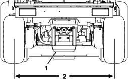
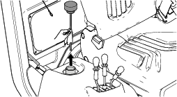
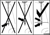
Torquing the Wheel Lug Nuts
Wheel lug nut torque specification: 85 to 90 N∙m (62 to 66 ft-lb)
Torque the lug nuts at the front and rear wheels in a crossing pattern as shown in Figure 66 to the specified torque.
Maintaining the Rear Wheel Alignment
Checking the Rear Wheel Alignment
-
Park the machine on a level surface.
-
Disengage the PTO, lower the mower deck, and engage the parking brake.
-
Shut off the engine and remove the key.
-
Rotate the steering wheel so that the rear wheels are straight ahead.
-
Measure the center-to-center distance at wheel hub height, in front and in back of the rear tires.
Note: The rear wheels should not toe-in or toe-out when they are aligned correctly.
-
If the wheels toe-in or toe-out, align the wheels; refer to Adjusting the Rear Wheel Toe-In.
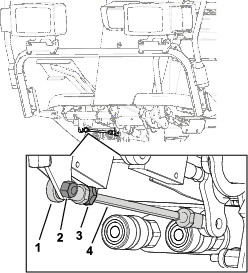
Adjusting the Rear Wheel Toe-In
-
Loosen the jam nuts at both ends of the left and right tie rods.
-
Adjust both tie rods until center-to-center distance at front and back of rear wheels is the same (Figure 67).
-
When rear wheels are adjusted correctly, tighten jam nuts against tie rods.
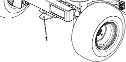
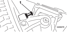
Adjusting Steering Stops
The rear-axle-steering stops help prevent over-travel of the steering cylinder in case of impact on the rear wheels. Adjust the stops so that there is 0.23 cm (0.090 inch) clearance between the bolt head and the knuckle on the axle when you turn the steering wheel completely to the left or to the right.
Thread the bolts in or out until you attain a clearance of 0.23 cm (0.090 inch); refer to Figure 68.
Cooling System Maintenance
Cooling System Safety
-
Swallowing engine coolant can cause poisoning; keep out of reach from children and pets.
-
Discharge of hot, pressurized coolant or touching a hot radiator and surrounding parts can cause severe burns.
-
Always allow the engine to cool at least 15 minutes before removing the radiator cap.
-
Use a cloth when opening the radiator cap or expansion-tank cap, and open the cap slowly to allow steam to escape.
-
Coolant Specification
Cooling system capacity: 7.5 L (8 US qt)
Coolant-type specification:
| Recommended Coolant |
|
Note: Coolant must meet or exceed ASTM Standard 3306 |
| Glycol based pre-diluted coolant (50/50 blend) |
| or |
| Glycol based coolant mixed with distilled water (50/50 blend) |
| or |
| Glycol based coolant mixed with good quality water (50/50 blend) |
| CaCO3 + MgCO3 <170 ppm |
| Chloride <40 ppm (CI) |
| Sulfer <100 ppm (SO4) |
Checking the Cooling System and Coolant Level
Warning
If the engine has been running, the radiator will be pressurized and the coolant inside will be hot. If you remove the cap, coolant may spray out, causing severe burns.
-
Do not remove the recovery-tank cap to check coolant levels. Instead, look at the level from the side of the tank.
-
Do not remove the recovery-tank cap when the engine is hot. Allow the engine to cool for at least 15 minutes or until the radiator cap is cool enough to touch without burning your hand.
-
Check the level of the coolant in the expansion tank (Figure 69).
-
If the coolant is low, remove the expansion-tank cap and add the recommended replacement coolant as required.
Do not use water only or alcohol-based coolants.Do not overfill.
-
Install the expansion-tank cap.
Checking the Radiator Screen and Radiator for Debris
To prevent the engine from overheating, keep the radiator screen and radiator clean. Check the radiator screen and radiator for buildup of grass, dust, and debris, and if necessary, clean any debris off these parts; refer to Cleaning the Radiator Screen and Radiator.
Close sectionCleaning the Radiator Screen and Radiator
Note: If the PTO shuts off due to high engine temperature, first check the radiator screen and radiator for an excessive buildup of debris. Clean the system before operating the machine. Do not shut off the engine immediately; allow the engine to cool by running it without a load.
Clean the radiator as follows:
-
Remove the radiator screen.
-
Working from the fan side of the radiator, blow with low pressure, 172 kPa (25 psi), compressed air (do not use water). Repeat this step from the front of the radiator and again from the fan side.
-
After the radiator is thoroughly cleaned, clean out any debris that may have collected in the channel at the radiator base.
-
Clean the radiator screen and install it onto the machine.
Brake Maintenance
Adjusting the Service Brakes
After adjusting the service brakes after the first 50 hours of operation, you should need to adjust the brakes again only after considerable use.
There should be approximately an 13 mm (1/2 inch) gap from the brake pedal to the front end of the slot when the brake pedal is pressed down fully.
-
Push the brake pedal down to check if there is a sufficient gap in the front end of the slot (Figure 70).
-
Release the brake pedal.
-
If an adjustment is necessary, loosen the front and rear jam nuts on each side of the brake cables (Figure 71).
-
Push the brake pedal down and move the brake cables forward or rearward.
-
Tighten the jam nuts to lock the cable positions.
-
Repeat steps 3 through 5 until you set the brake pedal to the desired position.
Belt Maintenance
Checking the Condition of the Alternator Belt
Check alternator belt for wear or damage.
Note: Replace the alternator belt if you find it worn or damaged.
Close sectionTensioning the Alternator Belt
-
Park the machine on a level surface.
-
Disengage the PTO, lower the mower deck, and engage the parking brake.
-
Shut off the engine and remove the key.
-
Access the engine from the left side; refer to Accessing the Engine from the Left Side.
-
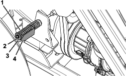
Loosen the alternator pivot bolt and lock bolt (Figure 72).
-
Tension the alternator belt until you achieve 10 mm (3/8 inch) belt deflection midway between the pulleys with a force of 4.5 kg (10 lb).
-
Tighten the alternator lock bolt (Figure 72).
-
Tighten the alternator pivot bolt (Figure 72).
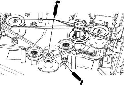
Servicing the PTO Belts
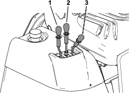
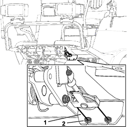
Checking the PTO Belt Tension
-
Park the machine on a level surface.
-
Disengage the PTO, lower the mower deck, and engage the parking brake.
-
Shut off the engine and remove the key.
-
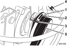
Loosen or tighten the jam nut until the tension indicator arrow aligns with the outer surface of the washer (Figure 73).
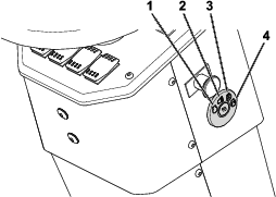
Replacing the PTO Belts
-
Park the machine on a level surface.
-
Disengage the PTO, lower the mower deck, and engage the parking brake.
-
Shut off the engine and remove the key.
-
Loosen the jam nut (Figure 73).
-
Using a 1/2-inch wrench, loosen the belt-tensioning spring (Figure 73) all the way.
-
Rotate the PTO pulley toward the engine and remove the belts.
-
Install the new PTO belts and tension the pulley spring until the tension indicator arrow aligns with the outer surface of the washer (Figure 73).
Controls System Maintenance
Adjusting the PTO Clutch Gap
-
Park the machine on a level surface.
-
Disengage the PTO, lower the mower deck, and engage the parking brake.
-
Raise and secure the hopper; refer to Raising the Hopper and Securing the Hopper in the Raised Position.
-
Shut off the engine and remove the key.
-
Open the engine-access cover; refer to Accessing the Engine from the Engine-Access Cover.
-
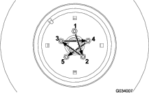
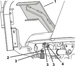
Adjust the air gap so that a 0.4 mm (0.015 inch) feeler gauge slides in between the clutch lining and friction plate with light pressure (Figure 74).
Note: You can decrease the gap by turning the adjusting nut clockwise (Figure 74). The maximum service gap is 0.7 mm (0.030 inch). Adjust all 3 air gaps.
-
After all 3 gaps have been set, check all 3 again.
Note: Adjusting 1 gap can alter the other gaps.
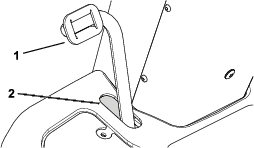
Adjusting the Traction Pedal
Adjusting the Traction-Pedal Stop
You can adjust the traction pedal for operator comfort or to reduce or increase the maximum forward speed of the machine.
You can also adjust the traction pedal to reduce or increase the maximum reverse speed of the machine.
-
Move the traction pedal fully forward (Figure 75) .
For maximum speed, there should be a 3 mm (1/8 inch) gap between the traction pedal and the traction-pedal stop.
-
If you want to reduce the forward speed of the machine, perform the following:
-
Using a wrench, hold the forward traction-pedal stop and loosen the jam nut on the back side of the bracket (Figure 75).
-
Move the traction pedal to the desired position (Figure 75).
-
Adjust the jam nut on the back of the bracket until traction-pedal stop contacts the traction pedal (Figure 75).
Note: Shortening the traction-pedal stop position will increase the forward speed of the machine.
-
While holding the traction-pedal stop, torque the jam nut at the front of the bracket to 37 to 45 N∙m (27 to 33 ft-lb).
-
Adjusting the Traction Rod
If more adjustment is required, adjust the traction rod (Figure 76) as follows:
-
Park the machine on a level surface.
-
Disengage the PTO, lower the mower deck, and engage the parking brake.
-
Shut off the engine and remove the key.
-
Remove the bolt and nut securing traction rod end to the pedal.
-
Loosen the jam nut securing rod end to the traction rod (Figure 76).
-
Rotate the rod until you achieve the desired length.
-
Tighten the jam nut (Figure 76) and secure the rod end to the traction pedal with the bolt and nut removed to lock the angle of the foot pedal.
Hydraulic System Maintenance
Hydraulic System Safety
-
Ensure that all hydraulic-fluid hoses and lines are in good condition and all hydraulic connections and fittings are tight before applying pressure to the hydraulic system.
-
Keep your body and hands away from pinhole leaks or nozzles that eject high-pressure hydraulic fluid.
-
Use cardboard or paper to find hydraulic leaks.
-
Safely relieve all pressure in the hydraulic system before performing any work on the hydraulic system.
-
Seek immediate medical attention if fluid is injected into skin. Injected fluid must be surgically removed within a few hours by a doctor.
Hydraulic Fluid Specification
The machines reservoir is filled at the factory with high quality hydraulic fluid.
Hydraulic system capacity: 6.0 L (6.3 US qt)
Hydraulic fluid type specification:
| Toro Premium Transmission/Hydraulic Tractor Fluid (Available in 5 gallon pails or 55 gallon drums. See parts catalog or Toro distributor for part numbers.) |
Alternate fluids: If the Toro fluid is not available, you may use other petroleum-based Universal Tractor Hydraulic Fluids (UTHF) provided that the specifications fall within the listed range for all the following material properties and that it meets industry standards. We do not recommend the use of synthetic fluid. Consult with your lubricant distributor to identify a satisfactory product.
Note: Toro does not assume responsibility for damage caused by improper substitutions, so use products only from reputable manufacturers who will stand behind their recommendation.
| Material Properties: | |||
| Viscosity, ASTM D445 | cSt @ 40°C 55 to 62cSt @ 100°C 9.1 to 9.8 | ||
| Viscosity Index ASTM D2270 | 140 to 152 | ||
| Pour Point, ASTM D97 | -35°F to -46°F | ||
| Industry Specifications: | |||
| API GL-4, AGCO Powerfluid 821 XL, Ford New Holland FNHA-2-C-201.00, Kubota UDT, John Deere J20C, Vickers 35VQ25, and Volvo WB-101/BM | |||
Note: Many hydraulic fluids are almost colorless, making it difficult to spot leaks. A red dye additive for the hydraulic fluid is available in 20ml (2/3fl oz) bottles. A bottle is sufficient for 15 to 22 L (4 to 6 US gallons) of hydraulic fluid. Order Part No. 44-2500 from your authorized Toro distributor.
Close sectionServicing the Hydraulic System
Preparing to Service the Hydraulic System
-
Park the machine on a level surface.
-
Disengage the PTO, lower the mower deck, and engage the parking brake.
-
Place all controls in the NEUTRAL position and start the engine.
-
Run the engine at lowest possible engine speed to purge the system of air.
Important: Do not run the PTO.
-
Cycle the steering wheel several times fully to the left and right, and align the steering wheels straight forward.
Checking the Hydraulic-Fluid Level
-
Raise the deck to retract the deck-lift cylinders, shut off the engine, and remove the key.
-
Remove the dipstick from hydraulic tank and wipe the dipstick with a clean cloth (Figure 77).
-
Insert the dipstick into the fill tube and thread the dipstick cap onto the tube.
-
Remove the dipstick and check the fluid level (Figure 78).
-
If the fluid level does not show on the dipstick, add the specified hydraulic fluid into the fill tube (Figure 79) until the fluid level can be seen on the lower 1/4 inch (6mm) of the dipstick.
Important: Do not fill the hydraulic tank with hydraulic fluid above the 6.4 mm (1/4 inch) dimension on the dipstick.
-
Thread the dipstick fill cap onto the filler tube.
Note: Do not tighten the cap with a wrench.
-
Check all hoses and fittings for leaks.
Changing the Hydraulic Fluid And Filter
Hydraulic-fluid capacity: approximately 5.6 L (6 US qt)
-
Park the machine on a level surface.
-
Disengage the PTO, lower the mower deck, and engage the parking brake.
-
Shut off the engine and remove the key.
-
Rotate the radiator to access the filter; refer to Accessing the Engine from the Right side
-
Replace the hydraulic filter as shown in Figure 80.
-
Add the specified hydraulic fluid into the fill tube until the fluid level shows at the midpoint between the upper and lower marks of the dipstick (Figure 78).
Important: Do not fill the hydraulic tank with hydraulic fluid above the 6.4 mm (1/4 inch) dimension on the dipstick.
-
Start the engine, cycle the steering wheel and deck-lift cylinders, and check for fluid leaks. Allow the engine to run for about 5 minutes, then shut it off.
-
After 2 minutes, check the level of the hydraulic fluid; refer to Checking the Hydraulic-Fluid Level.
Rotating the Mower Deck into the Maintenance Position
-
Park the machine on a level surface.
-
Disengage the PTO, lower the mower deck, and engage the parking brake.
-
Raise the hopper and engage the magnetic safety locks; refer to Securing the Hopper in the Raised Position.
-
Unlatch and remove the grass chute; refer to Clearing the Grass Chute.
-
Pull and rotate the rear link pins on both sides of the mower deck.
-
Raise the mower deck.
-
Shut off the engine and remove the key.
-
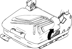
Using the handle and foot peg on the left side of the mower deck, rotate the front of the mower deck upward to the maintenance position.
Rotating the Mower Deck into the Mowing Position
Important: Ensure that you remove the grass chute before performing this procedure; otherwise, damage may occur.
-
Park the machine on a level surface.
-
Lower the mower deck.
-
Rotate the rear link pins to release them into the rear links.
-
Insert the grass chute, rotate the operator’s seat, and lower the hopper.
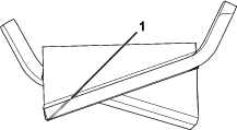
Servicing the Cutting Blades
To ensure a superior quality of cut, keep the blades sharp. For convenient sharpening and replacement, you may want to keep extra blades on hand.
Blade Safety
A worn or damaged blade can break, and a piece of the blade could be thrown toward you or bystanders, resulting in serious personal injury or death. Trying to repair a damaged blade may result in discontinued safety certification of the product.
-
Inspect the blades periodically for wear or damage.
-
Use care when checking the blades. Wrap the blades or wear gloves, and use caution when servicing the blades. Only replace or sharpen the blades; never straighten or weld them.
-
On multi-bladed machines, take care as rotating 1 blade can cause other blades to rotate.
Before Inspecting or Servicing the Blades
Prepare the mower deck for maintenance; refer to Rotating the Mower Deck into the Maintenance Position.
Close sectionInspecting the Blades
-
Inspect the cutting edges (Figure 81).
-
If the edges are not sharp or have nicks, remove and sharpen the blade; refer to Sharpening and Balancing the Blades.
-
Inspect the blades, especially in the sail area.
-
If you notice any cracks, wear, or a slot forming in this area, immediately install a new blade (Figure 81).
Removing the Blades
Removing the Center Blade
Blades must be replaced if a solid object is hit, if the blade is out of balance, or if the blade is bent. To ensure optimum performance and continued safety conformance of the machine, use genuine Toro replacement blades. Replacement blades made by other manufacturers may result in nonconformance with safety standards.
-
Hold the blade end using a cloth or a thickly padded glove.
-
Remove the blade bolt, blade retainer, spring lock washer, curved washer, and blade from the spindle shaft (Figure 82).
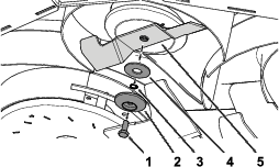
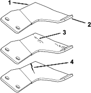
Removing the Wing Blade Assembly
Blades must be replaced if a solid object is hit, if the blade is out of balance, or if the blade is bent. To ensure optimum performance and continued safety conformance of the machine, use genuine Toro replacement blades. Replacement blades made by other manufacturers may result in nonconformance with safety standards.
The right and left blade assemblies rotate in opposite directions and are unique to their positions. Ensure that the appropriate fan discs and blades are installed in the correct positions.
-
Hold the wing blade assembly using a cloth or a thickly padded glove.
-
Remove the blade bolt, spring lock washer, blade retainer, and curved washer from the spindle shaft (Figure 83).
-
Remove the blade assembly (Figure 83).
Important: The right blade assembly blade bolt has a left-handed thread. Turn the blade bolt counterclockwise to loosen it.
Sharpening and Balancing the Blades
Sharpening and Balancing the Center Blade
-
Use a file or sharpening tool to sharpen the cutting edge at both ends of the blade (Figure 84).
Note: Maintain the original angle.
Note: The blade retains its balance if the same amount of material is removed from both cutting edges.
-
Check the balance of the blade by putting it on a blade balancer (Figure 85).
Note: If the blade stays in a horizontal position, the blade is balanced and can be used.
Note: If the blade is not balanced, file some metal off the heavy end of the blade in the sail area only (Figure 84).
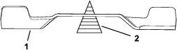
-
Repeat this procedure until the blade is balanced.
Sharpening and Balancing the Wing Blades
-
Use a file or sharpening tool to sharpen the cutting edge at both ends of the blade assembly (Figure 86).
Note: Maintain the original angle.
Note: The blade retains its balance if the same amount of material is removed from both cutting edges.
-
Check the balance of the blade assembly by putting it on a blade balancer (Figure 87).
Note: If the blade assembly stays in a horizontal position, the blade assembly is balanced and can be used.
Note: If the blade assembly is not balanced, file some metal off the heavy end of the blade in the sail area only (Figure 86).

-
Repeat this procedure until the blade assembly is balanced.
Installing the Blades
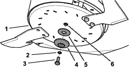
Installing the Center Blade
Blades must be replaced if a solid object is hit, if the blade is out of balance, or if the blade is bent. To ensure optimum performance and continued safety conformance of the machine, use genuine Toro replacement blades. Replacement blades made by other manufacturers may result in nonconformance with safety standards.
-
Hold the blade end using a cloth or a thickly padded glove.
-
Install the blade using the previously removed blade bolt, blade retainer, spring lock washer, and curved washer (Figure 88).
Important: The sail area of the blade must be pointing upward toward the inside of the mower to ensure proper cutting.
-
Torque the blade bolt to 53 N∙m (39 ft-lb).
Installing the Wing Blade Assembly
Important: The right blade assembly blade bolt has a left-handed thread. Ensure that you turn the blade bolt in the proper direction; otherwise, you could cause damage.
Blades must be replaced if a solid object is hit, if the blade is out of balance, or if the blade is bent. To ensure optimum performance and continued safety conformance of the machine, use genuine Toro replacement blades. Replacement blades made by other manufacturers may result in nonconformance with safety standards.
-
Hold the wing blade assembly using a cloth or a thickly padded glove.
-
Install the wing blade assembly using the previously removed disc bolt, spring lock washer, blade retainer, and curved washer (Figure 89).
Important: The sail area of the blades must be pointing upward toward the inside of the mower to ensure proper cutting.
-
Torque the disc bolt to 53 N∙m (39 ft-lb).
-
Torque the blade bolts to 50 N∙m (37 ft-lb).
Removing the Mower Deck
-
Park the machine on a level surface.
-
Disengage the PTO, lower the mower deck, and engage the parking brake.
-
Tilt the hopper back.
-
Shut off the engine and remove the key.
-
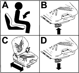
Tilt the seat forward.
-
Remove the grass chute; refer to Clearing the Grass Chute.
-
Disconnect the hydraulic hoses from each side of the traction unit.
-
Pull and rotate the rear link pins on both sides of the mower deck.
-
Disconnect the forward end of the drive shaft from the mower deck gearbox by pressing the spring-loaded pin, and then pulling the end of the drive shaft rearward.
-
Remove the lynch pin and clevis pin securing the lift arms on each side.
-
Roll the mower deck forward and away from the traction unit.
Installing the Mower Deck
-
Park the machine on a level surface.
-
Tilt the hopper back.
-
Shut off the engine and remove the key.
-
Remove the grass chute; refer to Clearing the Grass Chute.
-
Roll the mower deck rearward to the traction unit.
-
Install the lynch pin and clevis pin to secure the lift arms on each side.
-
Connect the forward end of the drive shaft to the mower deck gearbox by pressing the spring-loaded pin, and then push the end of the drive shaft forward.
-
Connect the hydraulic hoses on each side of the traction unit.
-
Install the grass chute.
-
Tilt the seat rearward.
-
Start the engine.
-
Lower the hopper.
-
Raise the mower deck.
-
Rotate the rear link pins to engage the mower deck rear lift links.
Checking the Mower Deck Belt Tension
-
Park the machine on a level surface.
-
Disengage the PTO, lower the mower deck, and engage the parking brake.
-
Shut off the engine and remove the key.
-
Loosen or tighten the jam nut until the tension indicator arrow aligns with the outer surface of the washer (Figure 90).
Switching the Skids
When the skids wear out, you can switch them to the other side of the mower deck to gain additional use.
-
Park the machine on a level surface.
-
Disengage the PTO and engage the parking brake.
-
Rotate the mower deck to the maintenance position; refer to Rotating the Mower Deck into the Maintenance Position.
-
Shut off the engine and remove the key.
-
Remove the skids from the sides of the mower deck.
-
Switch the skids and install them using the previously removed screws.
Important: Use only the top 2 sets of holes when you install the skids.
Cleaning Under the Mower Deck Belt Cover
-
Disengage the blade-control switch (PTO) and engage the parking brake.
-
Shut off the engine, remove the key, and wait for all moving parts to stop before leaving the operating position.
-
Insert an air nozzle in the gap between the belt cover and the top of the mower deck. Use compressed air to clear any accumulated grass from under the mower deck belt cover.
Cleaning Under the Mower Deck
-
Disengage the blade-control switch (PTO) and engage the parking brake.
-
Shut off the engine, remove the key, and wait for all moving parts to stop before leaving the operating position.
-
Prepare the mower deck for maintenance; refer to Rotating the Mower Deck into the Maintenance Position.
-
Remove any packed grass or debris, and clean as necessary.
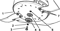
Cleaning the Hopper Screen
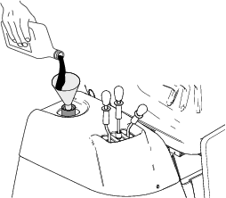
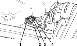
-
Open the hopper door.
-
Pull the release lever on the bottom of the hopper screen downward (Figure 91).
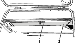
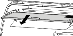
-
Remove the hopper screen and clean it (Figure 92).
-
Install the hopper screen.
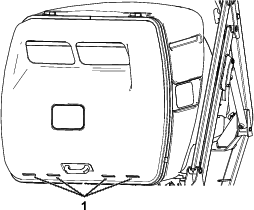
Cleaning the Rear Slots in the Hopper Door
-
Disengage the blade-control switch (PTO) and engage the parking brake.
-
Shut off the engine, remove the key, and wait for all moving parts to stop before leaving the operating position.
-
Using compressed air, clear the grass and debris from the lower, rear slots in the hopper door (Figure 93).
Disposing of Waste
Engine oil, batteries, hydraulic fluid, and engine coolant are pollutants to the environment. Dispose of these according to your state and local regulations.
Close section