CALIFORNIA
Proposition 65 Warning
 |
Safety decals and instructions are easily visible to the operator and are located near any area of potential danger. Replace any decal that is damaged or missing. |

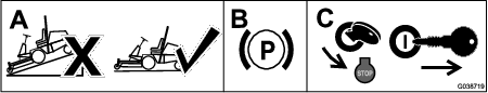
Park the machine on a level surface.
Engage the parking brake.
Shut off the engine and remove the key.
Parts needed for this procedure:
| Switch | 1 |
| Auxiliary-brake decal | 1 |
Remove the 6 bolts from the side panel and remove the side panel from the console (Figure 3).
Note: Retain and set aside the bolts.
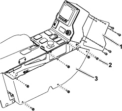
Remove the 4 bolts from the back panel and remove the back panel from the console (Figure 3).
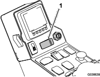
Remove the plug from the control panel and install the switch (Figure 4).
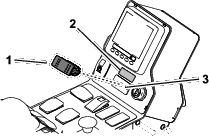
Adhere the auxiliary-brake decal above the switch (Figure 4).
Parts needed for this procedure:
| Wire harness | 1 |
Connect the new wire harness to the auxiliary-brake switch (Figure 5).
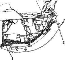
Connect the wire harness to the EU light power connector inside the console (Figure 5).
Use the previously removed bolts to install the back and side panels to the console (Figure 3).
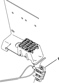
Following the existing wire harness, route the section of the wire harness with the ring-terminal connector through the hole in the electrical cover plate, behind the seat.
Secure the ring-terminal connector to an empty terminal on the ground block (Figure 6).
Contact your authorized Toro distributor to enable the braking system.
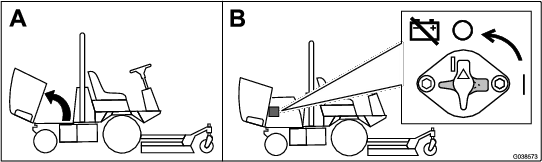
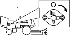
Close sectionPress and hold the auxiliary-brake switch to decrease the engine speed (Figure 8); release the switch to stop the deceleration and remain at the current engine speed.
Note: You may use the switch intermittently to gradually slow the machine.
If you press the switch when the engine speed is below 1,200 rpm or if the engine decelerates to 1,200 rpm, the engine shuts off and the machine stops. To start the machine again:
Turn the key switch to the STOP position.
Turn the key switch to the START position.
Note: Immediately release the key switch when the engine starts.