
 , which means Caution, Warning, or Danger—personal safety instruction. Failure to comply with the instruction
may result in personal injury or death.
, which means Caution, Warning, or Danger—personal safety instruction. Failure to comply with the instruction
may result in personal injury or death.


Maintenance
Note: Determine the left and right sides of the machine from the normal operating position.
Recommended Maintenance Schedule(s)
| Maintenance Service Interval | Maintenance Procedure |
|---|---|
| After the first 10 hours |
|
| Before each use or daily |
|
| Every 25 hours |
|
| Every 40 hours |
|
| Every 50 hours |
|
| Every 100 hours |
|
| Every 300 hours |
|
Important: Refer to your engine owner's manual for additional maintenance procedures.
Pre-Maintenance Procedures
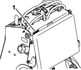
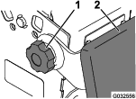
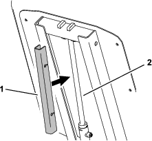
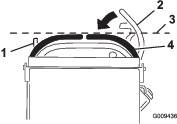
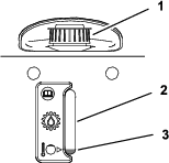
Releasing the Cushion for Rear Access
You can release the cushion for rear access to the machine for maintenance or adjustment.
-
Lower the platform.
-
Loosen the twist knobs on each side of the machine (Figure 16).
-
Remove the cushion and lower it to the platform.
-
Perform any maintenance or adjustment on the machine.
-
Raise the cushion, and slide it onto the pins on both sides of the machine.
-
Tighten the twist knobs.
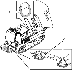
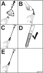
Using the Cylinder Lock
Installing the Cylinder Lock
-
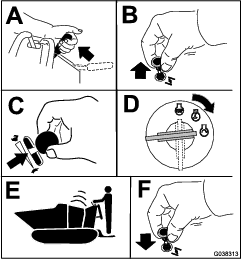
Park the machine on a level surface, move the motion-control levers to the NEUTRAL-LOCK position, engage the parking brake, and fully raise the hopper.
-
Remove the 2 cotterless pins securing the cylinder lock to the machine.
-
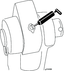
Slide the cylinder lock over the lift-cylinder rod and secure with the cotterless pins (Figure 17).
-
Slowly lower the hopper until the cylinder lock contacts the cylinder body and rod end.
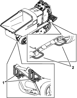
Removing and Storing the Cylinder Lock
Important: Remove the cylinder lock from the lift-cylinder rod and fully secure it in the storage position before operating the machine.
-
Start the machine.
-
Fully raise the hopper.
-
Shut off the engine.
-
Remove the cotterless pins securing the cylinder lock.
-
Place the cylinder lock on the posts inside the machine frame and secure with the cotterless pins.
-
Lower the hopper.
Lubrication
Greasing the Machine
| Maintenance Service Interval | Maintenance Procedure |
|---|---|
| Every 50 hours |
|
When operating the machine under normal conditions, lubricate all grease fittings for the bearings and bushings with No. 2 lithium grease. Lubricate the bearings and bushings immediately after every washing, regardless of the interval listed. Apply a light coating of oil onto the control cables.
Cylinder pivots (2)—Figure 18
Engine Maintenance
Servicing the Air Cleaner
| Maintenance Service Interval | Maintenance Procedure |
|---|---|
| Every 25 hours |
|
| Every 100 hours |
|
Note: Operating the engine with loose or damaged air-cleaner components could allow unfiltered air into the engine, causing premature wear and failure.
Note: Service the air cleaner more often under extremely dusty, dirty conditions.
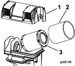
Removing the Elements
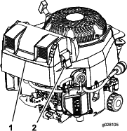
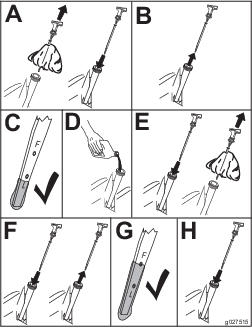
Servicing the Foam Element
-
Wash the foam element in warm water and detergent.
-
Rinse and allow it to air dry.
-
Lightly oil the foam element with new oil and squeeze out excess oil.
Servicing the Paper Element
-
Gently tap the paper element to dislodge dirt.
Note: Do not wash the paper element or use pressurized air, as this damages the element.
Note: Replace a dirty, bent, or damaged element. Handle the new element carefully; do not use if the sealing surfaces are bent or damaged.
-
Clean the air-cleaner base as required, and check the condition.
Checking the Engine-Oil Level
| Maintenance Service Interval | Maintenance Procedure |
|---|---|
| Before each use or daily |
|
Important: Remember to add 80% of the oil, and then gradually fill it to the Full mark on the dipstick.
Important: Do not run the engine with the oil level above the Full mark or below the low mark. Otherwise, you may damage the engine.
-
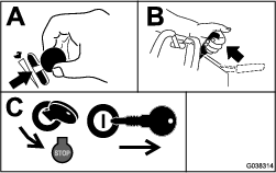
Park the machine on a level surface, move the motion-control levers to the NEUTRAL-LOCK position, engage the parking brake, and lower the hopper.
-
Shut off the engine, and remove the key. Allow the engine to cool.
-
Open the cowl.
-
Check the engine-oil level as shown in Figure 21.
Changing the Engine Oil and Filter
| Maintenance Service Interval | Maintenance Procedure |
|---|---|
| Every 100 hours |
|
Oil Type:: Detergent oil (API service SJ or higher)
Engine Oil Capacity: 1.9 L (2.0 US quarts)
Viscosity: Refer to the table below.
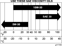
Note: Dispose of the used oil at a recycling center.
-
Park the machine on a level surface, move the motion-control levers to the NEUTRAL-LOCK position, engage the parking brake, raise the hopper, and install the cylinder lock.
-
Shut off the engine, and remove the key. Allow the engine to cool.
-
Start and run engine for a few minutes to warm the engine oil, then shut off the engine.
-
Change the engine oil as shown in Figure 23.
-
Torque the plug to 13.6 N∙m (10 ft-lb).
-
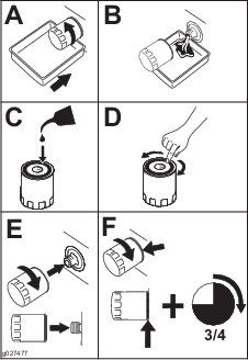
Change the engine-oil filter as shown in Figure 24.
-
Slowly pour approximately 80% of the specified oil into the filler tube (Figure 25).
Servicing the Spark Plugs
| Maintenance Service Interval | Maintenance Procedure |
|---|---|
| Every 100 hours |
|
| Every 300 hours |
|
The spark plugs are RFI compliant. Equivalent alternate brand plugs can also be used.
Type: Champion XC12YC
Air Gap: 0.76 mm (0.03 inch)
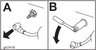
Removing the Spark Plug
-
Park the machine on a level surface, move the motion-control levers to the NEUTRAL-LOCK position, engage the parking brake, and lower the hopper.
-
Shut off the engine and remove the key. Allow the engine to cool.
-
Before removing the spark plug(s), clean the area around the base of the plug to keep dirt and debris out of the engine.
-
Remove the spark plug (Figure 26).
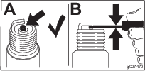
Checking the Spark Plug
Important: Do not clean the spark plug(s). Always replace the spark plug(s) when it has: a black coating, worn electrodes, an oily film, or cracks.
Note: If you see light brown or gray on the insulator, the engine is operating properly. A black coating on the insulator usually means the air cleaner is dirty.
Set the gap to 0.76 mm (0.03 inch).
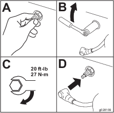
Installing the Spark Plug
Cleaning the Blower Housing
| Maintenance Service Interval | Maintenance Procedure |
|---|---|
| Before each use or daily |
|
| Every 100 hours |
|
To ensure proper cooling, ensure that the grass screen, cooling fins, and other external surfaces of the engine are kept clean at all times.
Ensure that the cooling shrouds are installed.
Important: Operating the engine with a blocked grass screen, dirty or plugged cooling fins, and/or cooling shrouds removed causes engine damage due to overheating.
Fuel System Maintenance
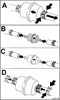
Replacing the Fuel Filter
| Maintenance Service Interval | Maintenance Procedure |
|---|---|
| Every 100 hours |
|
-
Park the machine on a level surface, move the motion-control levers to the NEUTRAL-LOCK position, engage the parking brake, and lower the hopper.
-
Shut off the engine, and remove the key. Allow the engine to cool.
-
Replace the fuel filter as shown in Figure 29.
Draining the Fuel Tank
You can drain the fuel tank by removing it and pouring the fuel out of the fill neck; refer to Removing the Fuel Tank. You can also drain the fuel tank by using a siphon in the following procedure.
Danger
In certain conditions, fuel is extremely flammable and highly explosive. A fire or explosion from fuel can burn you and others and can damage property.
-
Drain fuel from the fuel tank when the engine is cold. Do this outdoors in an open area. Wipe up any fuel that spills.
-
Never smoke when draining fuel and stay away from an open flame, or where a spark may ignite the fuel fumes.
-
Park the machine on a level surface, move the motion-control levers to the NEUTRAL-LOCK position, engage the parking brake, and lower the hopper.
-
Shut off the engine, and remove the key. Allow the engine to cool.
-
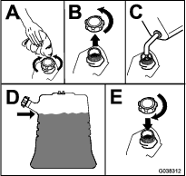
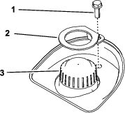
Clean around the fuel cap to prevent debris from getting into the fuel tank (Figure 30).
-
Remove the fuel cap.
-
Insert a syphon pump into the fuel tank.
-
Using the syphon pump, drain the fuel into a clean fuel can (Figure 30).
-
Wipe up any spilled fuel.
Removing the Fuel Tank
-
Lower the platform.
-
Release the cushion; refer to Releasing the Cushion for Rear Access.
-
Remove the cross bracket (Figure 31).
-
Remove the fuel tank and set it on the operator platform.
Note: If you want to move the fuel tank further from the machine, remove the fuel and vent lines from the top of the tank.
Electrical System Maintenance
Servicing the Battery
| Maintenance Service Interval | Maintenance Procedure |
|---|---|
| Every 50 hours |
|
Warning
CALIFORNIA
Proposition 65 Warning
Use of this product may cause exposure to chemicals known to the State of California to cause cancer, birth defects, or other reproductive harm.
Danger
Battery electrolyte contains sulfuric acid, which is fatal if consumed and causes severe burns.
Do not drink electrolyte and avoid contact with skin, eyes or clothing. Wear safety glasses to shield your eyes and rubber gloves to protect your hands.
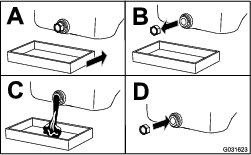
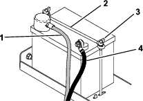
Removing the Battery
Warning
Battery terminals or metal tools could short against metal machine components, causing sparks. Sparks can cause the battery gasses to explode, resulting in personal injury.
-
When removing or installing the battery, do not allow the battery terminals to touch any metal parts of the machine.
-
Do not allow metal tools to short between the battery terminals and metal parts of the machine.
Warning
Incorrect battery-cable routing could damage the machine and cables, causing sparks. Sparks can cause the battery gasses to explode, resulting in personal injury.
-
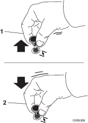
Always disconnect the negative (black) battery cable before disconnecting the positive (red) cable.
-
Always connect the positive (red) battery cable before connecting the negative (black) cable.
-
Park the machine on a level surface, move the motion-control levers to the NEUTRAL-LOCK position, engage the parking brake, and lower the hopper.
-
Shut off the engine, and remove the key. Allow the engine to cool.
-
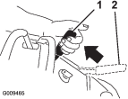
Remove the negative battery cable from the battery (Figure 32).
-
Remove the positive battery cable from the battery (Figure 32).
-
Remove the 2 wing nuts, securing rod, and the battery (Figure 32).
Installing the Battery
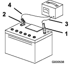
Charging the Battery
Warning
Charging the battery produces gasses that can explode.
Never smoke near the battery and keep sparks and flames away from battery.
Important: Always keep the battery fully charged (1.265 specific gravity) to prevent battery damage when the temperature is below 0°C (32°F).
-
Remove the battery from the chassis; refer to .
-
Check the electrolyte level.
-
Ensure that the filler caps are installed on the battery.
-
Charge the battery for 1 hour at 25 to 30 A or 6 hours at 4 to 6 A.
-
When the battery is fully charged, unplug the charger from the electrical outlet, and disconnect the charger leads from the battery posts (Figure 33).
-
Install the battery onto the machine and connect the battery cables; refer to .
Note: Do not run the machine with the battery disconnected; electrical damage may occur.
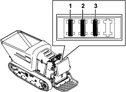
Servicing the Fuses
The electrical system is protected by fuses and requires no maintenance. If a fuse blows, check the component or circuit for a malfunction or short.
Drive System Maintenance
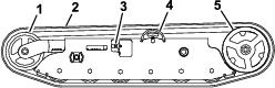
Servicing the Tracks
| Maintenance Service Interval | Maintenance Procedure |
|---|---|
| After the first 10 hours |
|
| Before each use or daily |
|
| Every 50 hours |
|
| Every 300 hours |
|
Cleaning the Tracks
-
Park the machine on a level surface, move the motion-control levers to the NEUTRAL-LOCK position, engage the parking brake, and lower the hopper.
-
Shut off the engine, and remove the key. Allow the engine to cool.
-
Lift/support the side of the machine to be worked on so that the track is 3 to 4 inches (7.6 to 10 cm) off the ground.
-
Using a water hose or pressure washer, remove dirt from each track system.
Important: Ensure that you use high-pressure water to wash only the track area. Do not use a high-pressure washer to clean the rest of the machine. Do not use high pressure water between the drive sprocket and the machine or you may damage the motor seals. High-pressure washing can damage the electrical system and hydraulic valves or deplete grease.
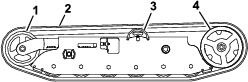
Important: Ensure that you fully clean the road wheels, the front wheel, and the drive sprocket (Figure 35). The road wheels should rotate freely when clean.
Adjusting the Track Tension
If you place the tab of the tensioning tool along the rear edge of the tension nut, the other end of the tensioning tool should align with the edge of the tension arm as shown in Figure 36. If the distance is not correct, adjust the track tension using the following procedure:
Note: If the tensioning tool is not available, the distance between the nut and edge of the tension arm should be 7.1 cm (2-13/16 inch).
-
Park the machine on a level surface, move the motion-control levers to the NEUTRAL-LOCK position, engage the parking brake, and lower the hopper.
-
Shut off the engine, and remove the key. Allow the engine to cool.
-
Clean the tracks with high-pressure water.
Important: Ensure that you use high-pressure water to wash only the track area. Do not use a high-pressure washer to clean the rest of the machine. Do not use high pressure water between the drive sprocket and the machine or you may damage the motor seals. High-pressure washing can damage the electrical system and hydraulic valves or deplete grease.
-
Clean the drive sprocket, the front wheel, and the road wheels. The road wheels should spin freely when clean.
-
Remove the bolt (1/4 x 1-5/8 inch), spacer, and nut (Figure 36).
-
Turn the tensioning bolt to adjust the distance between the tension nut and the end tangent of the tension tube until the distance is correct, as shown in Figure 36.
-
Align the closest notch in the tensioning bolt to the bolt hole and secure the tensioning bolt with the bolt (1/4 x 1-5/8 inch), spacer, and nut (Figure 36).
Replacing the Tracks
Replace the tracks when they are badly worn.
-
Park the machine on a level surface, move the motion-control levers to the NEUTRAL-LOCK position, engage the parking brake, and lower the hopper.
-
Shut off the engine, and remove the key. Allow the engine to cool.
-
Lift/support the side of the machine to be worked on so that the track is 3 to 4 inches (7.6 to 10 cm) off the ground.
-
Remove the retaining bolt for the tensioning screw.
-
Release the drive tension by turning the tensioning screw clockwise (Figure 36 and Figure 37).
-
Remove the track at the top of the front wheel, peeling it off the wheel while rotating the track forward.
-
When the track is off the front wheel, remove it from the drive sprocket and road wheels (Figure 37).
-
Beginning at the drive sprocket, coil the new track around the sprocket, ensuring that the lugs on the track fit between the spacers on the sprocket (Figure 37).
-
Push the track under the lugs and between the road wheels (Figure 37).
-
Starting at the bottom of the front wheel, install the track around the wheel by rotating the track rearward while pushing the lugs into the wheel.
-
Tension the track; refer to Adjusting the Track Tension.
-
Lower the machine to the ground.
-
Repeat steps 3 through 12 to replace the other track.
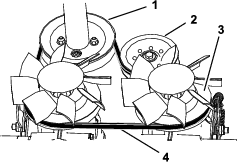
Servicing the Drive Belt
Inspecting the Drive Belt
| Maintenance Service Interval | Maintenance Procedure |
|---|---|
| Every 100 hours |
|
-
Park the machine on a level surface, move the motion-control levers to the NEUTRAL-LOCK position, engage the parking brake, and lower the hopper.
-
Shut off the engine, and remove the key. Allow the engine to cool.
-
Release the cushion and remove the fuel tank; refer to .
-
Inspect the belt (Figure 38). Replace the belt if it is worn; refer to .
Note: The signs of a worn belt include squealing while the belt is rotating, frayed edges, burn marks, and cracks on the belt.
Replacing the Drive Belt
| Maintenance Service Interval | Maintenance Procedure |
|---|---|
| Every 300 hours |
|
-
Park the machine on a level surface, move the motion-control levers to the NEUTRAL-LOCK position, engage the parking brake, and lower the hopper.
-
Shut off the engine, and remove the key. Allow the engine to cool.
-
Release the cushion and remove the fuel tank; refer to Removing the Fuel Tank.
-
Raise the rear of the machine and support the machine on jack stands.
-
Remove the skid plate (Figure 36).
-
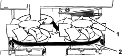
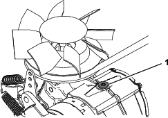
Remove the extension spring (Figure 38).
-
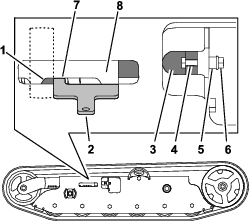
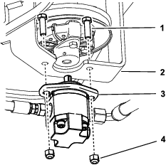
Remove the 2 bolts and 2 nuts and loosen the 2 set screws on the coupler. Remove the gear pump from the pump mount (Figure 40).
Note: You do not need to remove the fittings from the pump.
-
Remove the drive belt from the engine pulley and 2 transmission pulleys.
-
Route the new belt around the engine pulley and 2 transmission pulleys (Figure 41).
-
Install the gear pump (Figure 40).
-
Install the extension spring (Figure 38).
-
Install the fuel tank; refer to Removing the Fuel Tank.
-
Raise the cushion.
Controls System Maintenance
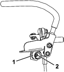
Adjusting the Motion-Control Levers
If the motion-control levers do not align horizontally, adjust the right side motion-control lever.
-
Park the machine on a level surface, lower the hopper, engage the parking brake, shut off the engine, and remove the key.
-
Push the motion-control levers down out of the NEUTRAL-LOCK position (Figure 42).
-
Check if the right motion-control lever aligns horizontally with the left motion-control lever (Figure 42).
-
To adjust the motion-control levers horizontally, you must adjust the cam.
-
Release the cushion from the rear of the machine.
-
Loosen the nut holding the cam (Figure 43).
-
Adjust the cam until it aligns with the left motion-control lever and tighten the nut for the cam.
Note: Moving the cam clockwise (in the vertical position) lowers the handle; moving the cam counterclockwise (in the vertical position) raises the handle.
Important: Ensure that the flat portion of the cam does not go above a vertical position (right or left); otherwise you may damage the switch.
-
Repeat steps 2 through 7 for the left motion-control lever.
Brake Maintenance
Warning
If the brakes are not properly adjusted, serious injury, or death, may occur.
Check your brakes daily. If you encounter any problems with the brakes while operating the machine, stop the machine immediately and bring it to an Authorized Service Dealer for repair.
Checking the Parking Brake
| Maintenance Service Interval | Maintenance Procedure |
|---|---|
| Before each use or daily |
|
-
Park the machine on a level surface, lower the hopper, and engage the parking brake.
-
Start the engine and move the throttle lever to the FAST position.
-
Move the motion-control levers forward.
Note: The machine should not move forward.
Note: If the machine moves forward, refer to Adjusting the Parking Brake.
-
Release the parking brake.
-
Move the motion-control levers forward.
Note: The machine should move forward.
Note: If the machine does not move forward, refer to Adjusting the Parking Brake.
-
Engage the parking brake and shut off the machine.
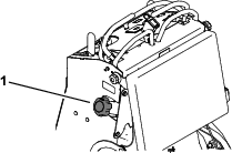
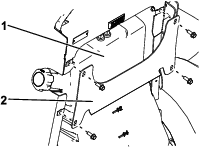
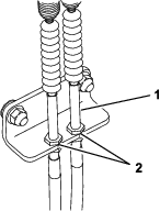
Adjusting the Parking Brake
-
Remove the fuel tank; refer to .
-
Inside the left side of the control tower, adjust the nuts until the cables are taught (Figure 44).
-
Install the fuel tank, cross bracket, and cushion.
Hydraulic System Maintenance
Warning
Hydraulic fluid escaping under pressure can penetrate skin and cause injury. Fluid injected into the skin must be surgically removed within a few hours by a doctor familiar with this form of injury; otherwise gangrene may result.
-
Keep your body and hands away from pinhole leaks or nozzles that eject high-pressure hydraulic fluid.
-
Use cardboard or paper to find hydraulic leaks; never use your hands.
Servicing the Hydraulic Drive System
Expansion-tank capacity: 1.4 L (1.5 US quarts)
Hydraulic-fluid type: Toro® HYPR-OIL™ 500
Important: Always use the correct hydraulic fluid. Unspecified fluids will damage the hydraulic system.
Note: Many hydraulic fluids are almost colorless, making it difficult to spot leaks. A red dye additive for the hydraulic system oil is available in 0.67 fl oz (20 ml) bottles. One bottle is sufficient for 4 to 6 gal (15 to 22 L) of hydraulic fluid. Order Part No. 44-2500 from your authorized Toro distributor.
Checking the Hydraulic-Fluid Level for the Drive System
| Maintenance Service Interval | Maintenance Procedure |
|---|---|
| Before each use or daily |
|
-
Park the machine on a level surface, move the motion-control levers to the NEUTRAL-LOCK position, engage the parking brake, and lower the hopper.
-
Shut off the engine, and remove the key. Allow the engine to cool.
-
Open the cowl.
-
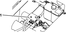
Use the sight window to check the fluid level in the expansion tank (Figure 45).
Note: The fluid level should be at the fill line on the decal.
-
If the oil level is low, remove the cap lock and cap from the top of the expansion tank (Figure 46), and add enough of the specified hydraulic fluid to raise it to the proper level.
-
Install the cap and cap lock. Wipe up any spilled hydraulic fluid.
Changing the Hydraulic Fluid and Filter for the Drive System
| Maintenance Service Interval | Maintenance Procedure |
|---|---|
| Every 300 hours |
|
-
Park the machine on a level surface, move the motion-control levers to the NEUTRAL-LOCK position, engage the parking brake, and lower the hopper.
-
Shut off the engine, and remove the key. Allow the engine to cool.
-
Lower the cushion and remove the fuel tank; refer toRemoving the Fuel Tank.
-
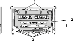
Remove the 6 bolts (2 rear, 4 side) from the skid plate and remove the skid plate (Figure 47).
-
Locate the drain plug in the bottom of each transmission, then place a drain pan under the plugs (Figure 48).
-
Remove the drain plugs and allow the hydraulic fluid to fully drain from the machine.
-
Remove the hydraulic-filter cap and hydraulic filter from each transmission (Figure 48).
-
Install a new hydraulic filter with the spring side facing out and the hydraulic-filter cap for each transmission. Torque to 13 to 15 N∙m (115 to 135 in-lb).
-
Install the drain plugs.
-
Loosen the vent plug in each transmission until loose (Figure 49).
Note: This allows air to escape the hydraulic system as you add hydraulic fluid.
-
Slowly add approximately 6.2 L (208 fl oz) fluid to the expansion tank until it starts to come out of the vent plugs.
Important: Use the fluid specified in or equivalent. Other fluids could cause system damage.
Important: Monitor the level of fluid in the expansion tank so that you do not overfill it.
-
Tighten the vent plugs.
-
Add hydraulic fluid to the expansion tank until it reaches the fluid line (Figure 45).
Important: Do not overfill.
-
Install the expansion-tank cap.
-
Install the skid plate (Figure 47).
-
Install the fuel tank; refer to Removing the Fuel Tank.
-
Start the engine and let it run for about 2 minutes to purge air from the system.
-
Shut off the engine and check for leaks.
Bleeding the Hydraulic Drive System
Bleed the traction hydraulic system whenever you perform maintenance on the hydrostatic transmission or add hydraulic fluid to the expansion tank.
-
Park the machine on a level surface, move the motion-control levers to the NEUTRAL-LOCK position, engage the parking brake, and lower the hopper.
-
Shut off the engine, and remove the key. Allow the engine to cool.
-
Check the hydraulic fluid level and add hydraulic fluid as necessary; refer to Checking the Hydraulic-Fluid Level for the Drive System.
-
Support the machine on jack stands, high enough to raise the tracks off the ground.
-
Start the machine. Slowly move the motion-control levers forward and reverse 5 to 6 times.
-
Check the hydraulic fluid level and add hydraulic fluid as necessary.
-
Repeat steps 5 and 6 as necessary until all the air is completely purged from the system.
Note: Purging is complete when you obtain normal forward and reverse speed.
-
Lower the machine and repeat the procedure with the tracks on the ground.
Servicing the Hydraulic Lift System
Checking the Hydraulic-Fluid Level for the Lift System
| Maintenance Service Interval | Maintenance Procedure |
|---|---|
| Before each use or daily |
|
Reservoir-tank capacity: 1.4 L (1.5 US quarts)
Hydraulic-fluid type: Toro Premium All Season Hydraulic Fluid or Mobil® 424 Hydraulic Fluid
Important: Always use the correct hydraulic fluid. Unspecified fluids will damage the hydraulic system.
Note: Many hydraulic fluids are almost colorless, making it difficult to spot leaks. A red dye additive for the hydraulic system oil is available in 0.67 fl oz (20 ml) bottles. One bottle is sufficient for 4 to 6 gal (15 to 22 L) of hydraulic fluid. Order Part No. 44-2500 from your authorized Toro distributor.
-
Park the machine on a level surface, move the motion-control levers to the NEUTRAL-LOCK position, engage the parking brake, raise the hopper, and install the cylinder lock.
-
Shut off the machine and remove the key. Allow the machine to cool completely.
-
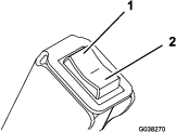
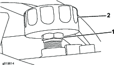
Remove the filler cap from the reservoir tank (Figure 50).
Caution
The hydraulic breather/filler cap is designed to pressurize the reservoir to 34 kPa (5 psi).
Loosen the cap slowly to avoid injury whenever adding fluid or working on the hydraulic system. Use a wrench on the hex directly under the cap.
-
Look inside the tank to check the fluid level.
Note: If the machine is cool, the fluid should be at the COLD level; if the machine is hot, the fluid should be at the HOT level.
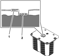
-
Fill the tank with hydraulic fluid only up to the COLD level.
-
Install the fill cap. Wipe up any spilled hydraulic fluid.
-
Remove the cylinder lock and lower the hopper.
Changing the Hydraulic Fluid for the Lift System
| Maintenance Service Interval | Maintenance Procedure |
|---|---|
| Every 300 hours |
|
-
Park the machine on a level surface, move the motion-control levers to the NEUTRAL-LOCK position, engage the parking brake, raise the hopper, and install the cylinder lock.
-
Shut off the machine and remove the key. Allow the machine to cool completely.
-
Remove the filler cap from the reservoir tank (Figure 50).
Caution
The hydraulic breather/filler cap is designed to pressurize the reservoir to 34 kPa (5 psi).
Loosen the cap slowly to avoid injury whenever adding oil or working on the hydraulic system. Use a wrench on the hex directly under the cap.
-
Place a large drain pan under the fittings at the bottom of the reservoir tank.
-
Disconnect a hose fitting and allow the fluid to drain into the pan.
-
When finished, install and tighten the fitting.
Note: Dispose of the used fluid at a certified recycling center.
-
Fill the reservoir tank with approximately 2.2 L (2.3 US quarts) and install the filler cap.
-
Remove the cylinder lock.
-
Start the engine. Raise and lower the hopper 3 times to fill the cylinder and hoses with fluid.
-
Raise the hopper and install the cylinder lock.
-
Shut off the engine.
-
Add 0.60 L (20 fl oz) of hydraulic fluid and install the filler cap.
Note: The fluid level should be at the Cold fill line. Do not fill past this line.
-
Remove the cylinder lock.
-
Start the engine. Raise and lower the hopper several times to remove air from the system.
Replacing the Hydraulic Filter for the Lift System
| Maintenance Service Interval | Maintenance Procedure |
|---|---|
| Every 300 hours |
|
Important: Do not substitute an automotive oil filter or severe hydraulic system damage may result.
-
Park the machine on a level surface, move the motion-control levers to the NEUTRAL-LOCK position, engage the parking brake, raise the hopper, and install the cylinder lock.
-
Shut off the engine, and remove the key. Allow the engine to cool.
-
Replace the filter as shown in Figure 52.
-
Start the engine and let it run for about 2 minutes to purge air from the system.
-
Shut off the engine and check for leaks.
-
Check the fluid level in the reservoir tank, refer to .
Note: Do not overfill the reservoir tank.
-
Remove the cylinder lock and lower the hopper.
Checking the Hydraulic Lines
| Maintenance Service Interval | Maintenance Procedure |
|---|---|
| Every 40 hours |
|
Warning
Hydraulic fluid escaping under pressure can penetrate skin and cause injury. Fluid injected into the skin must be surgically removed within a few hours by a doctor familiar with this form of injury; otherwise, gangrene may result.
-
Keep your body and hands away from pinhole leaks or nozzles that eject high-pressure hydraulic fluid.
-
Use cardboard or paper to find hydraulic leaks; never use your hands.
Cleaning
Removing Debris from the Machine
| Maintenance Service Interval | Maintenance Procedure |
|---|---|
| Before each use or daily |
|
| Every 100 hours |
|
-
Park the machine on a level surface, move the motion-control levers to the NEUTRAL-LOCK position, engage the parking brake, and lower the hopper.
-
Shut off the engine, and remove the key. Allow the engine to cool.
-
Clean the inside of the hopper using a hose.
-
Clean any debris from under the hopper.
-
Wipe away debris from the air cleaner.
-
Clean any debris buildup on the engine and in the transmission with a brush or blower.
Important: It is preferable to blow dirt out, rather than washing it out. If you use water, keep it away from electrical parts and hydraulic valves. Do not use a high-pressure washer. High-pressure washing can damage the electrical system and hydraulic valves or deplete grease.