Parts needed for this procedure:
| Steering wheel | 1 |
| Roll pin | 1 |
| Spacer | 1 |
| Cap | 1 |
Position the front wheels straight ahead.
Install the plastic spacer over the steering wheel shaft (smaller diameter first).
Slide the steering wheel over the shaft, aligning the holes on each side of the steering wheel with the holes in the spacer and with the holes in the shaft.
Drive the roll pin through the holes in the steering wheel, the plastic spacer, and the shaft with a hammer to secure the steering wheel.
Place the cap onto the steering wheel.
Parts needed for this procedure:
| Seat | 1 |
| Bolts | 2 |
| Adjusting knob | 2 |
| Spacers | 2 |
| Spring washers | 2 |
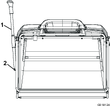
Remove the plastic cover from the seat and discard it.
Set the seat in place and secure it with the 2 bolts, and 2 spacers (Figure 1).
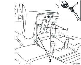
Install the 2 adjusting knobs and 2 spring washers (Figure 1).
Ensure that the safety switch is connected to the seat (Figure 1).
Parts needed for this procedure:
| Collector cover | 1 |
| Cover frame | 1 |
| Handle | 1 |
| Spring washer | 2 |
| Handle screw | 2 |
| Screw | 6 |
| Steel washer | 6 |
| Rubber washer | 12 |
| Nut | 6 |
| Outer frame | 1 |
| Hinge pin | 2 |
| Snap ring | 2 |
| Grass collector dump lever | 1 |
| Grass collector dump lever screw | 1 |
Align the collector frame with the collector cover.
Insert the handle into the handle holes in the collector cover (Figure 2).
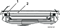
Install a spring washer and a screw on each end of the handle, but do not tighten the screws.
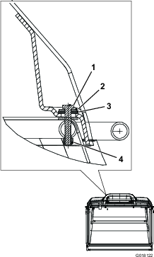
Starting from the front and moving rearward, secure the collector cover to the frame at 6 locations using a screw, 1 steel washer, 2 rubber washers, and a nut at each location (Figure 3).
Tighten the handle screws that you loosely installed in step 3.
Assemble the outer frame to the collector frame by inserting a hinge pin (from loose parts) through the holes on each side from inside the collector (Figure 4).
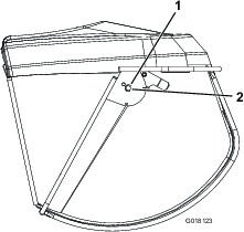
Secure a hinge pin on each side of the collector (on the outside of the collector), with a snap ring installed into the groove on the pin (Figure 4).
Slide the handle arm assembly into position, and secure at the bottom of the grass collector dump lever with a screw.
Note: You may need to adjust the switch activation plate so that the switch operates properly.
It may be necessary to add oil to the machine before first operation. Refer to the Operator’s Manual for oil type, viscosity, and crankcase capacity. Add only enough oil to raise the level to the Full mark on the dipstick.
Close sectionRemove the battery from the machine; refer to the Operator’s Manual.
Remove the filler caps from the top of the battery.
Battery electrolyte contains sulfuric acid, which is fatal if consumed and can severely burn you.
Do not drink electrolyte.
Avoid contact with skin, eyes, or clothing.
Wear safety glasses to shield your eyes and rubber gloves to protect your hands.
Fill the battery where clean water is available for flushing the skin.
Follow all instructions and comply with all safety messages on the electrolyte container.
Slowly pour electrolyte into each cell until the level is up to the lower part of the tube.
Leave the filler caps off, and connect a 3 to 4 A battery charger to the battery posts.
Charge the battery at a rate of 2 A or less for at least 24 hours (12 volts).
Important: Use only a battery charger set to 12 volts to charge the battery.
Important: Do not start the engine with a battery booster (jump starter) pack. Jump-starting the engine with a battery booster pack may damage electronic components of the machine.
Charging the battery produces gasses that can explode.
Never smoke near the battery, and keep sparks and flames away from the battery.
Install the filler caps after the battery is fully charged.
Install the battery in the chassis; refer to the Operator’s Manual.
Add fuel to the fuel tank; refer to the Operator’s Manual.
Close sectionCheck front and rear tires for proper inflation; refer to the Operator’s Manual for the recommended inflation pressure.
Close sectionEnsure that all of the necessary points on the machine are lubricated; refer to the Operator’s Manual.
Close sectionRefer to the Operator’s Manual.