


Maintenance
Note: Determine the left and right sides of the machine from the normal operating position.
Recommended Maintenance Schedule(s)
| Maintenance Service Interval | Maintenance Procedure |
|---|---|
| After the first 5 hours |
|
| Before each use or daily |
|
| After each use |
|
| Every 25 hours |
|
| Every 100 hours |
|
| Every 200 hours |
|
| Before storage |
|
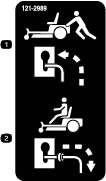
Caution
If you leave the key in the ignition switch, someone could accidently start the engine and seriously injure you or other bystanders.
Remove the key from the ignition and disconnect the wire from the spark plug before you do any maintenance. Set the wire aside so that it does not accidentally contact the spark plug.
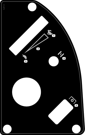
Pre-Maintenance Procedures
Raising the Seat
Ensure the parking brake is engaged and lift the seat forward.
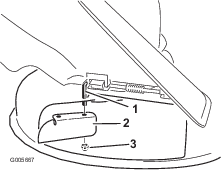
The following components can be accessed by raising the seat:
-
Serial plate
-
Service decal
-
Seat-adjustment bolts
-
Fuel filter
-
Battery and battery cables
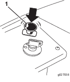
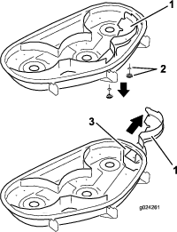
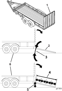
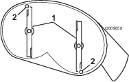
Releasing the Mower-Deck Curtain
Loosen the 2 bottom bolts of the curtain to gain access to the top of the mower deck (Figure 29).
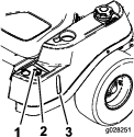
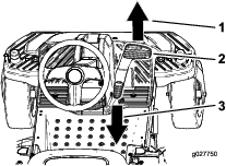
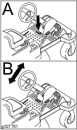
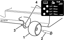
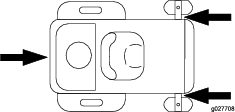
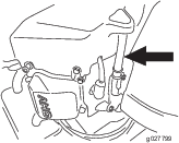
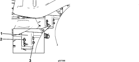
Raising the Front of the Machine
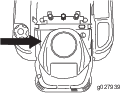
If the front of the machine needs to be raised, use the very front edge as show in Figure 30.
Important: To prevent damage to the steering mechanism, ensure the very front edge of the machine is used for jacking points.
Lubrication
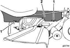
Greasing the Bearings
| Maintenance Service Interval | Maintenance Procedure |
|---|---|
| Every 25 hours |
|
Grease Type: No. 2 general purpose, lithium-base grease
-
Park the machine on a level surface, and disengage the blade-control switch.
-
Ensure the parking brake is engaged, stop the engine, remove the key, and wait for all moving parts to stop before leaving the operating position.
-
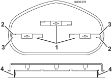
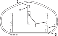
Clean the grease fittings (Figure 31 and Figure 32) with a rag.
Note: Make sure to scrape any paint off of the front of the fitting(s).
-
Connect a grease gun to each fitting (Figure 31 and Figure 32).
-
Pump grease into the fittings until grease begins to ooze out of the bearings.
Engine Maintenance
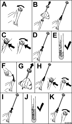
Servicing the Air Cleaner
Note: Service the air cleaner more frequently (every few hours) if operating conditions are extremely dusty or sandy.
Removing the Elements
-
Park the machine on a level surface and disengage the blade-control switch (PTO).
-
Engage the parking brake, stop the engine, remove the key, and wait for all moving parts to stop before leaving the operating position.
-
Clean around the air-cleaner cover to prevent dirt from getting into the engine and causing damage.
-
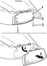
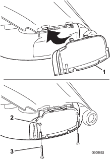
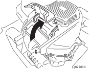
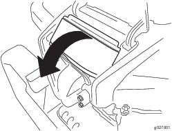
Lift the cover and rotate the air-cleaner assembly out of the engine (Figure 33).
-
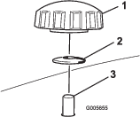
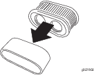
Remove the foam element from the paper element (Figure 34).
Servicing the Foam Element
| Maintenance Service Interval | Maintenance Procedure |
|---|---|
| Every 25 hours |
|
| Every 100 hours |
|
Wash the foam element with water and replace the foam element if it is damaged.
Servicing the Paper Element
| Maintenance Service Interval | Maintenance Procedure |
|---|---|
| Every 100 hours |
|
| Every 200 hours |
|
-
Lightly tap the element on a flat surface to remove dust and dirt.
-
Inspect the element for tears, an oily film, and damage to the seal.
Important: Do not clean the paper element with pressurized air or liquids, such as solvent, gas, or kerosene. Replace the paper element if it is damaged or cannot be cleaned thoroughly.
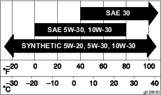
Servicing the Engine Oil
Oil Type: Detergent oil (API service SF, SG, SH, SJ, or SL)
Crankcase Capacity: 2.4 L (2.5 US qt)
Viscosity: See the table below.
Checking the Engine-Oil Level
| Maintenance Service Interval | Maintenance Procedure |
|---|---|
| Before each use or daily |
|
Note: Check the oil when the engine is cold.
Warning
Contact with hot surfaces may cause personal injury.
Keep hands, feet, face, clothing, and other body parts away the muffler and other hot surfaces.
Important: Do not overfill the crankcase with oil, because damage to the engine may result. Do not run engine with oil below the Low mark, because the engine may be damaged.
-
Park the machine on a level surface, disengage the blade-control switch, stop the engine, engage parking brake, and remove the key.
-
Make sure the engine is stopped, level, and is cool, so the oil has had time to drain into the sump.
-
To keep dirt, grass clippings, etc., out of the engine, clean the area around the oil-fill cap and dipstick before removing it (Figure 36).
-
Stop the engine, remove the key, and wait for all moving parts to stop before leaving the operating position.
Changing the Engine Oil and Oil Filter
| Maintenance Service Interval | Maintenance Procedure |
|---|---|
| After the first 5 hours |
|
| Every 100 hours |
|
Note: Change the engine-oil filter more frequently when operating conditions are extremely dusty or sandy.
Note: Dispose of the used oil at a recycling center.
-
Park the machine on a level surface to ensure the oil drains completely.
-
Disengage the PTO and ensure the parking brake is engaged.
-
Stop the engine, remove the key, and wait for all moving parts to stop before leaving the operating position.
-
Drain the engine oil.
-
Change the engine oil filter (Figure 38).
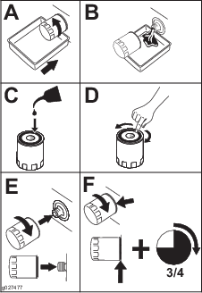
Note: Ensure that the oil-filter gasket touches the engine and then turn the filter an extra 3/4 turn.
-
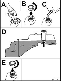
Slowly pour approximately 80% of the specified oil into the filler tube and slowly add the additional oil to bring it to the Full mark (Figure 39).
Servicing the Spark Plug
| Maintenance Service Interval | Maintenance Procedure |
|---|---|
| Every 100 hours |
|
| Every 200 hours |
|
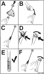
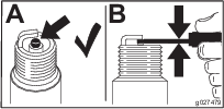
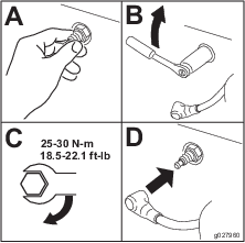
Make sure the air gap between the center and side electrodes is correct before installing the spark plug. Use a spark-plug wrench for removing and installing the spark plug(s) and a gapping tool/feeler gauge to check and adjust the air gap. Install a new spark plug(s) if necessary.
Type: Champion® RN9YC or NGK® BPR6ES
Air gap: 0.76 mm (0.03 inch)
Removing the Spark Plug
-
Disengage the PTO and ensure the parking brake is engaged.
-
Stop the engine, remove the key, and wait for all moving parts to stop before leaving the operating position.
Note: Due to the deep recess around the spark plug, blowing out the cavity with compressed air is usually the most effective method for cleaning. The spark plug is most accessible when the blower housing is removed for cleaning.
Checking the Spark Plug
Important: Do not clean the spark plug(s). Always replace the spark plug(s) when it has: a black coating, worn electrodes, an oily film, or cracks.
If you see light brown or gray on the insulator, the engine is operating properly. A black coating on the insulator usually means the air cleaner is dirty.
Set the gap to 0.76 mm (0.030 inch).
Installing the Spark Plug
Tighten the spark plug(s) to 25–30 N-m (18.5–22.1 ft-lb).
Cleaning the Cooling System
| Maintenance Service Interval | Maintenance Procedure |
|---|---|
| Before each use or daily |
|
Clean the air intake screen from grass and debris before each use.
-
Disengage the blade control switch and apply the parking brake.
-
Stop the engine, remove the key, and wait for all moving parts to stop before leaving the operating position.
-
Remove the air filter from the engine.
-
Remove the engine shroud.
-
To prevent debris entering the air intake, install the air filter to the filter base.
-
Clean debris and grass from the parts.
-
Remove the air filter and install the engine shroud.
-
Install the air filter.
Fuel System Maintenance
Danger
In certain conditions, gasoline is extremely flammable and highly explosive. A fire or explosion from gasoline can burn you, others, and can damage property.
-
Perform any fuel-related maintenance when the engine is cold. Do this outdoors in an open area. Wipe up any gasoline that spills.
-
Never smoke when draining gasoline, and stay away from an open flame or where a spark may ignite the gasoline fumes.
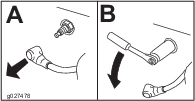
Replacing the In-Line Fuel Filter
| Maintenance Service Interval | Maintenance Procedure |
|---|---|
| Every 100 hours |
|
| Every 200 hours |
|
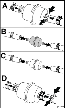
Never install a dirty filter if it is removed from the fuel line.
-
Park the machine on a level surface and disengage the blade-control switch.
-
Ensure the brake is engaged, stop the engine, remove the key, and wait for all moving parts to stop before leaving the operating position.
Electrical System Maintenance
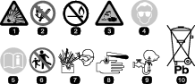
Warning
Battery posts, terminals, and related accessories contain lead and lead compounds, chemicals known to the State of California to cause cancer and reproductive harm. Wash hands after handling.
Charging the Battery
Removing the Battery
Warning
Battery terminals or metal tools could short against metal machine components causing sparks. Sparks can cause the battery gasses to explode, resulting in personal injury.
-
When removing or installing the battery, do not allow the battery terminals to touch any metal parts of the machine.
-
Do not allow metal tools to short between the battery terminals and metal parts of the machine.
-
Park the machine on a level surface and disengage the blade control switch.
-
Ensure the parking brake is engaged, stop the engine, remove the key, and wait for all moving parts to stop before leaving the operating position.
-
Raise the seat to access the battery.
-
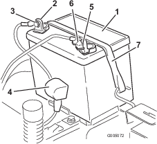
Disconnect the negative (black) ground cable from the battery post (Figure 44). Retain all fasteners.
Warning
Incorrect battery cable routing could damage the machine and cables causing sparks. Sparks can cause the battery gasses to explode, resulting in personal injury.
-
Always disconnect the negative (black) battery cable before disconnecting the positive (red) cable.
-
Always connect the positive (red) battery cable before connecting the negative (black) cable.
-
-
Slide the rubber cover up the positive (red) cable. Disconnect the positive (red) cable from the battery post (Figure 44). Retain all fasteners.
-
Remove the battery hold-down (Figure 44) and lift the battery from the battery tray.
Charging the Battery
| Maintenance Service Interval | Maintenance Procedure |
|---|---|
| Before storage |
|
-
Remove the battery from the chassis; refer to Removing the Battery.
-
Charge the battery for a minimum of 1 hour at 6 to 10 amps. Do not overcharge the battery.
-
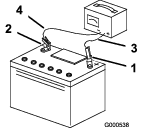
When the battery is fully charged, unplug the charger from the electrical outlet, then disconnect the charger leads from the battery posts (Figure 45).
Installing the Battery
-
Position the battery in the tray (Figure 44).
-
Install the positive (red) battery cable to the positive (+) battery terminal using the fasteners removed previously.
-
Install the negative battery cable to the negative (-) battery terminal using the fasteners removed previously.
-
Slide the red terminal boot onto the positive (red) battery post.
-
Secure the battery with the hold-down (Figure 44).
-
Lower the seat.
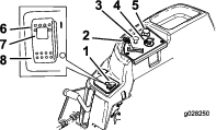
Servicing the Fuses
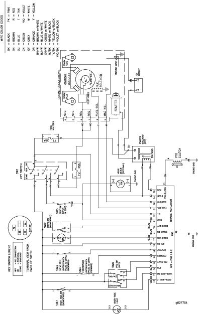
The electrical system is protected by fuses. It requires no maintenance; however, if a fuse blows, check the component/circuit for a malfunction or short.
Fuse type:
-
Main—F1-30 amp, blade-type
-
Charge Circuit—F2-25 amp, blade-type
-
Remove the screws securing the control panel to the machine.
Note: Retain all fasteners.
-
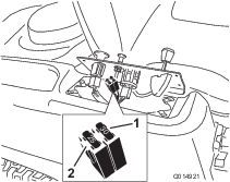
Lift the control pane up to access the main wiring harness and fuse block (Figure 46).
-
To replace a fuse, pull out on the fuse to remove it (Figure 46).
-
Return the control panel to its original position.
Note: Use the screws removed previously to secure the panel to the machine.
Drive System Maintenance
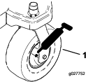
Checking the Tire Pressure
| Maintenance Service Interval | Maintenance Procedure |
|---|---|
| Every 25 hours |
|
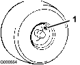
Maintain the air pressure in the front and rear tires as specified. Uneven tire pressure can cause uneven cut. Check the pressure at the valve stem (Figure 47). Check the tires when they are cold to get the most accurate pressure reading.
Refer to the maximum pressure suggested by the tire manufacturer on the sidewall of the caster wheel tires.
Inflate the rear drive wheel tires to 90 kPa (13 psi).
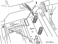
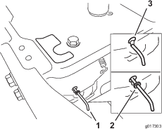
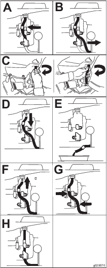
Releasing the Electric Brake
The electric brake can be release by manually rotating the link arms forward. Once the electric brake is energized the brake will reset.
To release the brake:
-
Turn the ignition key to the Off position or disconnect the battery.
-
Locate the shaft on the electric brake where the brake link arms are connected.
-
Rotate the shaft forward to release the brake.
Mower Maintenance
Servicing the Cutting Blades
Maintain sharp blades throughout the cutting season, because sharp blades cut cleanly without tearing or shredding the grass blades. Tearing and shredding turns grass brown at the edges, which slows growth, and increases the chance of disease.
Check the cutter blades daily for sharpness, and for any wear or damage. File down any nicks and sharpen the blades as necessary. If a blade is damaged or worn, replace it immediately with a genuine Toro replacement blade. For convenient sharpening and replacement, you may want to keep extra blades on hand.
Warning
A worn or damaged blade can break, and a piece of the blade could be thrown into the operator's or bystander's area, resulting in serious personal injury or death.
-
Inspect the blade periodically for wear or damage.
-
Replace a worn or damaged blade.
Before Inspecting or Servicing the Blades
Park the machine on a level surface, disengage the blade-control switch, ensure the parking brake is engaged, stop the engine, and remove the key.
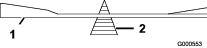
Inspecting the Blades
| Maintenance Service Interval | Maintenance Procedure |
|---|---|
| Before each use or daily |
|
-
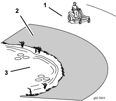
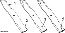
Inspect the cutting edges (Figure 49).
Note: If the edges are not sharp or have nicks, remove and sharpen the blades; refer to Sharpening the Blades.
-
Inspect the blades, especially the curved area (Figure 49).
Note: If you notice any damage, wear, or a slot forming in this area (item 3 in Figure 49), immediately install a new blade.
Checking for Bent Blades
Note: The machine must be on a level surface for the following procedure.
-
Raise the mower deck to the highest height-of-cut position; also considered the 'transport' position.
-
While wearing thickly padded gloves, or other adequate hand protection, slowly rotate the blade to be measure into a position that allows effective measurement of the distance between the cutting edge and the level surface the machine is on (Figure 50).
-
Measure from the tip of the blade to the flat surface (Figure 51).
-
Rotate the same blade 180 degrees, so that the opposing cutting edge is now in the same position (Figure 52).
-
Measure from the tip of the blade to the flat surface (Figure 53).
Note: The variance should be no more than 3 mm (1/8 inch).
-
If the difference is greater than 3 mm (1/8 inch), replace the blade with a new blade; refer toRemoving the Blades and Installing the Blades.
Note: If a bent blade is replaced with a new one, and the dimension obtained continues to exceed 3mm (1/8 inch), the blade spindle could be bent. Contact an Authorized Toro Dealer for service.
-
If the variance is within constraints, move to the next blade.
-
Repeat this procedure on each blade.
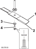
Removing the Blades
The blades must be replaced if a solid object is hit, if the blade is out of balance, or if the blade is bent. To ensure optimum performance and continued safety conformance of the machine, use genuine Toro replacement blades. Replacement blades made by other manufacturers may result in non-conformance with safety standards.
-
Hold the blade end using a rag or thickly-padded glove.
-
Remove the blade bolt, the curved washer, and the blade from the spindle shaft (Figure 54).
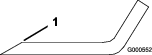
Sharpening the Blades
-
Use a file to sharpen the cutting edge at both ends of the blade (Figure 55).
Note: Maintain the original angle.
Note: The blade retains its balance if the same amount of material is removed from both cutting edges.
-
Check the balance of the blade by putting it on a blade balancer (Figure 56).
Note: If the blade stays in a horizontal position, the blade is balanced, and can be used.
Note: If the blade is not balanced, file some metal off the end of the sail area only (Figure 55).
-
Repeat this procedure until the blade is balanced.
Installing the Blades
-
Install the blade onto the spindle shaft (Figure 54).
Important: The curved part of the blade must be pointing upward toward the inside of the mower to ensure proper cutting.
-
Install the curved washer (cupped side toward the blade) and the blade bolt (Figure 54).
-
Torque the blade bolt to 47 to 88 N-m (35 to 65 ft-lb).
Leveling the Mower Deck
Check to ensure that the mower deck is level any time you install the mower or when you see an uneven cut on your lawn.
The mower deck must be checked for bent blades prior to leveling; any bent blades must be removed and replaced; refer to the Checking for Bent Blades before continuing.
The mower deck must be leveled side-to-side first then the front to rear slope can be adjusted.
Requirements:
-
The machine must be on a level surface.
-
All tires must be properly inflated; refer to Checking the Tire Pressure.
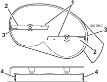
Side-to-Side Leveling
-
Park the machine on a level surface and disengage the blade-control switch.
-
Ensure the parking brake is engaged, stop the engine, remove the key, and wait for all moving parts to stop before leaving the operating position.
-
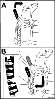
Set the height-of-cut lever to middle position.
-
Carefully rotate the blades so that they are all side to side (Figure 57 and Figure 58).
-
Measure between the outside cutting edges and the flat surface (Figure 57 and Figure 58).
Note: If both measurements are not within 5 mm (3/16 inch), an adjustment is required; continue with this procedure.
-
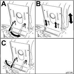
Move to the left side of the machine.
-
Loosen the side locking nut.
-
Raise or lower the left side of the mower deck by rotating the rear nut (Figure 59).
Note: Rotate the rear nut clockwise to raise the mower deck; rotate the rear nut counter-clockwise to lower the mower deck. (Figure 59).
-
Check the side-to-side adjustments again. Repeat this procedure until the measurements are correct.
-
Continue leveling the mower deck by checking the front-to-rear blade slope; refer to Adjusting the Front-to-Rear Blade Slope.
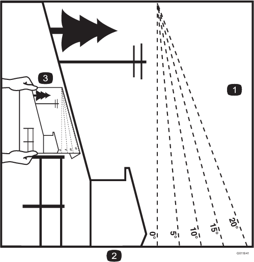
Adjusting the Front-to-Rear Blade Slope
Check the front-to-rear blade level any time you install the mower. If the front of the mower is more than 7.9 mm (5/16 inch) lower than the rear of the mower, adjust the blade level using the following instructions:
-
Park the machine on a level surface and disengage the blade-control switch.
-
Ensure the parking brake is engaged., stop the engine, remove the key, and wait for all moving parts to stop before leaving the operating position.
-
Set the height-of-cut lever to middle position.
Note: Check and adjust the side-to-side blade level if you have not checked the setting; refer to Side-to-Side Leveling.
-
Carefully rotate the blades so they are facing front to rear (Figure 60 and Figure 61).
-
Measure from the tip of the front blade to the flat surface, and the tip of the rear blade to the flat surface (Figure 60 and Figure 61).
Note: If the front blade tip is not 1.6 to 7.9 mm (1/16 to 5/16 inch) lower than the rear blade tip, adjust the front locknut.
-
To adjust the front-to-rear blade slope, rotate the adjustment nut in the front of the mower (Figure 62).
-
To raise the front of the mower, tighten the adjustment nut.
-
To lower the front of the mower, loosen the adjustment nut.
-
After adjustment, check the front-to-rear slope again, continue adjusting the nut until the front blade tip is 1.6 to 7.9 mm (1/16 to 5/16 inch) lower than the rear blade tip (Figure 60 and Figure 61).
-
When the front-to-rear blade slope is correct check the side-to-side level of the mower again, refer to Side-to-Side Leveling.
Removing the Mower
-
Park the machine on a level surface and disengage the blade-control switch.
-
Ensure the parking brake is engaged, stop the engine, remove the key, and wait for all moving parts to stop before leaving the operating position.
-
Lower the height-of-cut lever to the lowest position.
-
Loosen the bottom two bolts holding the mower-deck curtain to the mower deck. Refer to Releasing the Mower-Deck Curtain.
-
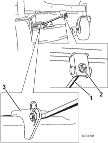
Remove the hairpin-cotter pin from the front support rod, and remove the rod from the deck bracket (Figure 63).
-
Carefully lower the front of the mower deck to the ground.
-
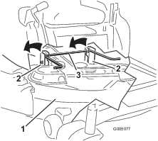
Lift the mower deck and hanger brackets clear of the rear lift rod and lower the mower carefully to the ground (Figure 64).
-
Slide the mower deck rearward to remove the mower belt from the engine pulley.
-
Slide the mower deck out from underneath the machine.
Note: Retain all parts for future installation.
Installing the Mower
-
Park the machine on a level surface and disengage the blade-control switch.
-
Ensure the parking brake is engaged, stop the engine, remove the key, and wait for all moving parts to stop before leaving the operating position.
-
Slide the mower under the machine.
-
Lower the height-of-cut lever to the lowest position.
-
Lift the rear of the mower deck and guide the hanger brackets over the rear lift rod (Figure 64).
-
Attach the front support rod to the mower deck with the clevis pin and hairpin-cotter pin (Figure 63).
-
Install the mower belt onto the engine pulley; refer to Replacing the Mower Belt.
-
Tighten the bottom 2 bolts for the mower-deck curtain to the mower deck. Refer to Releasing the Mower-Deck Curtain.
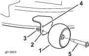
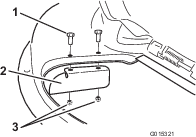
Replacing the Grass Deflector
| Maintenance Service Interval | Maintenance Procedure |
|---|---|
| Before each use or daily |
|
Warning
An uncovered discharge opening could allow the lawn mower to throw objects in the operator's or bystander's direction and result in serious injury. Also, contact with the blade could occur.
Never operate the machine without the grass deflector, the discharge cover, or the grass-collection system in place.
Inspect the grass deflector for damage before each use. Replace any damaged parts before use.
-
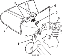
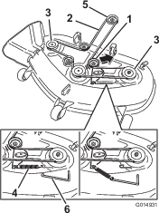
Remove the nut (3/8 inch) from the rod under the mower (Figure 65).
-
Slide the rod out of the short standoff, the spring, and the grass deflector (Figure 65).
-
Remove the damaged or worn grass deflector.
-
Replace the grass deflector (Figure 65).
-
Slide the rod (straight end), through the rear-grass-deflector bracket.
-
Place the spring on the rod, with the end wires down and between the grass deflector brackets.
-
Slide rod through the second grass-deflector bracket (Figure 65).
-
Insert the rod at the front of the grass deflector into the short standoff on the deck.
-
Secure the rear end of the rod into the mower with a nut (3/8 inch) as shown in Figure 65.
Important: The grass deflector must be spring loaded and in the down position. Lift the deflector up to test that it snaps to the full down position.
Mower Belt Maintenance
Inspecting the Belts
| Maintenance Service Interval | Maintenance Procedure |
|---|---|
| Every 25 hours |
|
Check the belts for cracks, frayed edges, burn marks, or any other damage. Replace damaged belts.
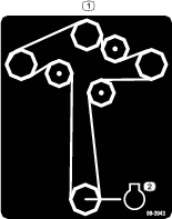
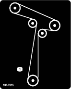
Replacing the Mower Belt
Squealing when the belt is rotating, blades slipping when cutting grass, frayed belt edges, burn marks, and cracks are signs of a worn mower belt. Replace the mower belt if any of these conditions are evident.
-
Park the machine on a level surface and disengage the blade-control switch.
-
Ensure the parking brake is engaged, stop the engine, remove the key, and wait for all moving parts to stop before leaving the operating position.
-
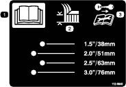
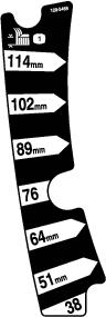
Set the height-of-cut at the lowest cutting position of 38 mm (1-1/2 inches).
-
Loosen the bottom two bolts holding the mower-deck curtain to the mower deck. Refer to Releasing the Mower-Deck Curtain.
-
Using a spring-removal tool, (Toro part no. 92-5771), remove the idler spring from the deck hook to remove tension on the idler pulley, and roll the belt off of the pulleys (Figure 66 and Figure 67).
Warning
The spring is under tension when installed and can cause personal injury.
Be careful when removing the belt.
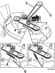
-
Route the new belt around the engine pulley and mower pulleys (Figure 67).
-
Using a spring-removal tool, install the idler spring over the deck hook, and place tension on the idler pulley and mower belt (Figure 66 and Figure 67).
-
Tighten the bottom 2 bolts for the mower-deck curtain to the mower deck. Refer to Releasing the Mower-Deck Curtain.
Cleaning
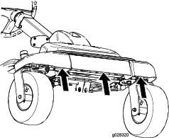
Cleaning Under the Front of the Machine
| Maintenance Service Interval | Maintenance Procedure |
|---|---|
| After each use |
|
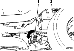
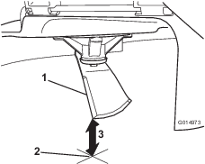
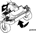
Remove debris under the front of the machine with compressed air or by hand with a brush (Figure 68).
Note: Do not use water to clean under the front of the machine, this can cause build up of debris.
Washing the Underside of the Mower
| Maintenance Service Interval | Maintenance Procedure |
|---|---|
| After each use |
|
Important: You can wash the machine with a mild detergent and water. Do not pressure wash the machine. Avoid excessive use of water, especially near the control panel, under the seat, around the engine, hydraulic pumps, and motors.
Wash the underside of the mower after each use to prevent grass buildup for improved mulch action and clipping dispersal.
-
Park the machine on a level surface and disengage the blade-control switch.
-
Ensure the parking brake is engaged, stop the engine, remove the key, and wait for all moving parts to stop before leaving the operating position.
-
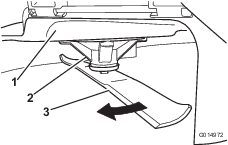
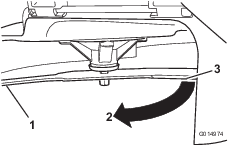
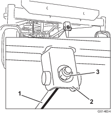
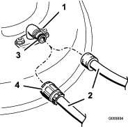
Attach the hose coupling to the end of the mower washout fitting, and turn the water on high (Figure 69).
Note: Spread petroleum jelly on the washout fitting O-ring to make the coupling slide on easier and protect the O-ring.
-
Lower the mower to the lowest height-of-cut.
-
Sit on the seat and start the engine.
-
Engage the blade-control switch and let the mower run for 1 to 3 minutes.
-
Disengage the blade-control switch, stop the engine, remove the ignition key, and wait for all moving parts to stop.
-
Turn the water off and remove the coupling from the washout fitting.
Note: If the mower is not clean after one washing, soak it and let it stand for 30 minutes. Then, repeat the process.
-
Run the mower again for 1 to 3 minutes to remove excess water.
Warning
A broken or missing washout fitting could expose you and others to thrown objects or blade contact. Contact with blade or thrown debris can cause injury or death.
-
Replace broken or missing washout fitting immediately, before using mower again.
-
Never put your hands or feet under the mower or through openings in the mower.
-