


Maintenance
Note: Determine the left and right sides of the machine from the normal operating position.
Recommended Maintenance Schedule(s)
| Maintenance Service Interval | Maintenance Procedure |
|---|---|
| After the first 5 operating hours |
|
| Before each use or daily |
|
| Every 25 hours |
|
| Every 50 hours |
|
| Every 100 hours |
|
| Yearly or before storage |
|
Important: Refer to your engine operator’s manual for additional maintenance procedures.
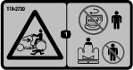
Caution
If you leave the key in the ignition switch, someone could accidently start the engine and seriously injure you or other bystanders.
Remove the key from the ignition and disconnect the wire from the spark plug before you do any maintenance. Set the wire aside so that it does not accidentally contact the spark plug.
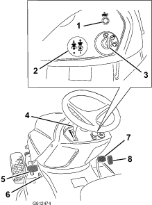
Lubrication
Greasing and Lubricating the Machine
Grease the machine with a general-purpose grease.
-
Disengage the blades (PTO).
-
Set the parking brake.
-
Stop the engine and wait for all moving parts to stop.
-
Remove the ignition key.
-
Clean the grease fittings with a rag. Scrape any paint off the front of the fittings.
-
Connect a grease gun to each fitting and pump grease into it.
-
Wipe up any excess grease.
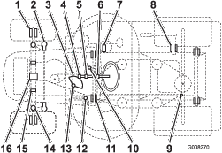
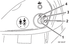
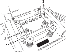
| Item | Name | Quantity (pumps) | Interval (hours) | Lubricant |
| 1 | Front wheel—grease fittings | 2 | 25 | Grease |
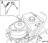
| 2 | Steering ball joints | 4 | 50 | Oil |
| 3 | Steering sector gear | 1 | 50 | Grease |
| 4 | Steering pinion gear | 1 | 25 | Grease |
| 5 | Steering shaft bearing | 1 | 50 | Oil |
| 6 | Steering shaft bearing | 1 | 50 | Oil |
| 7 | Motion lever | 1 | 50 | Grease |
| 8 | Shaft hub for lifting the mower housing | 1 | 50 | Oil |
| 9 | Motion link ball joints | 4 | 50 | Oil |
| 10 | Traction idler pulley belt—grease fitting | 1 | 50 | Grease |
| 11 | Brake pedal shaft pivot points | 2 | 50 | Oil |
| 12 | Parking brake ring | 1 | 50 | Oil |
| 13 | Steering bearing | 1 | 25 | Grease |
| 14 | Left and Right Spindle—grease fittings | 2 | 25 | Grease |
| 15 | Mower housing hinged pins | 6 | When removed | Grease |
| 16 | Front axle pivot pins | 2 | When removed | Grease |
Engine Maintenance
Servicing the Air Cleaner
-
Park the machine on a level surface.
-
Disengage the blades (PTO).
-
Set the parking brake.
-
Stop the engine and wait for all moving parts to stop.
-
Remove the ignition key.
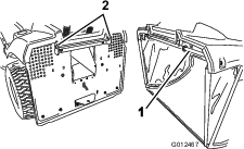
Removing the Air Filter
-
Clean around the air filter cover to prevent dirt from getting into the engine and causing damage.
-
Turn the knobs to the Unlock position (Figure 21).
-
Remove the air filter cover.
-
To remove the filter, lift the end of the filter (Figure 21).
Cleaning the Air Filter
-
Inspect the air filter for tears, an oily film, or damage to the rubber seal.
-
To loosen debris, gently tap the filter on a hard surface. If the filter is excessively dirty, replace it with a new filter.
Important: Never clean the air filter with pressurized air or liquids, such as solvents, gasoline, or kerosene. Replace the air filter if it is damaged or cannot be cleaned thoroughly.
Close sectionInstalling the Air Filter
-
Install the air filter into the engine base and push down until the filter snaps in place.
-
Install the air filter cover and knobs (Figure 21).
-
Close the hood.
Servicing the Engine Oil
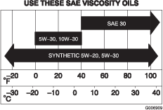
Oil Type: Detergent oil (API classification SJ or higher)
Crankcase capacity: 1.4 L (48 oz) with filter; 1.3 L (44 oz) without filter
Viscosity: See the oil table (Figure 22).
Checking the Engine Oil Level
-
Park the machine on a level surface.
-
Disengage the blades (PTO).
-
Set the parking brake.
-
Stop the engine and wait for all moving parts to stop.
-
Remove the ignition key.
-
Allow the engine to cool.
-
Open the hood.
-
Clean around the dipstick (Figure 23) so that dirt cannot fall into the filler hole and damage the engine.
-
Unscrew the dipstick and wipe the metal end clean (Figure 23).
-
Screw the dipstick fully onto the filler tube (Figure 23).
-
Unscrew the dipstick again and look at the metal end. If the engine oil level is low, slowly pour only enough oil into the filler tube to raise the level to the Full mark on the dipstick.
Important: Do not overfill the crankcase with engine oil and run the engine; engine damage may result.
Changing the Engine Oil
-
Start the engine and let it run for 5 minutes.
Note: This warms the oil so that it drains better.
-
Park the machine so that the drain side is slightly lower than the other side to ensure that the oil drains completely.
-
Disengage the blades (PTO).
-
Set the parking brake.
-
Stop the engine and wait for all moving parts to stop.
-
Remove the ignition key.
-
Open the hood.
-
Place a pan below the drain plug.
-
Remove the drain plug to allow the oil to drain (Figure 24).
-
When the oil has drained completely, insert the drain plug and tighten it securely.
Note: Recycle the used engine oil properly.
-
Clean around the dipstick and unscrew the cap (Figure 23).
-
Slowly pour approximately 80% of the engine oil into the filler tube (Figure 23).
-
Check the engine oil level; refer to steps 10 and 11 of Checking the Engine Oil Level.
Changing the Engine Oil Filter
-
Drain the oil from the engine; refer to Changing the Engine Oil.
-
Remove the old filter and wipe off the adapter gasket surface (Figure 25).
-
Apply a thin coat of new engine oil to the rubber gasket on the new filter (Figure 25).
-
Install the new filter to the filter adapter by turning it clockwise until the gasket contacts the filter adapter.
-
Tighten the filter an additional 1/2 to 3/4 turn (Figure 25).
-
Fill the crankcase with the proper type of new engine oil; refer to Checking the Engine Oil Level.
Servicing the Spark Plug
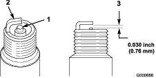
Use a Champion RC12YC or equivalent spark plug. Ensure that the air gap between the center and side electrodes is 0.76 mm before installing the spark plug. Use a spark plug wrench for removing and installing the spark plug and a gapping tool or feeler gauge to check and adjust the air gap.
Removing the Spark Plug
-
Disengage the blades (PTO).
-
Set the parking brake.
-
Stop the engine and wait for all moving parts to stop.
-
Remove the ignition key.
-
Open the hood.
-
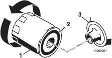
Disconnect the wire from the spark plug (Figure 26).
-
Clean around the spark plug to prevent dirt from falling into the engine and potentially causing damage.
-
Remove the spark plug and the metal washer (Figure 26).
Checking the Spark Plug
-
Look at the center of the spark plug (Figure 27). If you see light brown or gray on the insulator, the engine is operating properly. A black coating on the insulator usually means that the air cleaner is dirty.
Important: Do not clean the spark plug. Always replace the spark plug when it has a black coating, worn electrodes, an oily film, or cracks.
-
Check the gap between the center and side electrodes (Figure 27) and bend the side electrode if the gap is not correct.
Installing the Spark Plug
-
Install the spark plug and metal washer. Ensure that the air gap is set correctly.
-
Tighten the spark plug to 20.4 N-m.
-
Connect the wire to the spark plug (Figure 26).
-
Close the hood.
Fuel System Maintenance
Draining the Fuel Tank
Drain the fuel tank when you will not be using the machine for more than 30 days.
Danger
In certain conditions, fuel and fuel vapors are extremely flammable and highly explosive. A fire or explosion from fuel can burn you and others and can damage property.
-
Drain fuel from the fuel tank when the engine is cold. Do this outdoors in an open area. Wipe up any fuel that spills.
-
Never smoke when draining fuel, and stay away from an open flame or where a spark may ignite the fuel fumes.
-
Park the machine so that the left front side is slightly lower than the right side to ensure that the fuel tank drains completely.
-
Disengage the blades (PTO).
-
Set the parking brake.
-
Stop the engine and wait for all moving parts to stop.
-
Remove the ignition key.
-
Close the fuel shut-off valve located under the front of the fuel tank.
-
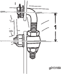
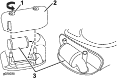
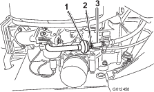
Loosen the hose clamp at the fuel filter and slide it up the fuel line away from the fuel filter (Figure 28).
-
Pull the fuel line off the fuel filter (Figure 28).
-
Open the fuel shut-off valve and allow the fuel to drain into an approved fuel container or a drain pan.
Note: Now is the best time to install a new fuel filter because the fuel tank is empty.
-
Install the fuel line onto the fuel filter.
-
Slide the hose clamp close to the fuel filter to secure the fuel line (Figure 28).
Replacing the Fuel Filter
The best time to replace the fuel filter (Figure 28) is when the fuel tank is empty. Never install a dirty fuel filter after it has been removed from the fuel line.
-
Park the machine on a level surface.
-
Disengage the blades (PTO).
-
Set the parking brake.
-
Stop the engine and wait for all moving parts to stop.
-
Remove the ignition key.
-
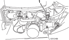
Close the fuel-shutoff valve (Figure 29).
-
Squeeze the ends of the hose clamps together and slide them away from the old fuel filter (Figure 29).
-
Remove the old fuel filter from the fuel line.
-
Install a new fuel filter and move the hose clamps close to it.
-
Open the fuel-shutoff valve.
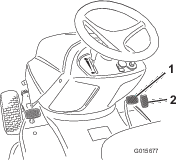
Electrical System Maintenance
Replacing the Fuses
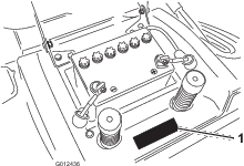
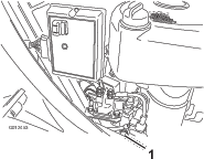
The electrical system is protected by fuses. They are located beneath the hood, near the fuel tank (Figure 30). If a fuse goes out, check the circuit wiring for a short.
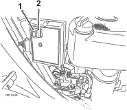
To replace a fuse, pull up to remove the old fuse from the socket. Insert a new fuse by pushing it down into the socket.
Note: Ensure that the new fuse has the same amperage as the old fuse that you are replacing.
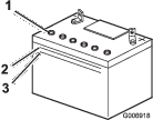
Close sectionServicing the Battery
Important: Do not start the engine with a battery booster (jump starter) pack. Jump-starting the engine with a battery booster pack may damage electronic components of the machine.
Always keep the battery clean and fully charged. Use a paper towel to clean the battery and battery box. If the battery terminals are corroded, clean them with a solution of 4 parts water and 1 part baking soda. Apply a light coating of grease to the battery terminals to prevent them from corroding.
Battery voltage and amperage: 12 volts, 190 cold cranking amps
Removing the Battery
Warning
Battery terminals or metal tools could short against metal machine components causing sparks. Sparks can cause the battery gasses to explode, resulting in personal injury.
-
When removing or installing the battery, do not allow the battery terminals to touch any metal parts of the machine.
-
Do not allow metal tools to short between the battery terminals and the metal parts of the machine.
-
Disengage the blades (PTO).
-
Set the parking brake.
-
Stop the engine and wait for all moving parts to stop.
-
Remove the ignition key.
-
Lift up the seat to see the battery.
-
Lift the rubber cover up off the negative (black) cable.
-
Disconnect the negative (black) ground cable from the battery post (Figure 31).
Warning
Routing the battery cables improperly could damage the machine and cables, causing sparks. Sparks can cause the battery gasses to explode, resulting in personal injury.
-
Always disconnect the negative (black) battery cable before disconnecting the positive (red) cable.
-
Always connect the positive (red) battery cable before connecting the negative (black) cable.
-
-
Lift the rubber cover up off the positive (red) cable.
-
Disconnect the positive (red) cable from the battery post (Figure 31).
-
Remove the battery hold down rod.
-
Remove the battery from the chassis.
Installing the Battery
-
Place the battery into the chassis with the battery posts toward the rear of the machine (Figure 31).
-
Secure the battery in the chassis with the hold down rod.
-
Using the bolt and wing nut, connect the positive (red) cable to the positive (+) battery post (Figure 31). Slide the rubber cover over the battery post.
-
Using the bolt and wing nut, connect the negative (black) cable to the negative (–) battery post (Figure 31). Slide the rubber cover over the battery post.
Checking the Electrolyte Level
-
Tip the seat forward to see the battery.
-
Look at the side of the battery. The electrolyte must be up to the upper line (Figure 32).
Note: Do not allow the electrolyte to fall below the lower line (Figure 32).
-
If the electrolyte is low, add the required amount of distilled water; refer to Adding Water to the Battery.
Danger
Battery electrolyte contains sulfuric acid which is a deadly poison and causes severe burns.
-
Do not drink electrolyte and avoid contact with skin, eyes or clothing. Wear safety glasses to shield your eyes and rubber gloves to protect your hands.
-
Fill the battery where clean water is always available for flushing the skin.
-
Adding Water to the Battery
The best time to add distilled water to the battery is just before you operate the machine. This lets the water mix thoroughly with the electrolyte solution.
-
Clean the top of the battery with a paper towel.
-
Remove the filler caps (Figure 32).
-
Slowly pour distilled water into each battery cell until the level is up to the lower part of the tube (Figure 32).
Important: Do not overfill the battery. Electrolyte (sulfuric acid) can severely corrode and damage the chassis.
-
Install the filler caps.
Charging the Battery
Warning
Charging the battery produces gasses that can explode. Never smoke near the battery and keep sparks and flames away from the battery.
Important: Always keep the battery fully charged (1.260 specific gravity), especially below 32°F (0°C) to prevent battery damage.
-
Remove the battery from the chassis; refer to Removing the Battery.
-
Check the electrolyte level; refer to Checking the Electrolyte Level.
-
Remove the filler caps from the battery and connect a 2 A battery charger to the battery posts.
-
Charge the battery at a rate of 2 A or less for 24 hours (12 volts).
Important: Use only a battery charger set to 12 volts to charge the battery.
-
When the battery is fully charged, install the filler caps.
-
Install the battery in the chassis; refer to Installing the Battery.
Drive System Maintenance
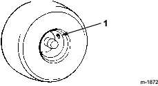
Checking the Tire Pressure
Maintain the air pressure in the front tires at 100 kPa (15 psi) and in the rear tires at 80 kPa (12 psi). Check the pressure at the valve stem (Figure 33). Check the tires when they are cold to get the most accurate pressure reading.
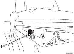
Servicing the Brake
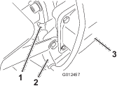
The brake is located on the right side of the rear axle, inside the rear tire (Figure 34).
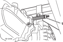
Note: If the machine takes more than 1 m (3 ft) to stop at high speed in the highest gear, adjust the brake.
Checking the Brake
-
Park the machine on a level surface.
-
Disengage the blades (PTO).
-
Set the parking brake.
-
Stop the engine and wait for all moving parts to stop.
-
Remove the ignition key.
-
Pull the drive control out to the Push position (Figure 13).
-
If the rear wheels lock and skid when you push the machine forward, you do not need to adjust the brake. If the wheels turn and do not lock, adjust the brake; refer to Adjusting the Brake.
Adjusting the Brake
-
Check the brake before you adjust it; refer to Checking the Brake.
-
Ensure that the drive control is in the Operate position (Figure 13) and that the parking brake is on.
-
Turn the brake adjusting nut clockwise until you cannot push the machine (Figure 34).
-
Release the parking brake and ensure that the rear wheels rotate freely when you push the machine. If they do not, turn the brake adjusting nut counterclockwise just enough so that you can push the machine.
-
Check the brake operation again; refer to Checking the Brake.
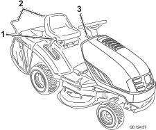
Removing the Grass Collector
-
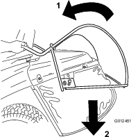
Lock the locking pin on the grass collector (Figure 35).
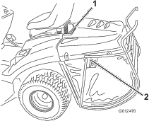
-
Lift up the collector using the top support bar (Figure 35).
Installing the Grass Collector
-
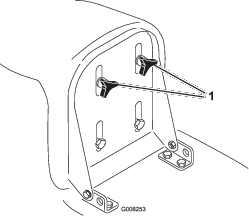
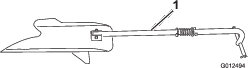
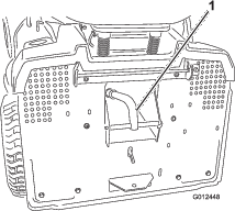
Hang the top support bar onto the 2 notches in the support bracket at the rear of the machine (Figure 36).
Note: Ensure that the grass collector is properly seated on the mower. The mower will not function unless the grass collector is properly attached.
-
Unlock the locking pin to allow for emptying the grass collector.
Cleaning the Grass Collector and Tunnel
-
Disengage the blades (PTO).
-
Set the parking brake.
-
Stop the engine and wait for all moving parts to stop.
-
Remove the ignition key.
-
Remove the grass collector; refer to Removing the Grass Collector.
-
Clean the collector bag with pressurized water.
-
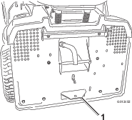
Wipe the area around the full-bag sensor.
-
Clean the inside of the discharge tunnel all the way to the mower.
-
Install the grass collector; refer to Installing the Grass Collector.
Note: Allow the bag to dry thoroughly before installing it.
Servicing the Blades
Note: Determine the left and right sides of the machine from the normal operating position.
To ensure a superior quality of cut, keep the blades sharp. For convenient sharpening and replacement, keep extra blades.
Danger
Worn or damaged blades can break and a piece of the blade could be thrown toward you or bystanders, resulting in serious personal injury or death.
-
Inspect the blades periodically for wear or damage.
-
Replace worn or damaged blades.
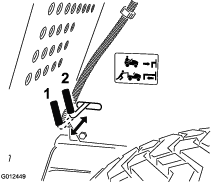
Inspecting the Blades
-
Remove the mower; refer to Removing the Mower.
-
Inspect the cutting edges (Figure 37). If the edges are not sharp or have nicks, remove the blades and sharpen them; refer to Sharpening the Blades.
-
Inspect the blades, especially the bent edges (Figure 37). If you notice any wear or damage in this area, immediately install new blades.
-
If the shear pins are broken, replace them immediately (Figure 37).
Important: If the shear pins are broken, the mower belt may be damaged. Inspect the belt; if the belt is damaged, contact an Authorized Service Dealer.
Close sectionRemoving the Blades
-
Remove the mower; refer to Removing the Mower.
-
Carefully tip the mower over.
-
Remove the bolts, washers, and blades (Figure 37). Wedge a block of wood between each blade and the mower to lock the blade when you are removing each bolt.
Note: The right blade has a left-hand threaded bolt.
-
Inspect all parts; replace any that are worn or damaged.
Sharpening the Blades
-
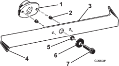
Use a file to sharpen the cutting edge at both ends of each blade (Figure 38). Maintain the original angle. The blade retains its balance if you remove the same amount of material from both cutting edges.

-
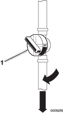
Check the balance of each blade by putting it on a blade balancer (Figure 39). If the blade stays in a horizontal position, the blade is balanced and can be used. If the blade is not balanced, file some metal off the back side of the blade. Repeat this step until each blade is balanced.

Installing the Blades
-
Install the blades, washers, and blade bolts (Figure 37).
Important: The bent edges of the blades must be pointing toward the top of the mower to ensure proper cutting.
-
Tighten the blade bolts to 37 ft-lb (50 N∙m).
Removing the Mower
-
Park the machine on a level surface.
-
Disengage the blades (PTO).
-
Set the parking brake.
-
Stop the engine and wait for all moving parts to stop.
-
Remove the ignition key.
-
Disconnect the wire from the spark plug.
-
Move the height-of-cut lever to the lowest position.
-
If the mulch plug is installed, remove it; refer to Mulching the Grass.
-
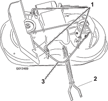
Remove the belt from the clutch pulley (Figure 40).
-
Remove the 2 bolts and nuts from the front linkage, and pull apart the front linkage to remove it from the machine.
-
Remove the pins from the 4 rear links and remove the links from the tractor (Figure 40).
Note: You can leave the links attached to the mower as shown in (Figure 40).
-
Lift up on the mower end of the discharge chute to free the mower from the notches in the discharge chute.
-
Pull the mower deck out from under the left side of the machine.
Installing the Mower
Reverse the procedure for Removing the Mower.
Close sectionAdjusting the Front-to-Rear Blade Slope
Check the front-to-rear blade slope whenever you install the mower.
-
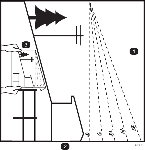
Measure the distance between the front tip of the left blade and the flat surface (Figure 41). Repeat for the rear tip of the left blade.
Note: The distance from the front tip of the left blade to the flat surface should be approximately 6 mm lower than the distance from the rear tip of the left blade and the flat surface. If so, go to Leveling the Mower from Side-to-Side. Otherwise, go to the next step.
-
To obtain the proper height distance between the front and rear tips of the left blade, adjust the length of the linking rod (located on the left side of the machine) (Figure 42).
Note: Shorten the linking rod to decrease the blade slope; extend the linking rod to increase the blade slope.
-
Ensure that the front-to-rear blade slope is correct, then check the side-to-side level of the mower; refer to Leveling the Mower from Side-to-Side.
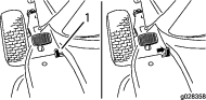
Leveling the Mower from Side-to-Side
The mower blades must be level from side to side. Check the side-to-side level whenever you install the mower or if you notice that your lawn has an uneven appearance.
-
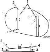
Carefully rotate the blades side to side (Figure 43).

-
Measure between the outside cutting edges and the flat surface (Figure 43). Ensure that the measurements are within 3 mm of each other. If they are not, go to the next step.
-
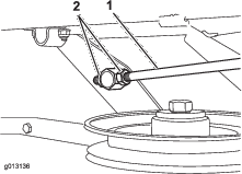
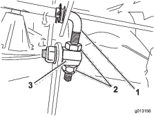
Loosen the nuts on the front and rear adjustable links (located on the right side of the mower) so that the links are free to move through the trunnions (Figure 44 and Figure 45).
-
Raise or lower the right side of the mower housing by turning the nuts until the distance from the outside edges of the blades to the flat surface (Figure 43) are within 3 mm of each other, and tighten the nuts on the front and rear adjustable links.
Checking and Setting the Cutting Height
Before you check the slope, inflate the front and rear tires to the recommended air pressure; refer to Checking the Tire Pressure. If the front of the mower is not within 4 to 11 mm lower than the rear of the mower, adjust the blade slope.
Check and adjust the cutting height of the blades whenever you install the mower.
-
Park the machine on a level surface.
-
Ensure that the air pressure in the tires are set to the recommended level; refer to Checking the Tire PressureChecking the Tire Pressure.
-
Disengage the blades (PTO) and set the parking brake.
-
Stop the engine, wait for all moving parts to stop, and remove the ignition key.
-
Disconnect the wire from the spark plug.
-
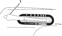
Move the height-of-cut lever to the middle (4) position.
Carefully rotate the blades front to rear (Figure 46).
-
Measure the distance between the front tip of the left blade and the flat surface (Figure 46).
Note: The distance should be 55 mm. If it is, go to step Adjusting the Front-to-Rear Blade Slope. Otherwise, go to the next step.
-
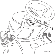
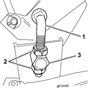
Loosen the jam nut on at the end of the turnbuckle (on the right side of the machine; refer to Figure 47), and adjust the turnbuckle until the distance between the front tip of the left blade and the flat surface is 55 mm.
Note: You may need to move the height-of-cut lever to the lowest (1) position before you adjust the turnbuckle. Return the cutting height setting to the middle (4) position before checking the distance between the front tip of the left blade and the flat surface.
Note: To raise the blade tip, turn the turnbuckle clockwise; to lower the blade tip, turn the turnbuckle counterclockwise.
-
Tighten the turnbuckle jam nut.
Installing the Adjustable Links
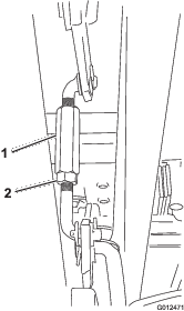
If you install a replacement adjustable link, you must approximately adjust the new adjustable link before setting the cutting height, adjusting the front-to-rear slope, and leveling the mower from side-to-side.
Install the front or rear adjustable link as shown in Figure 48.