Warning
CALIFORNIA
Proposition 65 Warning
This product contains a chemical or chemicals known to the State of California to cause cancer, birth defects, or reproductive harm.
Setup
Preparing the Machine
Note: Determine the left and right sides of the machine from the normal operating position.
-
Park the machine on a level surface.
-
Engage the parking brake.
-
Shut off the engine and remove the key.
-
Raise the cargo bed; refer to your machine Operator’s Manual.
-
Disconnect the battery; refer to your machine Operator’s Manual.
Installing the Wire Harness, Relay, and Timer Module
Parts needed for this procedure:
| Wire harness | 1 |
| Timer module | 1 |
| Relay | 1 |
| Screw | 2 |
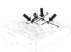
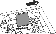
Use the following instructions and illustrations to route and connect the wire harness. Refer to Figure 1 for an overview of the wire-harness position.
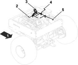
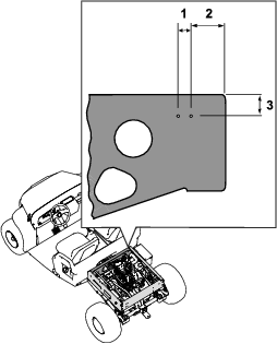
Installing the Timer Module and Relay
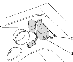
Installing the Wire Harness to the Solenoid and Engine
-
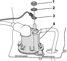
Remove the cover from start/run solenoid (Figure 4).
-
Use the solenoid nut and lock washer to secure the ring terminal to the solenoid (Figure 5).
-
Install the cover over the solenoid.
-
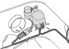
Connect the wire harness to the timer module and the relay (Figure 6).
-
Install the ring terminal to the engine magneto; refer to Figure 1 for the wire-harness position.
Completing the Installation
Parts needed for this procedure:
| Cable tie | 3 |
-
Connect the positive battery cable to the positive battery terminal; refer to your machine Operator’s Manual.
-
Connect the ring terminal of the wire harness to the negative battery terminal; refer to Figure 1 for the wire-harness position.
-
Connect the negative battery cable to the negative battery terminal; refer to your machine Operator’s Manual.
-
Use 3 cable ties to secure the kit wire harness to the existing wire harness; refer to Figure 7 for the position of the cable ties.